FACULTY OF ENGINEERINGSCIENCES AND TECHNOLOGY
Group Members:
NAME ID
Owais imam 14248
Areeba Fatima 15775
Maryam Riaz 15150
EMBE
DDED
SYSTE
M
LAB
MANU
AL
2.
FACULTY OF ENGINEERINGSCIENCES AND TECHNOLOGY
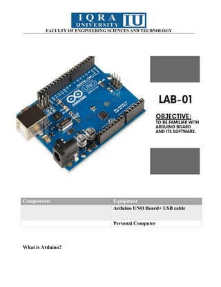
Components Equipment
Arduino UNO Board+ USB cable
Personal Computer
What is Arduino?
3.
FACULTY OF ENGINEERINGSCIENCES AND TECHNOLOGY
Arduino is an open-source electronics platform based on easy-to-use hardware and
software. It can read inputs (like a light sensor or button press) and turn them into
outputs (such as activating a motor or lighting an LED). You program it using the
Arduino programming language and the Arduino Software (IDE). Arduino is widely
used in projects ranging from simple DIY tasks to complex scientific instruments. A
global community of makers—students, hobbyists, artists, and professionals—has
developed around it, making Arduino an accessible tool for beginners and experts
alike.
Why Use Arduino?
Arduino stands out for its simplicity, affordability, and flexibility. It is used in
diverse fields like robotics, music, art, and education. The IDE runs on Windows,
Mac, and Linux, making it versatile for many users. Arduino is an ideal platform for
learning electronics and programming due to its:
Inexpensive cost: Affordable compared to other platforms.
Cross-platform compatibility: Works on multiple operating systems.
Simple programming environment: Easy for beginners, with advanced
features for experienced users.
Open-source software and hardware: Customizable and extensible.
Arduino UNO
The Arduino Uno is one of the most popular Arduino boards. It is based on the
ATmega328P microcontroller and has:
14 digital input/output pins (6 can be used for PWM outputs)
6 analog inputs
16 MHz quartz crystal
USB connection for power and programming
Power jack for external power
ICSP header and reset button
It can be powered through USB or an external supply (up to 20V). The Uno is a
powerful and flexible board for both beginners and advanced users
FACULTY OF ENGINEERINGSCIENCES AND TECHNOLOGY
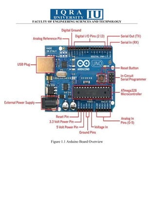
1. Microcontroller: The Arduino UNO is based on the ATmega328P
microcontroller, which serves as the brain of the board and executes the
uploaded code.
2. Digital Input/Output Pins: The Arduino UNO has a total of 14 digital
input/output pins that allow reading digital inputs from sensors or controlling
digital outputs to actuators like LEDs, motors, or relays.
3. Analog Input Pins: There are 6 analog input pins on the Arduino UNO for
reading analog inputs from sensors such as temperature sensors or
potentiometers.
4. PWM Pins: Some digital pins on the Arduino UNO can be utilized as PWM
(Pulse Width Modulation) pins, enabling control over the intensity of outputs
like LEDs or the speed of motors.
5. USB Interface: The USB interface on the Arduino UNO is responsible for
uploading code to the board, facilitating communication with a computer, and
powering the board.
6. Power Jack: To power the board, an external power source such as a battery
or wall adapter can be connected to the power jack on the Arduino UNO.
7. ICSP Header: The ICSP (In-Circuit Serial Programming) header on the
Arduino UNO is employed for programming the microcontroller using an
external programmer.
8. 16 MHz Quartz Crystal: The Arduino UNO uses a 16 MHz quartz crystal to
provide a clock signal to the microcontroller.
9. Reset Button: The reset button on the Arduino UNO allows for resetting the
board and restarting the program from the beginning.
6.
FACULTY OF ENGINEERINGSCIENCES AND TECHNOLOGY
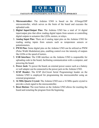
Arduino IDE:
Figure 1.2: Arduino
It is the Arduino IDE that you use to write code for Arduino and Arduino
compatible boards. Before running our first sketch, let’s get familiar with the
development environment ‘Arduino IDE’.
Arduino IDE is a development environment which is a program where you write
code, upload it to the board and check for errors. If you open the Arduino IDE in
Windows OS it will look familiar to this.
Figure 1.3: Arduino IDE in Windows OS
7.
FACULTY OF ENGINEERINGSCIENCES AND TECHNOLOGY
As you can see here, when you open the IDE it already contains two blank
functions which are the default functions, about these we will learn in the next part.
The Arduino IDE looks simple, let’s get a brief overview of it.
The IDE is split into the following four parts:
1. File menu at the top
2. Toolbar below this,
3. Code window
4. Message window
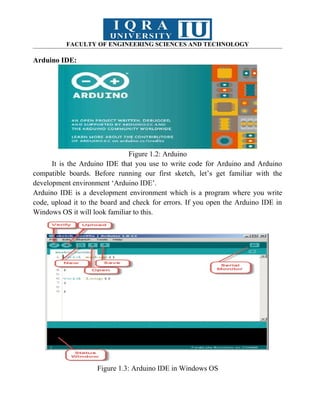
The buttons at toolbar provide easy access to most commonly used functions like
Verify, New, Upload, Open, Save, Serial Monitor.
Verify: This is used to check that your code is correct before uploading it to
the board.
Upload: Used to upload the code to your board.
New: This button creates a completely new sketch with two default functions
in another window. It is named with the current date by default which you
have to save before uploading.
Open: Opens a sketch.
Save: Save the current sketch.
Serial Monitor: This is a very useful tool for debugging the code. It opens
another window that displays the serial data being sent out by the board.
Figure 1.4: Serial Monitor
8.
FACULTY OF ENGINEERINGSCIENCES AND TECHNOLOGY
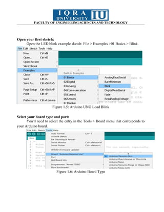
Open your first sketch:
Open the LED blink example sketch: File > Examples >01.Basics > Blink.
Figure 1.5: Arduino UNO Load Blink
Select your board type and port:
You'll need to select the entry in the Tools > Board menu that corresponds to
your Arduino board.
Figure 1.6: Arduino Board Type
9.
FACULTY OF ENGINEERINGSCIENCES AND TECHNOLOGY
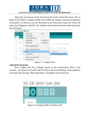
Select the serial device of the board from the Tools | Serial Port menu. This is
likely to be COM3 or higher (COM1 and COM2 are usually reserved for hardware
serial ports). To find out, you can disconnect your board and re-open the menu; the
entry that disappears should be the Arduino board. Reconnect the board and select
that serial port.
Figure 1.7: Arduino Port
Upload the program:
Now, simply click the "Upload" button in the environment. Wait a few
seconds - you should see the RX and TX leds on the board flashing. If the upload is
successful, the message "Done uploading." will appear in the status bar.
Figure 1.8: Arduino IDE in Windows OS
10.
FACULTY OF ENGINEERINGSCIENCES AND TECHNOLOGY
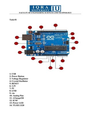
Task-01
1: USB
2: Power Button
3: Voltage Regulator
4: Crystal Oscillator
5: RESET
6: 3.3V
7: 5V
8: GND
9: vin
10: Analog Pins
11: ATmega328
12: ICSP
13: Power LED
14: TX RX LED
11.
FACULTY OF ENGINEERINGSCIENCES AND TECHNOLOGY
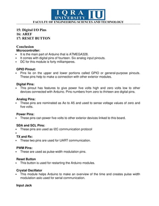
15: Digital I/O Pins
16: AREF
17: RESET BUTTON
Conclusion
Microcontroller:
It is the main part of Arduino that is ATMEGA328.
It comes with digital pins of fourteen. Six analog input pinouts.
DC for this module is forty milliamperes.
GPIO Pinout:
Pins lie on the upper and lower portions called GPIO or general-purpose pinouts.
These pins help to make a connection with other exterior modules.
Digital Pins:
This pinout has features to give power five volts high and zero volts low to other
devices connected with Arduino. Pins numbers from zero to thirteen are digital pins.
Analog Pins:
These pins are nominated as Ao to A5 and used to sense voltage values of zero and
five volts.
Power Pins:
These pins can power five volts to other exterior devices linked to this board.
SDA and SCL Pins:
These pins are used as I2C communication protocol
TX and Rx:
These two pins are used for UART communication.
PWM Pins:
These are used as pulse-width modulation pins.
Reset Button
This button is used for restarting the Arduino modules.
Crystal Oscillator
This module helps Arduino to make an overview of the time and creates pulse width
modulation aslo used for serial communication.
Input Jack
12.
FACULTY OF ENGINEERINGSCIENCES AND TECHNOLOGY
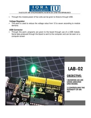
Through this module power of five volts can be given to Arduino through USB.
Voltage Regulator
This point is used to reduce the voltage value from 12 to seven according to module
demand.
USB Connector
Through this point, programs are given to the board through use of a USB module.
Serial data produced through the board is sent to the computer and can be seen on a
computer screen
13.
FACULTY OF ENGINEERINGSCIENCES AND TECHNOLOGY
Components Equipment
LED Arduino UNO Board+ USB cable
Jumper Wires Personal Computer
Potentiometer
14.
FACULTY OF ENGINEERINGSCIENCES AND TECHNOLOGY
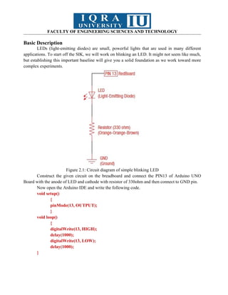
Basic Description
LEDs (light-emitting diodes) are small, powerful lights that are used in many different
applications. To start off the SIK, we will work on blinking an LED. It might not seem like much,
but establishing this important baseline will give you a solid foundation as we work toward more
complex experiments.
Figure 2.1: Circuit diagram of simple blinking LED
Construct the given circuit on the breadboard and connect the PIN13 of Arduino UNO
Board with the anode of LED and cathode with resistor of 330ohm and then connect to GND pin.
Now open the Arduino IDE and write the following code.
void setup()
{
pinMode(13, OUTPUT);
}
void loop()
{
digitalWrite(13, HIGH);
delay(1000);
digitalWrite(13, LOW);
delay(1000);
}
15.
FACULTY OF ENGINEERINGSCIENCES AND TECHNOLOGY
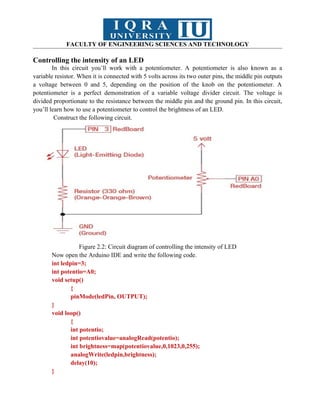
Controlling the intensity of an LED
In this circuit you’ll work with a potentiometer. A potentiometer is also known as a
variable resistor. When it is connected with 5 volts across its two outer pins, the middle pin outputs
a voltage between 0 and 5, depending on the position of the knob on the potentiometer. A
potentiometer is a perfect demonstration of a variable voltage divider circuit. The voltage is
divided proportionate to the resistance between the middle pin and the ground pin. In this circuit,
you’ll learn how to use a potentiometer to control the brightness of an LED.
Construct the following circuit.
Figure 2.2: Circuit diagram of controlling the intensity of LED
Now open the Arduino IDE and write the following code.
int ledpin=3;
int potentio=A0;
void setup()
{
pinMode(ledPin, OUTPUT);
}
void loop()
{
int potentio;
int potentiovalue=analogRead(potentio);
int brightness=map(potentiovalue,0,1023,0,255);
analogWrite(ledpin,brightness);
delay(10);
}
16.
FACULTY OF ENGINEERINGSCIENCES AND TECHNOLOGY
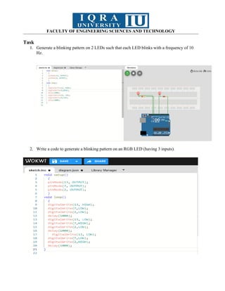
Task
1. Generate a blinking pattern on 2 LEDs such that each LED blinks with a frequency of 10
Hz.
2. Write a code to generate a blinking pattern on an RGB LED (having 3 inputs).
17.
FACULTY OF ENGINEERINGSCIENCES AND TECHNOLOGY
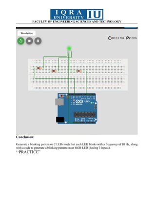
Conclusion:
Generate a blinking pattern on 2 LEDs such that each LED blinks with a frequency of 10 Hz, along
with a code to generate a blinking pattern on an RGB LED (having 3 inputs).
‘‘PRACTICE”
FACULTY OF ENGINEERINGSCIENCES AND TECHNOLOGY
Components Equipment
LED
Jumper Wires
Arduino UNO Board+ USB cable
Push Button Personal Computer
Basic Description
Starting with some basic concepts and gradually introducing the pull-up resistor:
20.
FACULTY OF ENGINEERINGSCIENCES AND TECHNOLOGY
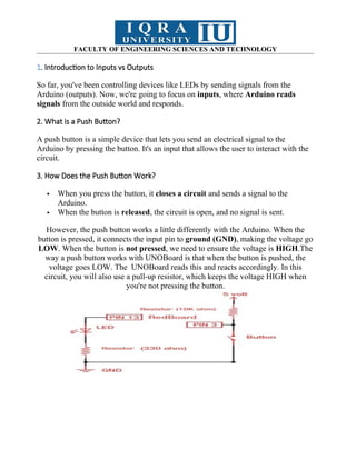
1. Introduction to Inputs vs Outputs
So far, you've been controlling devices like LEDs by sending signals from the
Arduino (outputs). Now, we're going to focus on inputs, where Arduino reads
signals from the outside world and responds.
2. What is a Push Button?
A push button is a simple device that lets you send an electrical signal to the
Arduino by pressing the button. It's an input that allows the user to interact with the
circuit.
3. How Does the Push Button Work?
When you press the button, it closes a circuit and sends a signal to the
Arduino.
When the button is released, the circuit is open, and no signal is sent.
However, the push button works a little differently with the Arduino. When the
button is pressed, it connects the input pin to ground (GND), making the voltage go
LOW. When the button is not pressed, we need to ensure the voltage is HIGH.The
way a push button works with UNOBoard is that when the button is pushed, the
voltage goes LOW. The UNOBoard reads this and reacts accordingly. In this
circuit, you will also use a pull-up resistor, which keeps the voltage HIGH when
you're not pressing the button.
21.
FACULTY OF ENGINEERINGSCIENCES AND TECHNOLOGY
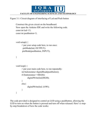
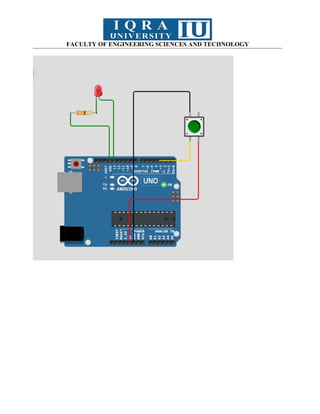
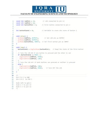
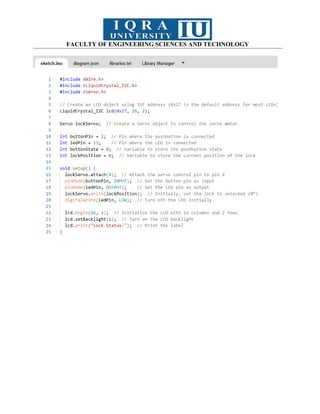
Figure 3.1: Circuit diagram of interfacing of Led and Push button
Construct the given circuit on the breadboard.
Now open the Arduino IDE and write the following code.
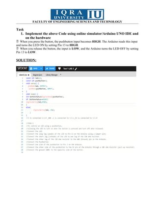
const int led=13;
const int pushbutton=3;
void setup() {
// put your setup code here, to run once:
pinMode(led, OUTPUT);
pinMode(pushbutton, INPUT);
}
void loop() {
// put your main code here, to run repeatedly:
int buttonstatus=digitalRead(pushbutton);
if (buttonstatus==HIGH){
digitalWrite(led,HIGH);
}
else{
digitalWrite(led, LOW);
}
}
The code provided is designed to control an LED using a pushbutton, allowing the
LED to turn on when the button is pressed and turn off when released. Here’s a step-
by-step breakdown of how the code works:
22.
FACULTY OF ENGINEERINGSCIENCES AND TECHNOLOGY
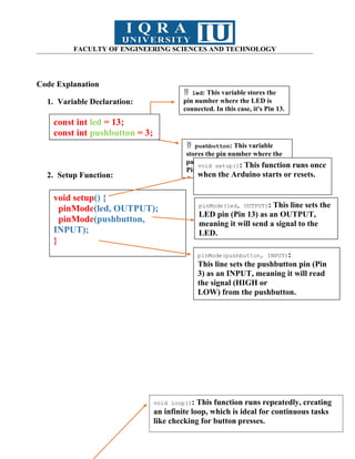
Code Explanation
1. Variable Declaration:
2. Setup Function:
const int led = 13;
const int pushbutton = 3;
led: This variable stores the
pin number where the LED is
connected. In this case, it's Pin 13.
pushbutton: This variable
stores the pin number where the
pushbutton is connected, which is
Pin 3.
const int led = 13;
const int pushbutton = 3;
void setup() {
pinMode(led, OUTPUT);
pinMode(pushbutton,
INPUT);
}
void setup(): This function runs once
when the Arduino starts or resets.
pinMode(led, OUTPUT): This line sets the
LED pin (Pin 13) as an OUTPUT,
meaning it will send a signal to the
LED.
pinMode(pushbutton, INPUT):
This line sets the pushbutton pin (Pin
3) as an INPUT, meaning it will read
the signal (HIGH or
LOW) from the pushbutton.
void loop(): This function runs repeatedly, creating
an infinite loop, which is ideal for continuous tasks
like checking for button presses.
23.
FACULTY OF ENGINEERINGSCIENCES AND TECHNOLOGY
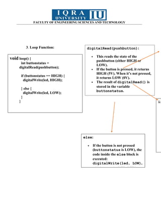
3. Loop Function:
void loop() {
int buttonstatus =
digitalRead(pushbutton);
if (buttonstatus == HIGH) {
digitalWrite(led, HIGH);
} else {
digitalWrite(led, LOW);
}
}
digitalRead(pushbutton):
This reads the state of the
pushbutton (either HIGH or
LOW).
If the button is pressed, it returns
HIGH (5V). When it’s not pressed,
it returns LOW (0V).
The result of digitalRead() is
stored in the variable
buttonstatus.
if
else:
If the button is not pressed
(buttonstatus is LOW), the
code inside the else block is
executed:
digitalWrite(led, LOW),
which turns the LED OFF by
24.
FACULTY OF ENGINEERINGSCIENCES AND TECHNOLOGY
Task
1. Implement the above Code using online simulator/Arduino UNO IDE and
on the hardware
When you press the button, the pushbutton input becomes
HIGH. The Arduino reads this input
and turns the LED ON by setting Pin 13 to HIGH.
When you release the button, the input is
LOW, and the Arduino turns the LED OFF by setting
Pin 13 to LOW.
SOLUTION:
FACULTY OF ENGINEERINGSCIENCES AND TECHNOLOGY
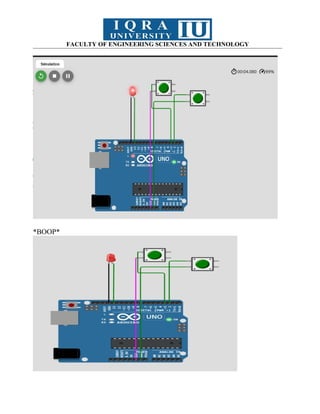
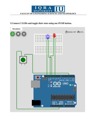
2. Write an Arduino sketch to control an LED using two push buttons.
The LED should turn on if one of the buttons is pressed, but not both, and turn
off if both buttons are pressed or neither.
SOLUTION:
FACULTY OF ENGINEERINGSCIENCES AND TECHNOLOGY
LINKS:
TASK 1= https://wokwi.com/projects/413065494078711809
TASK 2= https://wokwi.com/projects/413067509202272257
TASK 3= https://wokwi.com/projects/418431058721863681
Conclusion:
With this we have are well informed on the input and output & pushbutton along
with their working.
31.
FACULTY OF ENGINEERINGSCIENCES AND TECHNOLOGY
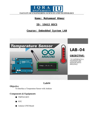
Name: Muhammad Ahmer
ID: 15612 BSCS
Course: Embedded System LAB
Lab#4
Objective
To Interface a Temperature Sensor with Arduino
Components & Equipments
● TMP36/LM35
● NTC
● Arduino UNO Board
32.
FACULTY OF ENGINEERINGSCIENCES AND TECHNOLOGY
● Jumper Wires
● Personal Computer
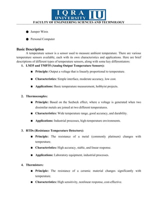
Basic Description
A temperature sensor is a sensor used to measure ambient temperature. There are various
temperature sensors available, each with its own characteristics and applications. Here are brief
descriptions of different types of temperature sensors, along with some key differentiators:
1. LM35 and TMP35 (Analog Output Temperature Sensors):
▪ Principle: Output a voltage that is linearly proportional to temperature.
▪ Characteristics: Simple interface, moderate accuracy, low cost.
▪ Applications: Basic temperature measurement, hobbyist projects.
2. Thermocouples:
▪ Principle: Based on the Seebeck effect, where a voltage is generated when two
dissimilar metals are joined at two different temperatures.
▪ Characteristics: Wide temperature range, good accuracy, and durability.
▪ Applications: Industrial processes, high-temperature environments.
3. RTDs (Resistance Temperature Detectors):
▪ Principle: The resistance of a metal (commonly platinum) changes with
temperature.
▪ Characteristics: High accuracy, stable, and linear response.
▪ Applications: Laboratory equipment, industrial processes.
4. Thermistors:
▪ Principle: The resistance of a ceramic material changes significantly with
temperature.
▪ Characteristics: High sensitivity, nonlinear response, cost-effective.
33.
FACULTY OF ENGINEERINGSCIENCES AND TECHNOLOGY
▪ Applications: Temperature control systems, automotive applications.
5. Infrared (IR) Sensors:
▪ Principle: Detects the infrared radiation emitted by an object to determine its
temperature.
▪ Characteristics: Non-contact, suitable for measuring surface temperatures.
▪ Applications: Medical thermometers, industrial monitoring.
6. DS18B20 (Digital Temperature Sensor):
▪ Principle: Measures temperature digitally using the OneWire protocol.
▪ Characteristics: Digital output, high accuracy, easy to interface.
▪ Applications: Environmental monitoring, consumer electronics.
7. Bimetallic Temperature Sensors:
▪ Principle: Two different metals with different coefficients of thermal expansion are
bonded together.
▪ Characteristics: Simple design, cost-effective.
▪ Applications: Thermostats, temperature switches.
8. Gas Thermometers:
▪ Principle: Based on the expansion or contraction of gas with temperature changes.
▪ Characteristics: High precision, suitable for laboratory use.
▪ Applications: Calibration standards, scientific research.
When choosing a temperature sensor for a specific application, factors such as the required
accuracy, temperature range, response time, and cost should be considered. Different sensors are
suitable for different scenarios, and the choice depends on the specific needs of the project or
system.
34.
FACULTY OF ENGINEERINGSCIENCES AND TECHNOLOGY
Selection of Sensor:
Selecting the right temperature sensor for your application involves considering several
factors. Here are key considerations to help you make an informed decision:
1) Temperature Range:
Choose a sensor that covers the temperature range relevant to your application.
Some sensors are better suited for low temperatures, while others are designed for high-
temperature environments.
2) Accuracy:
Different applications have different accuracy requirements. Ensure that the sensor's
accuracy meets the needs of your project. For precise temperature measurements, sensors
like RTDs or thermocouples might be more appropriate.
3) Response Time:
Consider the response time required for your application. Some sensors provide
faster real-time measurements, while others may have a slower response. For dynamic
systems, a faster response time may be critical.
4) Environment and Conditions:
Assess the environmental conditions where the sensor will be used. Consider
factors such as humidity, vibration, and the presence of corrosive or harsh substances.
Some sensors are better suited for specific environmental conditions.
5) Cost:
Evaluate the cost of the sensor, including the sensor itself and any additional
components needed for interfacing. While thermocouples and thermistors are often cost-
effective, more specialized sensors like RTDs or infrared sensors may be pricier.
6) Mounting and Packaging:
Consider the physical size and packaging of the sensor. Ensure it can be easily
integrated into your system and is suitable for the available space.
7) Power Consumption:
Evaluate the power requirements of the sensor. Low-power sensors might be crucial
for battery-powered devices or applications where power consumption is a critical factor.
8) Linearity and Calibration:
35.
FACULTY OF ENGINEERINGSCIENCES AND TECHNOLOGY
Some sensors have linear responses, while others may exhibit non-linear behavior.
Understand the linearity of the sensor's output and whether calibration is necessary for your
application.
9) Interfacing and Compatibility:
Check the interface of the sensor and ensure it is compatible with your
microcontroller or data acquisition system. Some sensors provide analog outputs, while
others offer digital interfaces.
10) Reliability and Longevity:
Assess the reliability and lifespan of the sensor. Some sensors may degrade over
time or with extended use, so choose a sensor that meets your longevity requirements.
11) Ease of Installation:
Consider how easy it is to install and calibrate the sensor. Some sensors require
careful calibration, while others are more plug-and-play.
Always refer to the datasheets and technical specifications of the sensors you are
considering, and if possible, conduct tests or simulations to ensure the sensor meets your
specific requirements.
Compare The LM35 and TMP35 sensors
The LM35 and TMP35 are similar temperature sensors, but they are not exactly the same.
Both sensors are analog-output temperature sensors that provide a voltage output proportional to
the temperature in Celsius.
Here are the key differences:
a) Voltage Range:
● LM35: The LM35 outputs 10 mV per degree Celsius and has a voltage range
typically between 0 and 1.5V.
● TMP35: The TMP35 also outputs 10 mV per degree Celsius but has a voltage range
typically between 500 mV and 1500 mV.
b) Supply Voltage:
● LM35: The LM35 typically operates with a supply voltage between 4V and 30V.
● TMP35: The TMP35 typically operates with a supply voltage between 2.7V and
5.5V.
36.
FACULTY OF ENGINEERINGSCIENCES AND TECHNOLOGY
c) Temperature Range:
● LM35: The LM35 has a temperature range from -55°C to 150°C.
● TMP35: The TMP35 has a temperature range from -40°C to 125°C.
In terms of usage, they are often interchangeable in many applications, especially when
dealing with a narrow temperature range. However, it's essential to consider the differences in their
electrical characteristics and voltage ranges, especially if you have specific requirements for your
project.
TMP36
This particular sensor has three pins – a positive, a ground, and a signal. This is a linear
temperature sensor. A change in temperature of one degree centigrade is equal to a change of 10
millivolts at the sensor output. The TMP36 sensor has a nominal 750 mV at 25°C (about room
temperature). In this circuit, you’ll learn how to integrate the temperature sensor with your
RedBoard, and use the Arduino IDE’s serial monitor to display the temperature.
Figure 4.1: Circuit diagram of interfacing of TMP36 sensor with Arduino
Construct the given circuit on the breadboard.
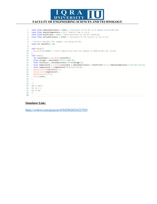
Now open the Arduino IDE and write the following code.
const int temperaturePin = A0;
37.
FACULTY OF ENGINEERINGSCIENCES AND TECHNOLOGY
void setup()
{
Serial.begin(9600);
}
void loop()
{
float voltage, degreesC, degreesF;
voltage = getVoltage(temperaturePin);
degreesC = (voltage - 0.5) * 100.0;
degreesF = degreesC * (9.0/5.0) + 32.0;
Serial.print("Voltage: ");
Serial.print(voltage);
Serial.print("Temperature in Centigrade:");
Serial.println(degreesC);
Serial.print("Temperature in Fahrenheit:");
Serial.println(degreesF);
delay(1000);
}
float getVoltage(int pin)
{
return (analogRead(pin) * 0.004882814);
}
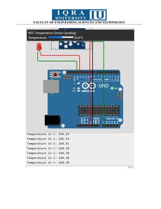
NTC (Negative Temperature Coefficient)
An NTC (Negative Temperature Coefficient) thermistor is a type of analog temperature
sensor. NTC thermistors are resistors whose resistance decreases with an increase in temperature.
They are commonly used for temperature measurement and temperature compensation in various
electronic devices.
Here's a basic guide on how to use an NTC thermistor as an analog temperature sensor with
an Arduino:
38.
FACULTY OF ENGINEERINGSCIENCES AND TECHNOLOGY
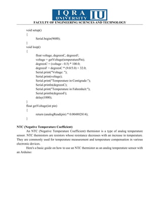
Figure 4.2: Circuit diagram of interfacing of NTC sensor with Arduino
Construct the given circuit on the breadboard.
Now open the Arduino IDE and write the following code.
// Define the pin to which the NTC thermistor is connected
const int ntcPin = A0;
void setup() {
// Start serial communication
Serial.begin(9600);
}
void loop() {
// Read the analog value from the NTC thermistor
int analogValue = analogRead(ntcPin);
// Convert the analog value to resistance using a known resistor in series with the
thermistor
float resistance = 10000.0 / ((1023.0 / analogValue) - 1.0);
// Use the Steinhart-Hart equation to convert resistance to temperature in Celsius
float temperatureC = (1.0 / ((log(resistance / 10000.0) / 3950.0) + (1.0 / 298.15))) -
273.15;
39.
FACULTY OF ENGINEERINGSCIENCES AND TECHNOLOGY
// Print the temperature to the serial monitor
Serial.print("Temperature: ");
Serial.print(temperatureC);
Serial.println(" °C");
// Wait for a second before taking the next reading
delay(1000);
}
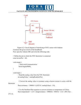
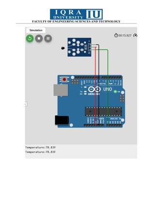
Task
1. Display the temperature in Centigrade after every 5 seconds.
40.
FACULTY OF ENGINEERINGSCIENCES AND TECHNOLOGY
Simulator Link:
https://wokwi.com/projects/418429026300341249
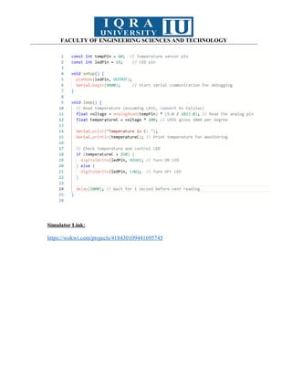
2. Display the temperature in Fahrenheit after every 15 seconds.
FACULTY OF ENGINEERINGSCIENCES AND TECHNOLOGY
Simulator Link:
https://wokwi.com/projects/418430109441695745
46.
FACULTY OF ENGINEERINGSCIENCES AND TECHNOLOGY
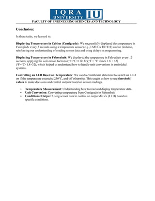
Conclusion:
In these tasks, we learned to:
Displaying Temperature in Celsius (Centigrade): We successfully displayed the temperature in
Centigrade every 5 seconds using a temperature sensor (e.g., LM35 or DHT11) and an Arduino,
reinforcing our understanding of reading sensor data and using delays in programming.
Displaying Temperature in Fahrenheit: We displayed the temperature in Fahrenheit every 15
seconds, applying the conversion formula (°F=°C×1.8+32)(°F = °C times 1.8 + 32)
(°F=°C×1.8+32), which helped us understand how to handle unit conversions in embedded
systems.
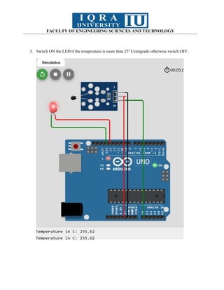
Controlling an LED Based on Temperature: We used a conditional statement to switch an LED
on if the temperature exceeded 250°C, and off otherwise. This taught us how to use threshold
values to make decisions and control outputs based on sensor readings.
Temperature Measurement: Understanding how to read and display temperature data.
Unit Conversion: Converting temperature from Centigrade to Fahrenheit.
Conditional Output: Using sensor data to control an output device (LED) based on
specific conditions.
47.
FACULTY OF ENGINEERINGSCIENCES AND TECHNOLOGY
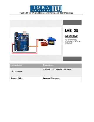
Components Equipment
Servo motor
Arduino UNO Board+ USB cable
Jumper Wires Personal Computer
48.
FACULTY OF ENGINEERINGSCIENCES AND TECHNOLOGY
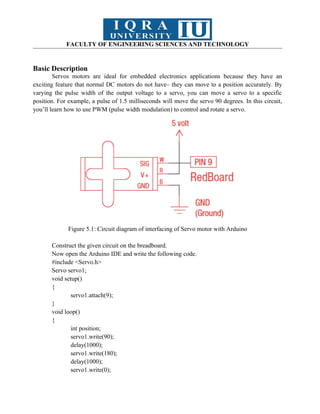
Basic Description
Servos motors are ideal for embedded electronics applications because they have an
exciting feature that normal DC motors do not have– they can move to a position accurately. By
varying the pulse width of the output voltage to a servo, you can move a servo to a specific
position. For example, a pulse of 1.5 milliseconds will move the servo 90 degrees. In this circuit,
you’ll learn how to use PWM (pulse width modulation) to control and rotate a servo.
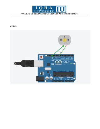
Figure 5.1: Circuit diagram of interfacing of Servo motor with Arduino
Construct the given circuit on the breadboard.
Now open the Arduino IDE and write the following code.
#include <Servo.h>
Servo servo1;
void setup()
{
servo1.attach(9);
}
void loop()
{
int position;
servo1.write(90);
delay(1000);
servo1.write(180);
delay(1000);
servo1.write(0);
49.
FACULTY OF ENGINEERINGSCIENCES AND TECHNOLOGY
delay(1000);
for(position = 0; position < 180; position += 2)
{
servo1.write(position);
delay(20);
}
for(position = 180; position >= 0; position -= 1)
{
servo1.write(position);
delay(20);
}
}
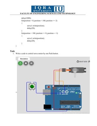
Task
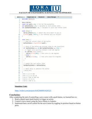
1. Write a code to control servo motor by one Push button.
50.
FACULTY OF ENGINEERINGSCIENCES AND TECHNOLOGY
Simulator Link:
https://wokwi.com/projects/414236609914245121
Conclusion:
After completing the task of controlling a servo motor with a push button, we learned how to:
1. Read a digital input (push button) to trigger an action.
2. Control a servo motor using the Servo library in Arduino.
3. Implement basic on/off control for the servo motor by toggling its position based on button
press.
51.
FACULTY OF ENGINEERINGSCIENCES AND TECHNOLOGY
Components Equipment
1. Servo Motor.
2. Pushbutton.
Arduino UNO Board+ USB cable
3. Status LED.
4. 16x2 I2C LCD.
5. 220-ohm resistor for LED.
Personal Computer
52.
FACULTY OF ENGINEERINGSCIENCES AND TECHNOLOGY
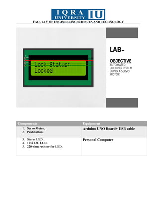
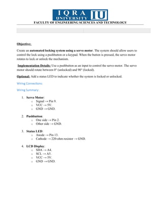
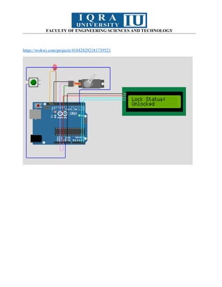
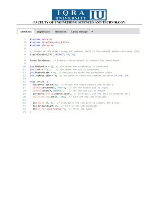
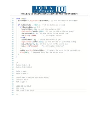
Objective:
Create an automated locking system using a servo motor. The system should allow users to
control the lock using a pushbutton or a keypad. When the button is pressed, the servo motor
rotates to lock or unlock the mechanism.
Implementation Details: Use a pushbutton as an input to control the servo motor. The servo
motor should rotate between 0° (unlocked) and 90° (locked).
Optional: Add a status LED to indicate whether the system is locked or unlocked.
Wiring Connections:
Wiring Summary:
1. Servo Motor:
o Signal → Pin 9.
o VCC → 5V.
o GND → GND.
2. Pushbutton:
o One side → Pin 2.
o Other side → GND.
3. Status LED:
o Anode → Pin 13.
o Cathode → 220-ohm resistor → GND.
4. LCD Display:
o SDA → A4.
o SCL → A5.
o VCC → 5V.
o GND → GND.
53.
FACULTY OF ENGINEERINGSCIENCES AND TECHNOLOGY
https://wokwi.com/projects/418428292181739521
FACULTY OF ENGINEERINGSCIENCES AND TECHNOLOGY
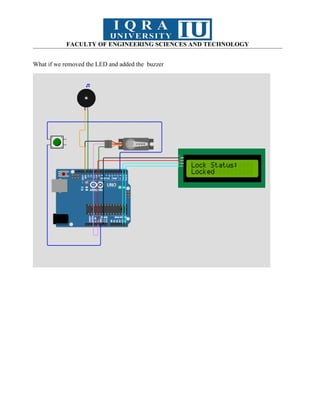
Conclusion
Add buzzer on the place of led … and is working on Locked and Unlocked:
59.
FACULTY OF ENGINEERINGSCIENCES AND TECHNOLOGY
Components Equipment
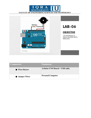
● Piezo Buzzer
Arduino UNO Board + USB cable
● Jumper Wires
Personal Computer
60.
FACULTY OF ENGINEERINGSCIENCES AND TECHNOLOGY
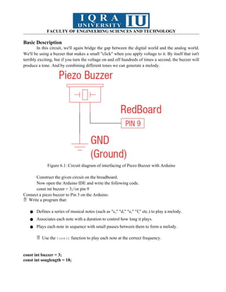
Basic Description
In this circuit, we'll again bridge the gap between the digital world and the analog world.
We'll be using a buzzer that makes a small "click" when you apply voltage to it. By itself that isn't
terribly exciting, but if you turn the voltage on and off hundreds of times a second, the buzzer will
produce a tone. And by combining different tones we can generate a melody.
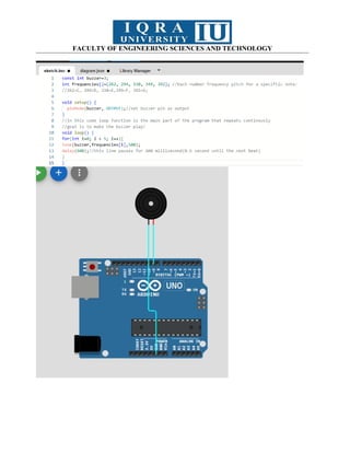
Figure 6.1: Circuit diagram of interfacing of Piezo Buzzer with Arduino
Construct the given circuit on the breadboard.
Now open the Arduino IDE and write the following code.
const int buzzer = 3;//or pin 9
Connect a piezo buzzer to Pin 3 on the Arduino.
Write a program that:
● Defines a series of musical notes (such as "c," "d," "e," "f," etc.) to play a melody.
● Associates each note with a duration to control how long it plays.
● Plays each note in sequence with small pauses between them to form a melody.
Use the
tone() function to play each note at the correct frequency.
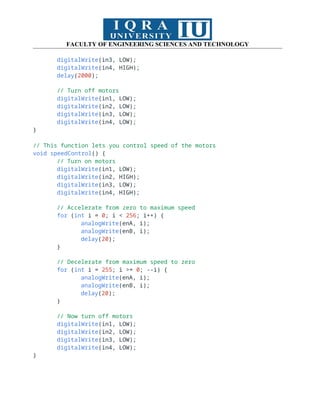
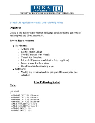
const int buzzer = 3;
const int songlength = 18;
61.
FACULTY OF ENGINEERINGSCIENCES AND TECHNOLOGY
char notes[] = "cdfda ag cdfdg gf";
int beats[] = {1, 1, 1, 1, 1, 1, 4, 4, 2, 1, 1, 1, 1, 1, 1, 1, 4, 4};
int tempo = 150;
void setup()
{
pinMode(buzzer, OUTPUT);
}
void loop()
{
int i, duration;
for (i = 0; i < songlength; i++) {
duration = beats[i] * tempo;
if (notes[i] == ' ') {
delay(duration);
} else {
tone(buzzer, frequency(notes[i]), duration);
delay(duration);
}
delay(tempo / 10);
}
}
int frequency(char note) {
int i;
const int numNotes = 8;
char names[] = {'c', 'd', 'e', 'f', 'g', 'a', 'b', 'C'};
int frequencies[] = {262, 294, 330, 349, 392, 440, 494, 523};
for (i = 0; i < numNotes; i++) {
if (names[i] == note) {
return frequencies[i]; // Yes! Return the frequency
}
}
return 0;
}
FACULTY OF ENGINEERINGSCIENCES AND TECHNOLOGY
Task:
1.Play a Simple Scale with a Buzzer
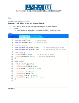
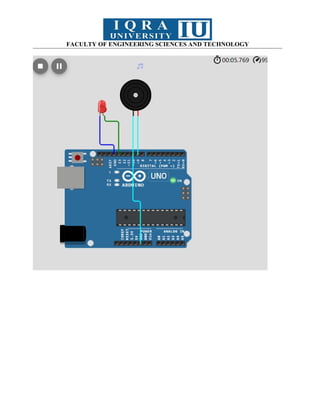
Question: . LED Blinks in Rhythm with the Buzzer
● Make the LED blink in sync with a buzzer's beeps at different intervals.
● Example:
○ LED and buzzer are on for 1 second and off for 0.5 seconds in a loop.
CODE:
OUTPUT:
FACULTY OF ENGINEERINGSCIENCES AND TECHNOLOGY
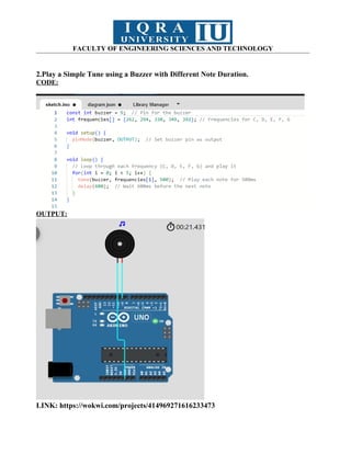
2.Play a Simple Tune using a Buzzer with Different Note Duration.
CODE:
OUTPUT:
LINK: https://wokwi.com/projects/414969271616233473
66.
FACULTY OF ENGINEERINGSCIENCES AND TECHNOLOGY
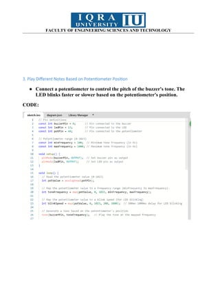
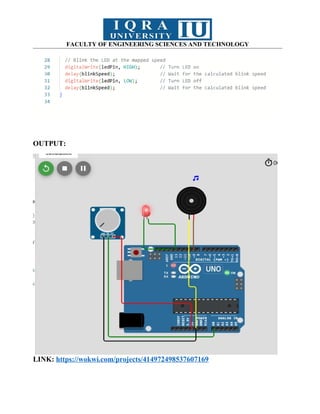
3. Play Different Notes Based on Potentiometer Position
● Connect a potentiometer to control the pitch of the buzzer's tone. The
LED blinks faster or slower based on the potentiometer's position.
CODE:
67.
FACULTY OF ENGINEERINGSCIENCES AND TECHNOLOGY
OUTPUT:
LINK: https://wokwi.com/projects/414972498537607169
68.
FACULTY OF ENGINEERINGSCIENCES AND TECHNOLOGY
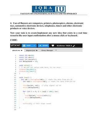
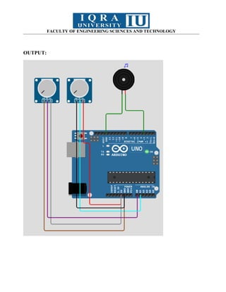
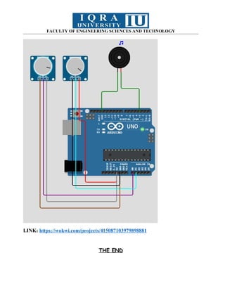
4. Uses of Buzzers are computers, printers, photocopiers, alarms, electronic
toys, automotive electronic devices, telephones, timers and other electronic
products or voice devices.
Now your task is to create/implement any new idea that exists in a real time
scenario like user input confirmation after a mouse click or keyboard.
CODE:
FACULTY OF ENGINEERINGSCIENCES AND TECHNOLOGY
LINK: https://wokwi.com/projects/415087103979898881
THE END
71.
FACULTY OF ENGINEERINGSCIENCES AND TECHNOLOGY
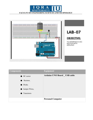
Components Equipment
● DC motor
● Resistor,
● Diode,
● Jumper Wires,
● Transistors
Arduino UNO Board _ USB cable
Personal Computer
72.
FACULTY OF ENGINEERINGSCIENCES AND TECHNOLOGY
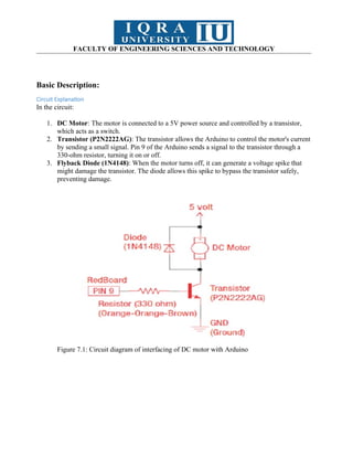
Basic Description:
Circuit Explanation
In the circuit:
1. DC Motor: The motor is connected to a 5V power source and controlled by a transistor,
which acts as a switch.
2. Transistor (P2N2222AG): The transistor allows the Arduino to control the motor's current
by sending a small signal. Pin 9 of the Arduino sends a signal to the transistor through a
330-ohm resistor, turning it on or off.
3. Flyback Diode (1N4148): When the motor turns off, it can generate a voltage spike that
might damage the transistor. The diode allows this spike to bypass the transistor safely,
preventing damage.
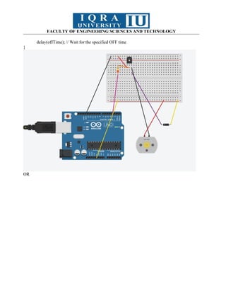
Figure 7.1: Circuit diagram of interfacing of DC motor with Arduino
73.
FACULTY OF ENGINEERINGSCIENCES AND TECHNOLOGY
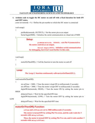
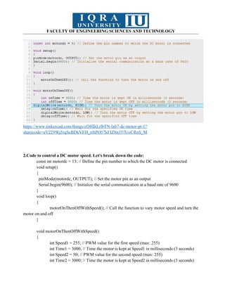
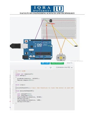
1. Arduino code to toggle the DC motor on and off with a fixed duration for both ON
and OFF states.
const int motordc = 9; // Define the pin number to which the DC motor is connected
void setup()
{
pinMode(motordc, OUTPUT); // Set the motor pin as an output
Serial.begin(9600); // Initialize the serial communication at a baud rate of 9600
}
void loop()
{
motorOnThenOff(); // Call the function to turn the motor on and off
}
void motorOnThenOff()
{
int onTime = 3000; // Time the motor is kept ON in milliseconds (3 seconds)
int offTime = 3000; // Time the motor is kept OFF in milliseconds (3 seconds)
digitalWrite(motordc, HIGH); // Turn the motor ON by setting the motor pin to
HIGH
delay(onTime); // Wait for the specified ON time
digitalWrite(motordc, LOW); // Turn the motor OFF by setting the motor pin to
LOW
delay(offTime); // Wait for the specified OFF time
}
Setup:
pinMode(motordc, OUTPUT); sets Pin 9 (connected to
the motor control) as an output.
Serial.begin(9600); initializes serial communication
for debugging, but it isn't used further in this code.
Loop:
The loop() function continuously calls motorOnThenOff().
motorOnThenOff() Function:
onTime and offTime are set to 3000 milliseconds (3 seconds).
The motor is turned ON by setting Pin 9 to HIGH, and the code waits for 3
seconds with delay(onTime).
Then, the motor is turned OFF by setting Pin 9 to LOW, and it waits another 3
seconds with delay(offTime).
FACULTY OF ENGINEERINGSCIENCES AND TECHNOLOGY
https://www.tinkercad.com/things/cOHIkLrlbTN-lab7-dc-motor-pt-1?
sharecode=aV229Wj5rqScBDkVFH_rrhPO57kFIZ8n357UoCRnS_M
2.Code to control a DC motor speed. Let's break down the code:
const int motordc = 13; // Define the pin number to which the DC motor is connected
void setup()
{
pinMode(motordc, OUTPUT); // Set the motor pin as an output
Serial.begin(9600); // Initialize the serial communication at a baud rate of 9600
}
void loop()
{
motorOnThenOffWithSpeed(); // Call the function to vary motor speed and turn the
motor on and off
}
void motorOnThenOffWithSpeed()
{
int Speed1 = 255; // PWM value for the first speed (max: 255)
int Time1 = 3000; // Time the motor is kept at Speed1 in milliseconds (3 seconds)
int Speed2 = 50; // PWM value for the second speed (max: 255)
int Time2 = 3000; // Time the motor is kept at Speed2 in milliseconds (3 seconds)
76.
FACULTY OF ENGINEERINGSCIENCES AND TECHNOLOGY
analogWrite(motordc, Speed1); // Set the motor speed to Speed1
delay(Time1); // Wait for the specified time at Speed1
analogWrite(motordc, Speed2); // Set the motor speed to Speed2
delay(Time2); // Wait for the specified time at Speed2
}
Code to gradually increase and then decrease the speed of the DC motor
const int motordc = 13; // Define the pin number to which the DC motor is connected
void setup()
{
pinMode(motordc, OUTPUT); // Set the motor pin as an output
Serial.begin(9600); // Initialize the serial communication at a baud rate of 9600
}
void loop()
{
motorAcceleration(); // Call the function to vary motor speed and turn the motor on
and off
}
void motorAcceleration()
{
int speed;
int delayTime = 20;
// Increasing acceleration
for (speed = 0; speed <= 255; speed++)
{
analogWrite(motordc, speed); // Set motor speed using PWM
delay(delayTime); // Wait for a short duration
}
// Decreasing deceleration
for (speed = 255; speed >= 0; speed--)
{
analogWrite(motordc, speed); // Set motor speed using PWM
delay(delayTime); // Wait for a short duration
}
}
77.
FACULTY OF ENGINEERINGSCIENCES AND TECHNOLOGY
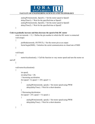
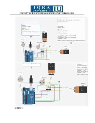
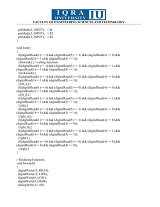
Code to serial control the DC motor speed.
const int motordc = 13; // Define the pin number to which the DC motor is connected
void setup()
{
pinMode(motordc, OUTPUT); // Set the motor pin as an output
Serial.begin(9600); // Initialize the serial communication at a baud rate of 9600
}
void loop()
{
// Serial control of motor speed
serialSpeed();
}
void serialSpeed()
{
int speed;
Serial.println("Type a speed (0-255) into the box above,");
Serial.println("then click [send] or press [return]");
Serial.println();
while (true)
{
while (Serial.available() > 0)
{
speed = Serial.parseInt(); // Read the speed value from the serial
monitor
speed = constrain(speed, 0, 255); // Ensure the speed value is within
the valid range
Serial.print("Setting speed to ");
Serial.println(speed);
analogWrite(motordc, speed); // Set the motor speed using PWM
}
}
}
78.
FACULTY OF ENGINEERINGSCIENCES AND TECHNOLOGY
Lecture:
PWM: Pulse Width Modulation is a technique to control analog signal by digitally
Signal is combination of voltage and current
Analog signal show and control digitally with the help of PWM.
Duty cycle: kitne dar tak waves chlti rahi .
Task
1. Control the speed of a DC motor by using PWM technique
Components Needed
1. Arduino board (e.g., Arduino Uno)
2. DC motor
3. NPN transistor (e.g., 2N2222 or TIP120) to handle the motor’s power requirements
4. Diode (e.g., 1N4007) to prevent back EMF from damaging the Arduino
5. Resistor (e.g., 220Ω or 330Ω) for the transistor base
6. External power supply (if the motor requires more power than the Arduino can suCODE:
const int motordc = 3; // Define the pin number to which the DC motor is connected
void setup()
{
pinMode(motordc, OUTPUT); // Set the motor pin as an output
Serial.begin(9600); // Initialize the serial communication at a baud rate of 9600
}
void loop()
{
motorOnThenOff(); // Call the function to turn the motor on and off
}
void motorOnThenOff()
{
int onTime = 3000; // Time the motor is kept ON in milliseconds (3 seconds)
int offTime = 3000; // Time the motor is kept OFF in milliseconds (3 seconds)
digitalWrite(motordc, HIGH); // Turn the motor ON by setting the motor pin to HIGH
delay(onTime); // Wait for the specified ON time
digitalWrite(motordc, LOW); // Turn the motor OFF by setting the motor pin to LOW
79.
FACULTY OF ENGINEERINGSCIENCES AND TECHNOLOGY
delay(offTime); // Wait for the specified OFF time
}
OR
FACULTY OF ENGINEERINGSCIENCES AND TECHNOLOGY
LINK:
https://www.tinkercad.com/things/6KkosSAuPo4-es-lab-7-dc-motor-p2?
sharecode=QV00VVDcFhohvevS4wBXJnemZzMSGpP9VKvfS6Lmil0
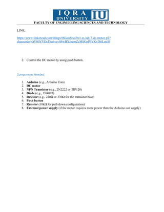
2. Control the DC motor by using push button.
Components Needed
1. Arduino (e.g., Arduino Uno)
2. DC motor
3. NPN Transistor (e.g., 2N2222 or TIP120)
4. Diode (e.g., 1N4007)
5. Resistor (e.g., 220Ω or 330Ω for the transistor base)
6. Push button
7. Resistor (10kΩ for pull-down configuration)
8. External power supply (if the motor requires more power than the Arduino can supply)
82.
FACULTY OF ENGINEERINGSCIENCES AND TECHNOLOGY
https://www.tinkercad.com/things/6KkosSAuPo4-es-lab-7-dc-motor-p2?
sharecode=QV00VVDcFhohvevS4wBXJnemZzMSGpP9VKvfS6Lmil0
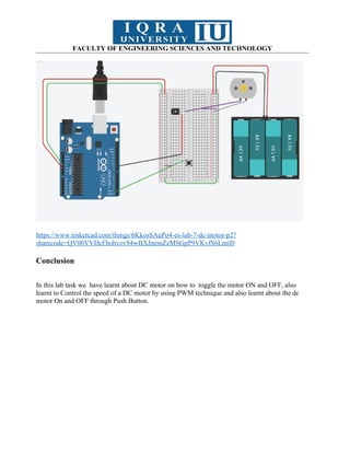
Conclusion
In this lab task we have learnt about DC motor on how to toggle the motor ON and OFF, also
learnt to Control the speed of a DC motor by using PWM technique and also learnt about the dc
motor On and OFF through Push Button.
83.
FACULTY OF ENGINEERINGSCIENCES AND TECHNOLOGY
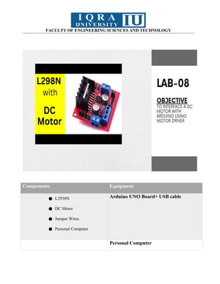
Components Equipment
● L2938N
● DC Motor
● Jumper Wires
● Personal Computer
Arduino UNO Board+ USB cable
Personal Computer
84.
FACULTY OF ENGINEERINGSCIENCES AND TECHNOLOGY
Basic Description
While you’ll eventually need to learn to control DC motors in order to build your own
robot, you’ll probably need something a little easier to get started – which is where the L298N
motor driver comes in. It can control the speed and spinning direction of two DC motors.
Controlling a DC Motor
We can only have full control over a DC motor if we can control its speed and spinning
direction. This is possible by combining these two techniques.
PWM – to control speed
H-Bridge – to control the spinning direction
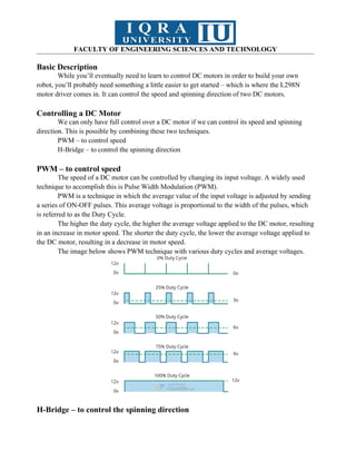
PWM – to control speed
The speed of a DC motor can be controlled by changing its input voltage. A widely used
technique to accomplish this is Pulse Width Modulation (PWM).
PWM is a technique in which the average value of the input voltage is adjusted by sending
a series of ON-OFF pulses. This average voltage is proportional to the width of the pulses, which
is referred to as the Duty Cycle.
The higher the duty cycle, the higher the average voltage applied to the DC motor, resulting
in an increase in motor speed. The shorter the duty cycle, the lower the average voltage applied to
the DC motor, resulting in a decrease in motor speed.
The image below shows PWM technique with various duty cycles and average voltages.
H-Bridge – to control the spinning direction
85.
FACULTY OF ENGINEERINGSCIENCES AND TECHNOLOGY
The spinning direction of a DC motor can be controlled by changing the polarity of its
input voltage. A widely used technique to accomplish this is to use an H-bridge.
An H-bridge circuit is made up of four switches arranged in an H shape, with the motor in
the center.
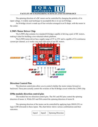
L298N Motor Driver Chip
The L298N chip contains two standard H-bridges capable of driving a pair of DC motors,
making it ideal for building a two-wheeled robotic platform.
The L298N motor driver has a supply range of 5V to 35V and is capable of 2A continuous
current per channel, so it works very well with most of our DC motors.
Direction Control Pins
The direction control pins allow you to control whether the motor rotates forward or
backward. These pins actually control the switches of the H-Bridge circuit within the L298N chip.
l298n module direction control pins
The module has two direction control pins. The IN1 and IN2 pins control the spinning
direction of motor A; While IN3 and IN4 control the spinning direction of motor B.
The spinning direction of the motor can be controlled by applying logic HIGH (5V) or
logic LOW (Ground) to these inputs. The chart below shows various combinations and their
outcomes.
Input1 Input2 Spinning Direction
86.
FACULTY OF ENGINEERINGSCIENCES AND TECHNOLOGY
Low(0) Low(0) Motor OFF
High(1) Low(0) Forward
Low(0)
High(1
)
Backward
High(1)
High(1
)
Motor OFF
Speed Control Pins
The speed control pins ENA and ENB are used to turn on/off the motors and control their
speed.
Pulling these pins HIGH will cause the motors to spin, while pulling them LOW will stop
them. However, with Pulse Width Modulation (PWM), the speed of the motors can be controlled.
The module usually comes with a jumper on these pins. When this jumper is in place, the motor
spins at full speed. If you want to control the speed of the motors programmatically, remove the
jumpers and connect them to the Arduino’s PWM-enabled pins.
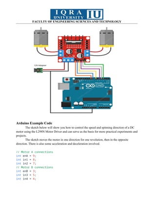
Circuit Diagram
Let’s begin by connecting the motor power supply. In our experiment, we are using DC
motors. They are rated for 3 to 12V. We will therefore connect an external 12V power source to
the VS terminal. Because L298N has a voltage drop of about 2V, the motors will receive 10V and
spin at a slightly lower RPM. But that’s okay.
Next, we need to supply 5V to the logic circuitry of the L298N. We’ll use the on-board 5V
regulator to draw 5V from the motor power supply, so keep the 5V-EN jumper in place.
Now connect the L298N module’s Input and Enable pins (ENA, IN1, IN2, IN3, IN4 and
ENB) to the six Arduino digital output pins (9, 8, 7, 5, 4 and 3). Note that both Arduino output pins
9 and 3 are PWM-enabled.
87.
FACULTY OF ENGINEERINGSCIENCES AND TECHNOLOGY
Arduino Example Code
The sketch below will show you how to control the speed and spinning direction of a DC
motor using the L298N Motor Driver and can serve as the basis for more practical experiments and
projects.
The sketch moves the motor in one direction for one revolution, then in the opposite
direction. There is also some acceleration and deceleration involved.
// Motor A connections
int enA = 9;
int in1 = 8;
int in2 = 7;
// Motor B connections
int enB = 3;
int in3 = 5;
int in4 = 4;
88.
FACULTY OF ENGINEERINGSCIENCES AND TECHNOLOGY
void setup() {
// Set all the motor control pins to outputs
pinMode(enA, OUTPUT);
pinMode(enB, OUTPUT);
pinMode(in1, OUTPUT);
pinMode(in2, OUTPUT);
pinMode(in3, OUTPUT);
pinMode(in4, OUTPUT);
// Turn off motors - Initial state
digitalWrite(in1, LOW);
digitalWrite(in2, LOW);
digitalWrite(in3, LOW);
digitalWrite(in4, LOW);
}
void loop() {
directionControl();
delay(1000);
speedControl();
delay(1000);
}
// This function lets you control spinning direction of motors
void directionControl() {
// Set motors to maximum speed
// For PWM maximum possible values are 0 to 255
analogWrite(enA, 255);
analogWrite(enB, 255);
// Turn on motor A & B
digitalWrite(in1, HIGH);
digitalWrite(in2, LOW);
digitalWrite(in3, HIGH);
digitalWrite(in4, LOW);
delay(2000);
// Now change motor directions
digitalWrite(in1, LOW);
digitalWrite(in2, HIGH);
89.
FACULTY OF ENGINEERINGSCIENCES AND TECHNOLOGY
digitalWrite(in3, LOW);
digitalWrite(in4, HIGH);
delay(2000);
// Turn off motors
digitalWrite(in1, LOW);
digitalWrite(in2, LOW);
digitalWrite(in3, LOW);
digitalWrite(in4, LOW);
}
// This function lets you control speed of the motors
void speedControl() {
// Turn on motors
digitalWrite(in1, LOW);
digitalWrite(in2, HIGH);
digitalWrite(in3, LOW);
digitalWrite(in4, HIGH);
// Accelerate from zero to maximum speed
for (int i = 0; i < 256; i++) {
analogWrite(enA, i);
analogWrite(enB, i);
delay(20);
}
// Decelerate from maximum speed to zero
for (int i = 255; i >= 0; --i) {
analogWrite(enA, i);
analogWrite(enB, i);
delay(20);
}
// Now turn off motors
digitalWrite(in1, LOW);
digitalWrite(in2, LOW);
digitalWrite(in3, LOW);
digitalWrite(in4, LOW);
}
FACULTY OF ENGINEERINGSCIENCES AND TECHNOLOGY
https://www.tinkercad.com/things/4qw24ZpzJLe-ahmer-lab-8-
practice?
sharecode=QaDyFrrbm8sbGpJGTcfAjH4W1M8eTZzs2PQRnReKcpo
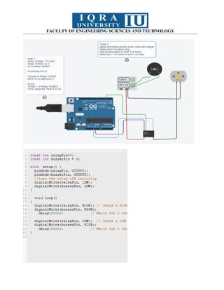
Task:
1--Control the DC Motor Using a Pushbutton
Use a pushbutton to start/stop a DC motor.(Slows down when the
button is pressed-does not stop completely)
The motor will run in a specific direction and stop when the button is
pressed again.
CODE:
FACULTY OF ENGINEERINGSCIENCES AND TECHNOLOGY
URL:
https://www.tinkercad.com/things/glYcQatQJst-dazzling-densor?sharecode=JEYheC98ANzpc-
AyqYYZKZdFjJGprG7U4A3ZAMollwU
97.
FACULTY OF ENGINEERINGSCIENCES AND TECHNOLOGY
2--Real-Life Application Project: Line-Following Robot
Objective:
Create a line-following robot that navigates a path using the concepts of
motor speed and direction control.
Project Requirements:
● Hardware:
o Arduino Uno
o L298N Motor Driver
o Two DC motors with wheels
o Chassis for the robot
o Infrared (IR) sensor module (for detecting lines)
o Power source for the motors
o Breadboard and connecting wires
● Software:
o Modify the provided code to integrate IR sensors for line
detection
Line Following Robot
Code:
void setup()
{
pinMode(13, OUTPUT); // Motor A +
pinMode(12, OUTPUT); // Motor A-
pinMode(11, OUTPUT); // Enable 1&2
pinMode(10, OUTPUT); // Enable 3&4
pinMode (9, OUTPUT); // Motor B -
pinMode (8, OUTPUT); // Motor B +
pinMode(6, INPUT); // L1
pinMode(5, INPUT); // L2
FACULTY OF ENGINEERINGSCIENCES AND TECHNOLOGY
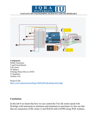
Component:
Hobby Gearmeter
3 small bread Board
5 IR sensor
9V Battery
H Bridge Motor Driver L293N
5v Regulator
Arduino Uno
Project Code:
https://www.tinkercad.com/things/7Jk0FmWssIp-daring-leelo-lappi
Conclusion:
In this lab 8 we learnt that how we can control the Two Dc motor speed with
H-bridge with maximum to minimum and minimum to maximum we also see that
that are connection of DC motor A and With B with LN2986 along With Arduino .
102.
FACULTY OF ENGINEERINGSCIENCES AND TECHNOLOGY
Components Equipment
● 2 Arduino UNO Board Arduino UNO Board+ USB cable
Personal Computer
103.
FACULTY OF ENGINEERINGSCIENCES AND TECHNOLOGY
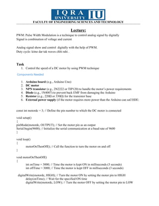
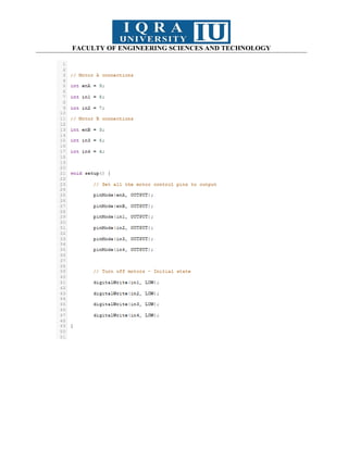
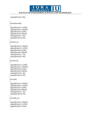
Basic Description
In this lab, you will learn how to perform the Serial Communication between two Arduino
boards. Although for most of the projects Arduino Uno or Arduino Mega is more than enough to
design advanced level projects like CNC machines, 3D Printers, etc. There are times when the
single Arduino Uno or Arduino Mega, or any other Arduino board is not enough to complete the
project, then in a situation like this you can Serial connect multiple Arduino boards. After doing
this experiment, you will be able how to use the Serial.read() and Serial.wrtie() functions. I will
start with the very basics and after you learn the basic concept of Serial communication, then I will
take it to the next level and we will do some advanced level things.
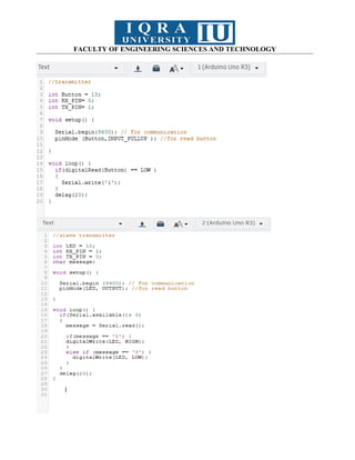
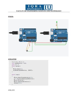
Circuit Diagram
You will only need three male to male type jumper wires to get started with the two
Arduino Boards. The RX of one Arduino Uno board is connected with the TX pin of the other
Arduino board and similarly the TX pin is connected with the RX pin of the other Arduino board.
Tx to Rx and Rx to Tx. Make sure the grounds of both the Arduino boards are connected together.
Serial Communication between Two Arduino Boards, Programming:
Now, to understand the concept of the serial communication between two Arduino boards,
let’s use one Arduino board as the Sender and the other Arduino board as the receiver. This means
we will need to write two programs, one for the Sender Arduino and the other for the Receiver
Arduino.
Sender Arduino Code:
char Mymessage[5] = "Hello"; //String data
void setup() {
104.
FACULTY OF ENGINEERINGSCIENCES AND TECHNOLOGY
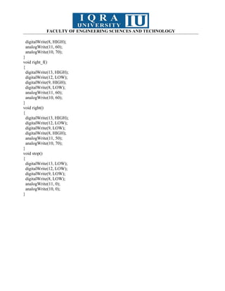
// Begin the Serial at 9600 Baud
Serial.begin(9600);
}
void loop() {
Serial.write(Mymessage,5); //Write the serial data
delay(1000);
}
Receiver Arduino Code:
char Mymessage[10]; //Initialized variable to store recieved data
void setup() {
// Begin the Serial at 9600 Baud
Serial.begin(9600);
}
void loop() {
105.
FACULTY OF ENGINEERINGSCIENCES AND TECHNOLOGY
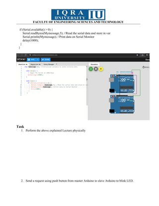
if (Serial.available() > 0) {
Serial.readBytes(Mymessage,5); //Read the serial data and store in var
Serial.println(Mymessage); //Print data on Serial Monitor
delay(1000);
}
}
Task
1. Perform the above explained Lecture physically
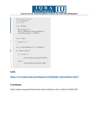
2. Send a request using push button from master Arduino to slave Arduino to blink LED.
106.
FACULTY OF ENGINEERINGSCIENCES AND TECHNOLOGY
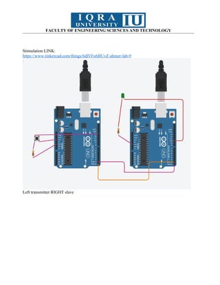
Stimulation LINK:
https://www.tinkercad.com/things/6dlVFo6BUvZ-ahmer-lab-9
Left transmitter RIGHT slave
FACULTY OF ENGINEERINGSCIENCES AND TECHNOLOGY
LINK
https://www.tinkercad.com/things/eLA47gfmhdL-redoof-ahmer-lab-9
Conclusion
Send a request using push button from master Arduino to slave Arduino to blink LED.
110.
FACULTY OF ENGINEERINGSCIENCES AND TECHNOLOGY
NAME: Muhammad Ahmer
ID: 15612
Course: Embedded System LAB
111.
FACULTY OF ENGINEERINGSCIENCES AND TECHNOLOGY
Components Equipment
● SPDT Relay,
● LEDs
● Resistor
● Diode
● Transistor
● Jump Wires
Arduino UNO Board+ USB cable
Personal Computer
Basic Description
This lab aims to familiarize the use of SPDT relays in embedded systems.
SPDT Relay
A relay is an electrically controlled mechanical switch used to control high-power devices. The
SPDT (Single Pole Double Throw) relay has the following terminals:
Common (COM): The moving part of the switch.
Normally Open (NO): The terminal connected when the relay is activated.
Normally Closed (NC): The terminal connected when the relay is deactivated.
Coil Terminals: Two terminals to which voltage is applied to energize the relay coil.
When DC voltage is applied to the coil terminals, the coil gets energized due to electromagnetism,
causing the switch to change its state from NC to NO.
FACULTY OF ENGINEERINGSCIENCES AND TECHNOLOGY
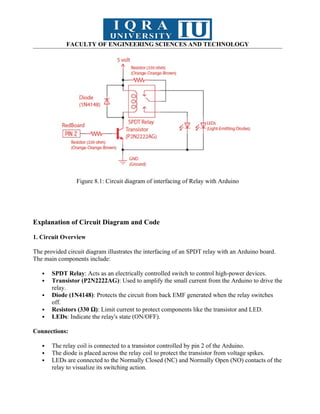
Figure 8.1: Circuit diagram of interfacing of Relay with Arduino
Explanation of Circuit Diagram and Code
1. Circuit Overview
The provided circuit diagram illustrates the interfacing of an SPDT relay with an Arduino board.
The main components include:
SPDT Relay: Acts as an electrically controlled switch to control high-power devices.
Transistor (P2N2222AG): Used to amplify the small current from the Arduino to drive the
relay.
Diode (1N4148): Protects the circuit from back EMF generated when the relay switches
off.
Resistors (330 Ω): Limit current to protect components like the transistor and LED.
LEDs: Indicate the relay's state (ON/OFF).
Connections:
The relay coil is connected to a transistor controlled by pin 2 of the Arduino.
The diode is placed across the relay coil to protect the transistor from voltage spikes.
LEDs are connected to the Normally Closed (NC) and Normally Open (NO) contacts of the
relay to visualize its switching action.
114.
FACULTY OF ENGINEERINGSCIENCES AND TECHNOLOGY
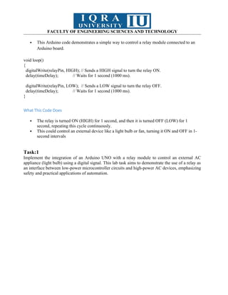
This Arduino code demonstrates a simple way to control a relay module connected to an
Arduino board.
void loop()
{
digitalWrite(relayPin, HIGH); // Sends a HIGH signal to turn the relay ON.
delay(timeDelay); // Waits for 1 second (1000 ms).
digitalWrite(relayPin, LOW); // Sends a LOW signal to turn the relay OFF.
delay(timeDelay); // Waits for 1 second (1000 ms).
}
What This Code Does
The relay is turned ON (HIGH) for 1 second, and then it is turned OFF (LOW) for 1
second, repeating this cycle continuously.
This could control an external device like a light bulb or fan, turning it ON and OFF in 1-
second intervals
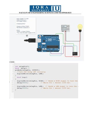
Task:1
Implement the integration of an Arduino UNO with a relay module to control an external AC
appliance (light bulb) using a digital signal. This lab task aims to demonstrate the use of a relay as
an interface between low-power microcontroller circuits and high-power AC devices, emphasizing
safety and practical applications of automation.
FACULTY OF ENGINEERINGSCIENCES AND TECHNOLOGY
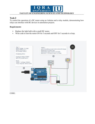
Task:2
To control the operation of a DC motor using an Arduino and a relay module, demonstrating how
relays can interface with DC devices in automation projects.
Requirements:
Replace the light bulb with a small DC motor.
Write code to turn the motor ON for 5 seconds and OFF for 5 seconds in a loop.
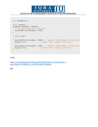
CODE:
117.
FACULTY OF ENGINEERINGSCIENCES AND TECHNOLOGY
LINK:
https://www.tinkercad.com/things/jdFIw8qFaWt-lab-10-es?sharecode=i-
auzq7QpJUNA52fihZ3yu-_6zsCsYRv4Kc79nQ8dHs
OR
FACULTY OF ENGINEERINGSCIENCES AND TECHNOLOGY
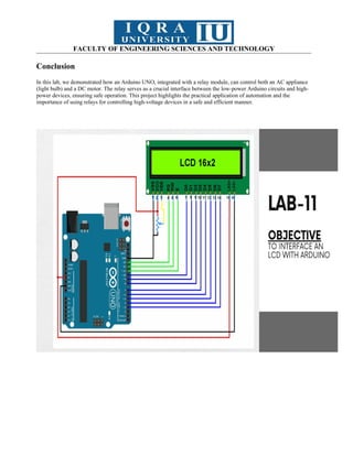
Conclusion
In this lab, we demonstrated how an Arduino UNO, integrated with a relay module, can control both an AC appliance
(light bulb) and a DC motor. The relay serves as a crucial interface between the low-power Arduino circuits and high-
power devices, ensuring safe operation. This project highlights the practical application of automation and the
importance of using relays for controlling high-voltage devices in a safe and efficient manner.
120.
FACULTY OF ENGINEERINGSCIENCES AND TECHNOLOGY
Components Equipment
● 16x2 LCD
● LEDs
● Jump Wires
Arduino UNO Board+ USB cable
Personal Computer
121.
FACULTY OF ENGINEERINGSCIENCES AND TECHNOLOGY
Basic Description
An LCD, or liquid crystal display, is a simple screen that can display commands, bits of
information, or readings from your sensor - all depending on how you program your board. In this
circuit, you’ll learn the basics of incorporating an LCD into your project. We are using a 16×2
LCD in this experiment. By 16×2, we mean 16 characters and 2 lines. Displaying your required
data on any position of the LCD will be described by the instructor.
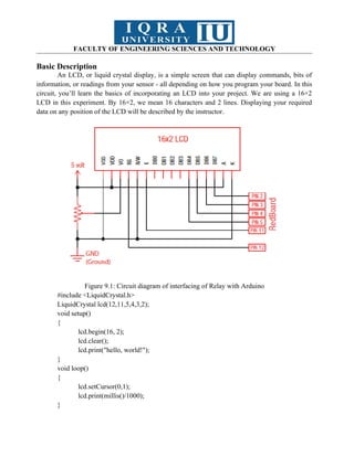
Figure 9.1: Circuit diagram of interfacing of Relay with Arduino
#include <LiquidCrystal.h>
LiquidCrystal lcd(12,11,5,4,3,2);
void setup()
{
lcd.begin(16, 2);
lcd.clear();
lcd.print("hello, world!");
}
void loop()
{
lcd.setCursor(0,1);
lcd.print(millis()/1000);
}
122.
FACULTY OF ENGINEERINGSCIENCES AND TECHNOLOGY
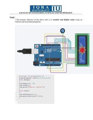
Task:
1.The primary objective of the above task is to monitor and display name using an
Arduino and associated peripherals.
123.
FACULTY OF ENGINEERINGSCIENCES AND TECHNOLOGY
LINK: https://www.tinkercad.com/things/lm2Nshm5mZE-mahmer-lab-10-task-1
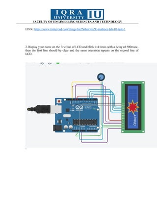
2.Display your name on the first line of LCD and blink it 4 times with a delay of 500msec,
then the first line should be clear and the same operation repeats on the second line of
LCD.
’
124.
FACULTY OF ENGINEERINGSCIENCES AND TECHNOLOGY
LINK:
https://www.tinkercad.com/things/fG5BYBfb6RO-mahmer-lab-10-task-2?
sharecode=VMm--p4wmTWmaV4xGfu9wkF8QYcBuKbl79Iy8kejF2g
Conclusion:


![FACULTY OF ENGINEERING SCIENCES AND TECHNOLOGY
char notes[] = "cdfda ag cdfdg gf";
int beats[] = {1, 1, 1, 1, 1, 1, 4, 4, 2, 1, 1, 1, 1, 1, 1, 1, 4, 4};
int tempo = 150;
void setup()
{
pinMode(buzzer, OUTPUT);
}
void loop()
{
int i, duration;
for (i = 0; i < songlength; i++) {
duration = beats[i] * tempo;
if (notes[i] == ' ') {
delay(duration);
} else {
tone(buzzer, frequency(notes[i]), duration);
delay(duration);
}
delay(tempo / 10);
}
}
int frequency(char note) {
int i;
const int numNotes = 8;
char names[] = {'c', 'd', 'e', 'f', 'g', 'a', 'b', 'C'};
int frequencies[] = {262, 294, 330, 349, 392, 440, 494, 523};
for (i = 0; i < numNotes; i++) {
if (names[i] == note) {
return frequencies[i]; // Yes! Return the frequency
}
}
return 0;
}](https://image.slidesharecdn.com/areebafatimaembeddedmanual-250610202334-2db8d60a/85/embedded-manual-for-students-to-learn-and-do-61-320.jpg)
![FACULTY OF ENGINEERING SCIENCES AND TECHNOLOGY
Code to serial control the DC motor speed.
const int motordc = 13; // Define the pin number to which the DC motor is connected
void setup()
{
pinMode(motordc, OUTPUT); // Set the motor pin as an output
Serial.begin(9600); // Initialize the serial communication at a baud rate of 9600
}
void loop()
{
// Serial control of motor speed
serialSpeed();
}
void serialSpeed()
{
int speed;
Serial.println("Type a speed (0-255) into the box above,");
Serial.println("then click [send] or press [return]");
Serial.println();
while (true)
{
while (Serial.available() > 0)
{
speed = Serial.parseInt(); // Read the speed value from the serial
monitor
speed = constrain(speed, 0, 255); // Ensure the speed value is within
the valid range
Serial.print("Setting speed to ");
Serial.println(speed);
analogWrite(motordc, speed); // Set the motor speed using PWM
}
}
}](https://image.slidesharecdn.com/areebafatimaembeddedmanual-250610202334-2db8d60a/85/embedded-manual-for-students-to-learn-and-do-77-320.jpg)


![FACULTY OF ENGINEERING SCIENCES AND TECHNOLOGY
Basic Description
In this lab, you will learn how to perform the Serial Communication between two Arduino
boards. Although for most of the projects Arduino Uno or Arduino Mega is more than enough to
design advanced level projects like CNC machines, 3D Printers, etc. There are times when the
single Arduino Uno or Arduino Mega, or any other Arduino board is not enough to complete the
project, then in a situation like this you can Serial connect multiple Arduino boards. After doing
this experiment, you will be able how to use the Serial.read() and Serial.wrtie() functions. I will
start with the very basics and after you learn the basic concept of Serial communication, then I will
take it to the next level and we will do some advanced level things.
Circuit Diagram
You will only need three male to male type jumper wires to get started with the two
Arduino Boards. The RX of one Arduino Uno board is connected with the TX pin of the other
Arduino board and similarly the TX pin is connected with the RX pin of the other Arduino board.
Tx to Rx and Rx to Tx. Make sure the grounds of both the Arduino boards are connected together.
Serial Communication between Two Arduino Boards, Programming:
Now, to understand the concept of the serial communication between two Arduino boards,
let’s use one Arduino board as the Sender and the other Arduino board as the receiver. This means
we will need to write two programs, one for the Sender Arduino and the other for the Receiver
Arduino.
Sender Arduino Code:
char Mymessage[5] = "Hello"; //String data
void setup() {](https://image.slidesharecdn.com/areebafatimaembeddedmanual-250610202334-2db8d60a/85/embedded-manual-for-students-to-learn-and-do-103-320.jpg)
![FACULTY OF ENGINEERING SCIENCES AND TECHNOLOGY
// Begin the Serial at 9600 Baud
Serial.begin(9600);
}
void loop() {
Serial.write(Mymessage,5); //Write the serial data
delay(1000);
}
Receiver Arduino Code:
char Mymessage[10]; //Initialized variable to store recieved data
void setup() {
// Begin the Serial at 9600 Baud
Serial.begin(9600);
}
void loop() {](https://image.slidesharecdn.com/areebafatimaembeddedmanual-250610202334-2db8d60a/85/embedded-manual-for-students-to-learn-and-do-104-320.jpg)