Exp. No.01 Date:
INTRODUCTIONTO ARDUINO
AIM : To study the Introduction and Installation of Arduino.
Arduino is a prototype platform (open-source) based on an easy-to-use hardware and
software. It consists of a circuit board, which can be programed (referred to as a
microcontroller) and a ready-made software called Arduino IDE (Integrated Development
Environment), which is used to write and upload the computer code to the physical board.
The key features are −
• Arduino boards are able to read analog or digital input signals from different sensors
and turn it into an output such as activating a motor, turning LED on/off, connect to the
cloud and many other actions.
• You can control your board functions by sending a set of instructions to the
microcontroller on the board via Arduino IDE (referred to as uploading software).
• Unlike most previous programmable circuit boards, Arduino does not need an extra
piece of hardware (called a programmer) in order to load a new code onto the board.
You can simply use a USB cable.
• Additionally, the Arduino IDE uses a simplified version of C++, making it easier to
learn to program.
• Finally, Arduino provides a standard form factor that breaks the functions of the micro-
controller into a more accessible package.
Board Types
Various kinds of Arduino boards are available depending on different microcontrollers
used. However, all Arduino boards have one thing in common: they are programed through the
Arduino IDE.
The differences are based on the number of inputs and outputs (the number of sensors, LEDs,
and buttons you can use on a single board), speed, operating voltage, form factor etc. Some
boards are designed to be embedded and have no programming interface (hardware), which
you would need to buy separately. Some can run directly from a 3.7V battery, others need at
least
Here is alist of different Arduino boards available.
Arduino boards based on ATMEGA328 microcontroller
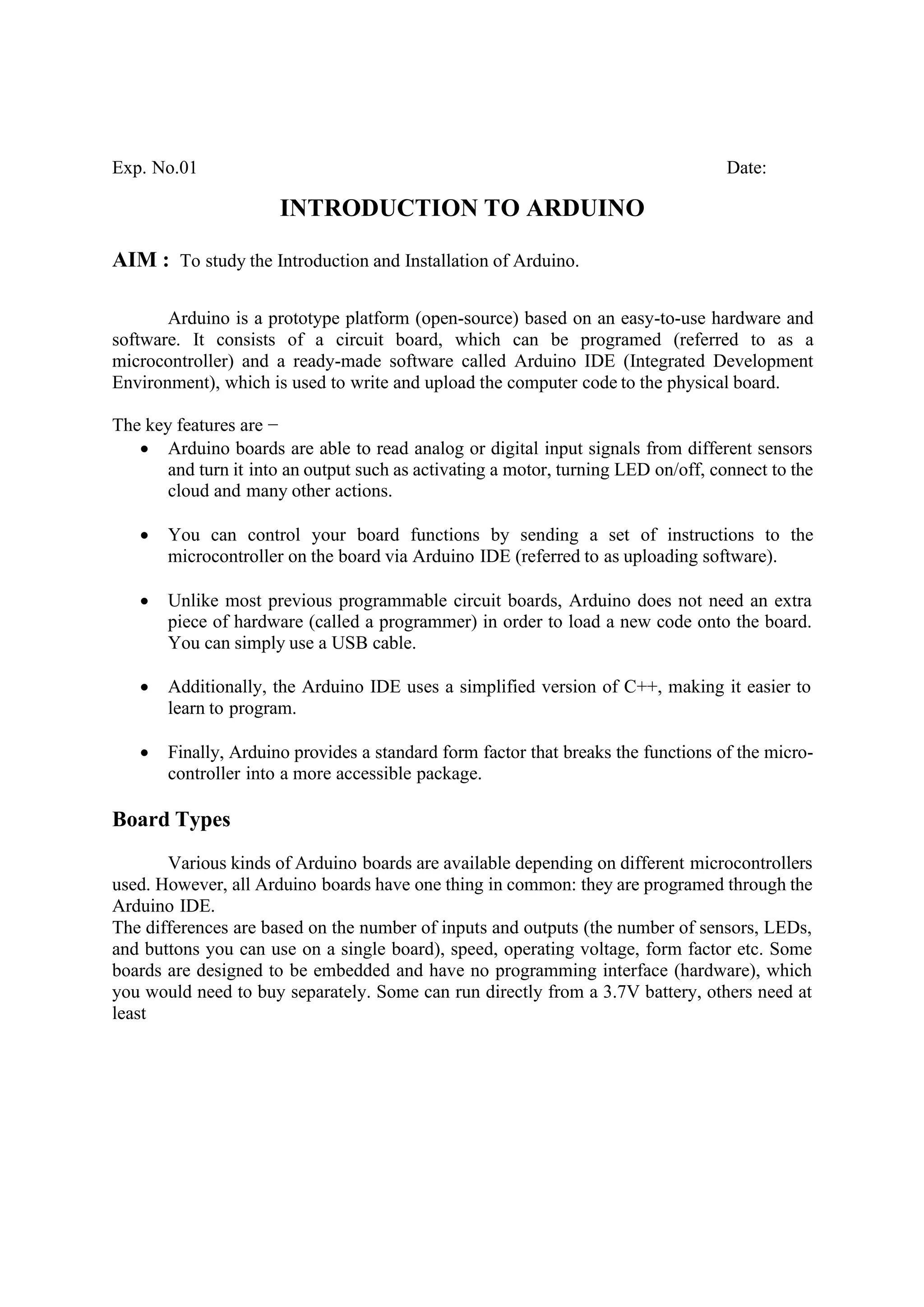
Arduino UNO - Board Description
In this chapter, we will learn about the different components on the Arduino board. We
will study the Arduino UNO board because it is the most popular board in the Arduino board
family. In addition, it is the best board to get started with electronics and coding. Some boards
look a bit different from the one given below, but most Arduinos have majority of these
components in common.
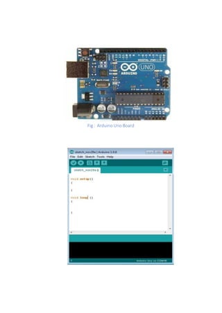
Power USB
Arduino boardcan be powered by using the USB cable from your computer. All youneed to
do is connect the USB cable to the USB connection (1).
Power (Barrel Jack)
Arduino boards can be powered directly from the AC mains power supply by connecting it to
the Barrel Jack (2).
Voltage Regulator
The function of the voltage regulator is to control the voltage given to the Arduino board and
stabilize the DC voltages used by the processor and other elements.
Crystal Oscillator
The crystal oscillator helps Arduino in dealing with time issues. How does Arduino calculate time? The
answer is, by using the crystal oscillator. The number printed on top of the Arduinocrystal is 16.000H9H. It
tells us that the frequency is 16,000,000 Hertz or 16 MHz.
Arduino Reset
You can reset your Arduino board, i.e., start your program from the beginning. You can reset the UNO
board in two ways. First, by using the reset button (17) on the board. Second, you can connect an external
reset button to the Arduino pin labelled RESET (5).
Pins (3.3, 5, GND, Vin)
• 3.3V (6) − Supply 3.3 output volt
• 5V (7) − Supply 5 output volt
• Most of the components used with Arduino board works fine with 3.3 volt and 5volt.
• GND (8)(Ground) − There are several GND pins on the Arduino, any of which can be
used to ground your circuit.
• Vin(9) − This pin also can be used to power the Arduino board froman external power
source, like AC mains power supply.
Analog pins
The Arduino UNO board has six analog input pins A0 through A5. These pins can read the
signal from an analog sensor like the humidity sensor or temperature sensor and convert it
into a digital value that can be read by the microprocessor.
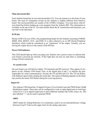
Main microcontroller
Each Arduinoboard has its own microcontroller (11). You can assume it as the brain of your
board. The main IC (integrated circuit) on the Arduino is slightly different from board to
board. The microcontrollers are usually of the ATMEL Company. You must know what IC
your board has before loading up a new program from the Arduino IDE. This information is
available on the top of the IC. For more details about the IC construction and functions, you
can refer to the data sheet.
ICSP pin
Mostly, ICSP (12) is an AVR, a tiny programming header for the Arduino consisting of MOSI,
MISO, SCK, RESET, VCC, and GND. It is often referred to as an SPI (Serial Peripheral
Interface), which could be considered as an "expansion" of the output. Actually, you are
slaving the output device to the master of the SPI bus.
Power LED indicator
This LED should light up when you plug your Arduino into a power source to indicate that
your board is powered up correctly. If this light does not turn on, then there is something
wrong with the connection.
TX and RX LEDs
On your board, you will find two labels: TX (transmit) and RX (receive). They appear in two
places on the Arduino UNO board. First, at the digital pins 0 and 1, to indicate the pins
responsible for serial communication. Second, the TX and RX led (13). The TX led flashes
with different speed while sending the serial data. The speed of flashing depends on the baud
rate used by the board. RX flashes during the receiving process.
Digital I/O
The Arduino UNO board has 14 digital I/O pins (15) (of which 6 provide PWM (Pulse Width
Modulation) output. These pins can be configured to work as input digital pins to read logic
values (0 or 1) or as digital output pins to drive different modules like LEDs, relays, etc. The
pins labelled “~” can be used to generate PWM.
AREF
AREF stands for Analog Reference. It is sometimes, used to set an externalreference voltage
(between 0 and 5 Volts) as the upper limit for the analog input pins.
9.
Arduino IDE –Installation
After learning about the main parts of the Arduino UNO board, we are ready to learn
how to setup the Arduino IDE. Once we learn this, we will be ready to upload our program on
the Arduino board.
In this section, we will learn in easy steps, how to set up the Arduino IDE on our computer and
prepare the board to receive the program via USB cable.
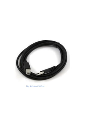
Step 1
First you must have your Arduino board (you can choose your favourite board) and a USB
cable. In case you use Arduino UNO, Arduino Duemilanove, Nano, Arduino Mega 2560, or
Diecimila, you will need a standard USB cable (A plug to B plug), the kind you would connect
to a USB printer as shown in the following image.
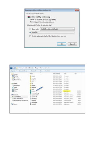
Step 2 − Download Arduino IDE Software.
You can get different versions of Arduino IDE from the Download page on the Arduino
Official website. You must select your software, which is compatible with your operating
system (Windows, IOS, or Linux). After your file download is complete, unzip the file
Step 3 − Power up your board.
The Arduino Uno, Mega, Duemilanove and Arduino Nano automatically draw power from
either, the USB connection to the computer or an external power supply. If you are using an
Arduino Diecimila, you have to make sure that the board is configured to draw power from the
USB connection. The power source is selected with a jumper, a small piece of plastic that fits
onto two of the three pins between the USB and power jacks. Check that it is on the two pins
closest to the USB port.
Connect the Arduino board to your computer using the USB cable. The green power LED
(labeled PWR) should glow.
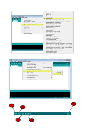
Step 4 − Launch Arduino IDE.
After your Arduino IDE software is downloaded, you need to unzip the folder. Inside the folder,
you can find the application icon with an infinity label (application.exe). Double-click the icon
to start the IDE.
Step 5 − Open your first project.
Once the software starts, you have two options −
Create a new project.
Open an existing project example
To create a new project, select File → New.
To open anexisting project example, select File → Example → Basics → Blink.
Here, we are selecting just one of the examples with the name Blink. It turns the LED on and
off with some time delay. You can select any other example from the list.
Step 6 − Select your Arduino board.
To avoid any error while uploading your program to the board, you must select the correct
Arduino board name, which matches with the board connected to your computer.
Go to Tools → Board and select your board.
Here, we have selected Arduino Uno board according to our tutorial, but you must select the
name matching the board that you are using.
Step 7 − Select your serial port.
Select the serial device of the Arduino board. Go to Tools → Serial Port menu. This is likely
to be COM3 or higher (COM1 and COM2 are usually reserved for hardware serial ports). To
findout, you can disconnect your Arduino board and re-open the menu, the entry that disappears
should be of the Arduino board. Reconnect the board and select that serial port.
Step 8 − Upload the program to your board.
Before explaining how we can upload our program to the board, we must demonstrate the
function of each symbol appearing in the Arduino IDE toolbar.
13.
A − Usedto check if there is any compilation error.
B − Used to upload a program to the Arduino board.
C − Shortcut used to create a new sketch.
D − Used to directly open one of the example sketch.
E − Used to save your sketch.
F − Serial monitor used to receive serial data from the board and send the serial data to the
board.
Now, simply click the "Upload" button in the environment. Wait a few seconds; you will see
the RX and TX LEDs on the board, flashing. If the upload is successful, the message "Done
uploading" will appear in the status bar.
Note − If you have an Arduino Mini, NG, or other board, you need to press the reset button
physically on the board, immediately before clicking the upload button on the Arduino
Software.
RESULT:
15.
JNTUK UNIVERSITY COLLEGEOF ENGINEERING NARASARAOPET
Exp. No.02 Date:
BLINKING AN LED
AIM:
To blink an LED for the given amount of time using Arduino.
HARDWARE REQUIRED:
• Arduino Board
• LED
• 220 ohm resistor
SOFTWARE REQUIRED:
• Arduino IDE
DESCRIPTION:
This experiment uses the built-in LED that most Arduino boards have. This LED is
connected to a digital pin and its number may vary from board type to board type.
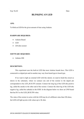
If we want to light an external LED with this sketch, we need to build the circuit as
shown in the schematic, where we connect one end of the resistor to the digital pin
correspondent to the LED_BUILTIN constant. Connect the long leg of the LED (the positive
leg, called the anode) to the other end of the resistor. Connect the short leg of the LED (the
negative leg, called the cathode) to the GND. In the diagram below we show an UNO board
that has D13 as the LED_BUILTIN value.
The value of the resistor in series with the LED may be of a different value than 220 ohms;
the LED will light up also with values up to 1K ohm.
JNTUK UNIVERSITY COLLEGEOF ENGINEERING NARASARAOPET
CODE:
Blinking built-in LED:
// the setup function runs once when you press reset or power the board
void setup()
{
// initialize digital pin LED_BUILTIN as an output.
pinMode(LED_BUILTIN, OUTPUT);
}
// the loop function runs over and over again forever
void loop()
{
digitalWrite(LED_BUILTIN, HIGH); // turn the LED on (HIGH is the voltage level)
delay(1000); // wait for a second
digitalWrite(LED_BUILTIN, LOW); // turn the LED off by making the voltage LOW
delay(1000); // wait for a second
}
Blinking external LED:
int led = 13; // set the "led" variable as 13
void setup() {
pinMode(led, OUTPUT); // designate port 13 as output
}
void loop() {
digitalWrite(led, HIGH); // turn the led on
delay(1000); // wait for 1 second
digitalWrite(led, LOW); // turn the led off
delay(1000); // wait for a second
}
JNTUK UNIVERSITY COLLEGEOF ENGINEERING NARASARAOPET
CODE DESCRIPTION:
After the circuit connections are done, plug the Arduino board into computer, start
the Arduino Software (IDE) and enter the code below. We may also load it from the menu
File/Examples/01.Basics/Blink. The first thing to do is to initialize LED_BUILTIN pin as an
output pin with the line
pinMode(LED_BUILTIN, OUTPUT);
In the main loop, we turn the LED on with the line:
digitalWrite(LED_BUILTIN, HIGH);
This supplies 5 volts to the LED anode. That creates a voltage difference across the pins of
the LED, and lights it up. Then we turn it off with the line:
digitalWrite(LED_BUILTIN, LOW);
That takes the LED_BUILTIN pin back to 0 volts, and turns the LED off. In between the on
and the off, we want enough time for a person to see the change, so the delay() commands
tell the board to do nothing for 1000 milliseconds, or one second. When we use the delay()
command, nothing else happens for that amount of time. Change the delay and observe the
LED turning ON and OFF for the given amount of delay.
PROCEDURE:
• Connect the circuit as shown in the circuit diagram.
• Connect the Arduino board to the Laptop or PC.
• Open Arduino IDE and click on tools→ port to select the corresponding communication
port.
• Write the code and click on verify/compile to check the errors.
• To upload the code click on upload and wait for the response.
• Verify the results.
RESULT:
29.
JNTUK UNIVERSITY COLLEGEOF ENGINEERING NARASARAOPET
Exp no:- Date:-
TEMPERATURE AND HUMIDITY MEASUREMENT USING
ARDUINO UNO AND DHT SENSOR
AIM:
To detect the temperature and humidity by using Arduino UNO and DHT-11 sensor.
HARDWARE REQUIREMENTS:
• Arduino UNO
• Breadboard
• Connecting wires
• DHT-11 sensor
• USB-A to B cable
SOFTWARE REQUIREMENTS:
• Arduino IDE
THEORY:
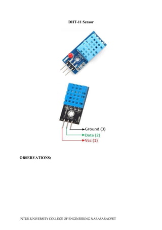
DHT-11 SENSOR:
The DHT11 is a commonly used Temperature and humidity sensor. The sensor
comes with a dedicated NTC to measure temperature and humidity. The sensor is also factory
calibrated and hence easy to interface with other microcontrollers.
The DHT11 sensor can either be purchased as a sensor or as a module. Either way, the
performance of the sensor is same. The sensor will come as a 4-pin package out of which only
three pins will be used whereas the module will come with three pins.
The sensor can measure temperature from 0°C to 50°C and humidity from 20% to 90%
with an accuracy of ±1°C and ±1%.
• Operating Voltage: 3.5V to 5.5V
• Temperature Range: 0°C to 50°C
• Humidity Range: 20% to 90%
• Accuracy: ±1°C and ±1%
JNTUK UNIVERSITY COLLEGEOF ENGINEERING NARASARAOPET
ARDUINO UNO:
Arduino UNO is a microcontroller board based on the ATmega328P. It has 14 digital
input/output pins (of which 6 can be used as PWM outputs), 6 analog inputs, a 16 MHz
ceramic resonator, a USB connection, a power jack, an ICSP header, and a reset button. It
contains everything needed to support the microcontroller; simply connect it to a computer
with a USB cable or power it with an AC-to-DC adapter or battery to get started.
LED:
In the simplest terms, a light-emitting diode (LED) is a semiconductor device that emits
light when an electric current is passed through it. Light is produced when the particles that
carry the current (known as electrons and holes) combine together within the semiconductor
material. Led has two terminals : positive and negative.
CIRCUIT DESCRIPTION:
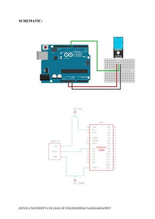
Connection of DHT-11 sensor:
The interfacing of the DHT11 temperature and humidity sensor with the Arduino UNO
board is shown in Figure. Pins 1, 2, and 3 of DHT11 are connected to the 5 V, A0, and GND
(ground) pins of the Arduino board. Pin 2 of the DHT11 sensor sends out the measured
humidity and temperature value, and it is connected to the analog input A0 pin of the Arduino
UNO board.
CODE:
#include <dht.h>
dht DHT;
int analogInput=A0;
void setup()
{
pinMode(analogInput,INPUT);
Serial.begin(9600);
}
void loop()
{
DHT.read11(A0);
Serial.print("Humidity= ");
Serial.print(DHT.humidity);
Serial.println("%");
JNTUK UNIVERSITY COLLEGEOF ENGINEERING NARASARAOPET
Serial.print("temperature= ");
Serial.print(DHT.temperature);
Serial.println("°C ");
delay(1000);
}
CODE DESCRIPTION:
The statement (1) #include <dht.h> includes the DHT library. The DHT library has all
the functions required to get the humidity and temperature readings from the sensor. The DHT
library is not part of in-built Arduino libraries; rather, we must include it. For including the dht
library, we download the DHTLLib.zip file and copy the DHT library into the Arduino Library
folder. The statement (2) dht DHT creates an object of the name DHT. We can create an object
of any name. The statements (3) and (4) initialize the analog input pin A0 as “analogInput”,
which is initialized as an input pin.
Statement (5) initializes the serial communication between the Arduino UNO board and
the computer to display the serial monitor at 9,600 baud. The statement (6) DHT.read11(A0)
reads the value of humidity and temperature from analog pin A0 and assigns its value to object
DHT. T+he humidity value can be accessed by the DHT.humidity function, and the
temperature value can be accessed by the DHT.temperature function.
The statements from (6) to (13) are used to display the humidity value in % and temperature
value in °C in the serial monitor after every 2 seconds.
PROCEDURE:
• Connect the circuit as shown in the circuit diagram.
• Connect the Arduino board to the laptop or PC.
• Open Arduino IDE and click on tools and then port to select the corresponding
communication port.
• Write the code and click on verify/compile to check the errors.
• To upload the code, click on upload and wait for the response.
• Verify the results.
RESULT:
35.
JNTUK UNIVERSITY COLLEGEOF ENGINEERING NARASARAOPET
Exp No: Date:
SMOKE DETECTION USING MQ2 SENSOR AND
ARDUINO UNO
AIM:
To implement the smoke detection using MQ2 sensor and Arduino UNO.
HARDWARE REQUIRED:
• Arduino UNO
• MQ 2 sensor
• Resistors -3
• LED - 2
• Connecting wires
• USB-A to B Cable
• Bread Board
• Buzzer
SOFTWARE REQUIRED:
• Arduino IDE
THEORY:
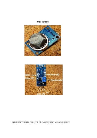
The MQ-2 smoke sensor is sensitive to smoke and to the following flammable gases:
• LPG
• Butane
• Propane
• Methane
• Alcohol
• Hydrogen
The resistance of the sensor is different depending on the type of the gas. The smoke sensor
has a built-in potentiometer that allows you to adjust the sensor sensitivity according to how
accurate you want to detect gas.
JNTUK UNIVERSITY COLLEGEOF ENGINEERING NARASARAOPET
The voltage that the sensor outputs changes accordingly to the smoke/gas level that exists in
the atmosphere. The sensor outputs a voltage that is proportional to the concentration of
smoke/gas.
In other words, the relationship between voltage and gas concentration is the following:
• The greater the gas concentration,the greater the output voltage
• The lower the gas concentration,the lower the output voltage
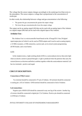
The output can be an analog signal (A0) that can be read with an analog input of the Arduino
or a digital output (D0) that can be read with a digital input of the Arduino.
Arduino Uno :
The Arduino Uno is a microcontroller board based on the ATmega328. It has 20 digital
input/output pins (of which 6 can be used as PWM outputs and 6 can be used as analog inputs),
a 16 MHz resonator, a USB connection, a power jack, an in-circuit system programming
(ICSP) header, and a reset button.
LED:
In the simplest terms, a light-emitting diode (LED) is a semiconductor device that emits light
when an electric current is passed through it. Light is produced when the particles that carry the
current (known as electrons and holes) combine together within the semiconductor material. Led
has two terminals : positive and negati
CIRCUIT DESCRIPTION:
Connections of MQ-2 sensor :
Vcc terminal should be connected to 5V pin of Arduino. A0 terminal should be connected
to analog pin (A5) of Arduino GND terminal should be connected to Gnd of Arduino.
Led connections :
Negative pin of RED LED should be connected to any one leg of the resistor. Another leg
of resistor should be connected to digital pin 12 of Arduino. Positive pin should be connected
to GND pin of Arduino.
JNTUK UNIVERSITY COLLEGEOF ENGINEERING NARASARAOPET
Negative pin of GREEN LED should be connected to any one leg of the resistor. Another
leg of resistor should be connected to pin 11 of Arduino. Positive pin connected to GND.
BUZZER connections:
Positive terminal connected to pin 10 of Arduino. Negative pin of Buzzer is given to the
one leg of the resistor and another leg of resistor is connected to the GND.
SOURCE CODE:
int redLed = 12;
int greenLed = 11;
int buzzer = 10;
int smokeA0 = A5;
// Your threshold value
int sensorThres = 400;
void setup() {
pinMode(redLed, OUTPUT);
pinMode(greenLed, OUTPUT);
pinMode(buzzer, OUTPUT);
pinMode(smokeA0, INPUT);
Serial.begin(9600);
}
void loop() {
int analogSensor = analogRead(smokeA0);
Serial.print("Pin A0: ");
Serial.println(analogSensor);
// Checks if it has reached the threshold value
if (analogSensor > sensorThres)
{
digitalWrite(redLed, HIGH);
digitalWrite(greenLed, LOW);
tone(buzzer, 1000, 200);
}
else
{
digitalWrite(redLed, LOW);
digitalWrite(greenLed, HIGH);
noTone(buzzer);
}
delay(100);
}
JNTUK UNIVERSITY COLLEGEOF ENGINEERING NARASARAOPET
CODE DESCRIPTION:
• Begin the serial communication by using the function "Serial.begin()".
• Set the baud rate as 9600. Then set the digital pin 12 as a "redLed" pin.Set the pin 11 as
a “greenLed” and set pin 10 as “buzzer”.Set pin A5 to “smokeA0”.
• Set sensor threshold(“sensorThres”) to 400
• When the sensor does not detect any smoke then the GREEN led is turned ON and
when smoke is detected RED led and BUZZER gets turned ON .
• We can observe smoke concentration values in the SERIAL MONITOR.
• Note: The threshold value is varying from one application to another. Here
‘sensorThres’ in the above program can vary when circuit is changed.
PROCEDURE:
• Connect the circuit as shown in the circuit diagram
• Connect the Arduino board to the laptop or PC
• Open Arduino IDE and click on tools and then port to select the corresponding
communication port.
• Write the code and click on verify/compile to check the errors.
• To upload the code click on upload and wait for the response.
• Verify the results.
RESULT:
43.
Exp no: Date:
ObjectDetection Using IR Sensor With Arduino UNO
AIM:
To interface IR sensor with Arduino UNO for object detection.
HARDWARE REQUIRED:
• Arduino UNO Board
• IR sensor
• LED
• Resistors (1k ohms)
• Jumper wires
• Bread Board
• USB Cable
SOFTWARE REQUIRED:
• Arduino IDE
Theory:
IR Sensor :
An infrared sensor is an electronic device, that emits in order to sense some aspects
of the surroundings. An IR sensor can measure the heat of an object as well as detects
the motion. These types of sensors measures only infrared radiation, rather than
emitting it that is called as a passive IR sensor.
SCHEMATIC:
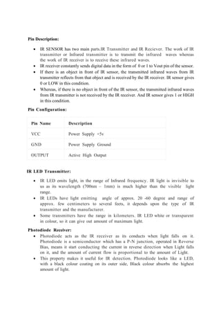
Pin Description:
• IRSENSOR has two main parts.IR Transmitter and IR Reciever. The work of IR
transmitter or Infrared transmitter is to transmit the infrared waves whereas
the work of IR receiver is to receive these infrared waves.
• IR receiver constantly sends digital data in the form of 0 or 1 to Vout pin of the sensor.
• If there is an object in front of IR sensor, the transmitted infrared waves from IR
transmitter reflects from that object and is received by the IR receiver. IR sensor gives
0 or LOW in this condition.
• Whereas, if there is no object in front of the IR sensor, the transmitted infrared waves
from IR transmitter is not received by the IR receiver. And IR sensor gives 1 or HIGH
in this condition.
Pin Configuration:
Pin Name Description
VCC Power Supply +5v
GND Power Supply Ground
OUTPUT Active High Output
IR LED Transmitter:
• IR LED emits light, in the range of Infrared frequency. IR light is invisible to
us as its wavelength (700nm – 1mm) is much higher than the visible light
range.
• IR LEDs have light emitting angle of approx. 20 -60 degree and range of
approx. few centimeters to several feets, it depends upon the type of IR
transmitter and the manufacturer.
• Some transmitters have the range in kilometers. IR LED white or transparent
in colour, so it can give out amount of maximum light.
Photodiode Receiver:
• Photodiode acts as the IR receiver as its conducts when light falls on it.
Photodiode is a semiconductor which has a P-N junction, operated in Reverse
Bias, means it start conducting the current in reverse direction when Light falls
on it, and the amount of current flow is proportional to the amount of Light.
• This property makes it useful for IR detection. Photodiode looks like a LED,
with a black colour coating on its outer side, Black colour absorbs the highest
amount of light.
CODE:
#include<SoftwareSerial.h>
int greenLed =11;
int buzzer = 10;
int out = A0;
// Your threshold value
int sensorThres = 400;
int count=0;
void setup() {
pinMode(greenLed, OUTPUT);
pinMode(buzzer, OUTPUT);
pinMode(out, INPUT);
Serial.begin(9600);
}
void loop() {
int analogSensor = analogRead(out);
// Checks if it has reached the threshold value
if (analogSensor > sensorThres)
{
digitalWrite(greenLed, LOW);
noTone(buzzer);
}
else
{
digitalWrite(greenLed, HIGH);
tone(buzzer,1000,200);
Serial.print("count:");
49.
Serial.println(count++);
}
delay(1000);
}
CODE DESCRIPTION:
• Herewe define an integer type variable LED and assign 11 to it. Then we define
another integer type variable BUZZER and assign 10 to it. Then we define another
variable has Obstacle and set its state to LOW (0), this is used for the reading status of
pin number 7 of the arduino. Status either LOW or HIGH means is obstacle present
then HIGH if not then LOW.
• Now in void setup(), define pin-mode that is LED as output and BUZZER as input
means where we use term LED it is 13 there and where we use BUZZER it is 10 there.
Then for serial communication we are setting a baud rate of 9600 by using the function
Serial.begin().
• In void loop(), first we are reading BUZZER (10) state is it either HIGH or LOW, as
we connected IR sensor over there, as IR sensor detects any obstacle by transmitting
and receiving waves it gives a HIGH signal which in turn sets BUZZER (10) of arduino
to HIGH and If the sensor does not detect any obstacle it gives a LOW signal which in
turn sets BUZZER (10) of arduino to LOW. This signal will be stored in variable has
Obstacle. So there are two conditions for has Obstacle either HIGH or LOW.
• Then we will check it in ‘if block’, if it is HIGH, if condition matched then we print a
message on the serial monitor “Stop something is ahead!” & Turn LED on by doing
LED pin(11) HIGH.
Procedure:
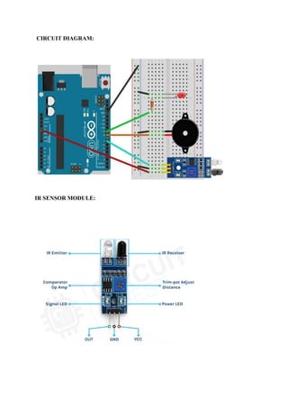
• Connect the circuit as shown in the circuit diagram
• Connect the Arduino UNO board to the laptop or PC using a USB A-M to USB B-M
convertor cable.
• Open Arduino IDE and click on tools →port to select the corresponding communication
port.
• Write the code and click on verify/compile to check the errors.
• To upload the code click on upload and wait for the response.
• Verify the results.
Result:
JNTUK UNIVERSITY COLLEGEOF ENGINEERING NARASARAOPET
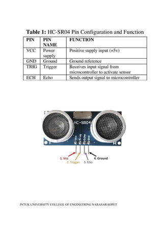
Exp No: Date:
INTERFACING ULTRASONIC SENSOR WITHARDUINO
AIM: To interface the ultrasonic sensor with Arduino UNO.
HARDWARE REQUIRED:
• Arduino UNO
• Ultrasonic sensor
• Resistor -1 (330 Ω)
• Connecting wires
• USB-A to B Cable
• Bread Board
• Jumper Wires
• LED
SOFTWARE REQUIRED:
• Arduino IDE
THEORY:
ULTRASONIC SENSOR:
• An ultrasonic sensor emits a sound pulse in the ultrasonic range. This sound pulse
propagates at the speed of sound through air (about 344 meters per second) until the
sound pulse encounters an object. The sound pulse bounces off the object and is
returned in reverse to the sensor where this "echo" is received. By measuring the time
it takes for the sound pulse to travel from sensor to object and back to the sensor. The
distance to the object can be calculated very accurately. This measuring principle is
also called "Time of Flight", or transit time measurement.
JNTUK UNIVERSITY COLLEGEOF ENGINEERING NARASARAOPET
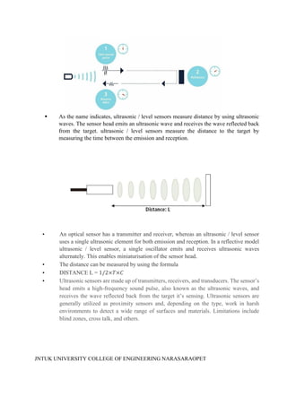
As the name indicates, ultrasonic / level sensors measure distance by using ultrasonic
waves. The sensor head emits an ultrasonic wave and receives the wave reflected back
from the target. ultrasonic / level sensors measure the distance to the target by
measuring the time between the emission and reception.
• An optical sensor has a transmitter and receiver, whereas an ultrasonic / level sensor
uses a single ultrasonic element for both emission and reception. In a reflective model
ultrasonic / level sensor, a single oscillator emits and receives ultrasonic waves
alternately. This enables miniaturisation of the sensor head.
• The distance can be measured by using the formula
• DISTANCE L = 1/2×𝑇×𝐶
• Ultrasonic sensors are made up of transmitters, receivers, and transducers. The sensor’s
head emits a high-frequency sound pulse, also known as the ultrasonic waves, and
receives the wave reflected back from the target it’s sensing. Ultrasonic sensors are
generally utilized as proximity sensors and, depending on the type, work in harsh
environments to detect a wide range of surfaces and materials. Limitations include
blind zones, cross talk, and others.
JNTUK UNIVERSITY COLLEGEOF ENGINEERING NARASARAOPET
ARDUINO UNO:
The Arduino Uno is a microcontroller board based on the ATmega328. It has 20 digital
input/output pins (of which 6 can be used as PWM outputs and 6 can be used as analog inputs),
a 16 MHz resonator, a USB connection, a power jack, an in-circuit system programming
(ICSP) header, and a reset button.
SOURCE CODE:
#define Trigpin 7
#define Echopin 8
#define high_led 10
float distance;
int duration;
int ll = 300;
void setup() {
pinMode (Trigpin, OUTPUT);
pinMode (high_led, OUTPUT);
pinMode (Echopin, INPUT);
Serial.begin(9600);
Serial.println ("Welcome To Distance Meter");
Serial.println ("Coded By Jevins Annson");
digitalWrite (high_led, LOW);
}
void loop() {
digitalWrite(Trigpin, LOW);
delayMicroseconds(2);
digitalWrite(Trigpin, HIGH);
delayMicroseconds(10);
digitalWrite(Trigpin, LOW);
duration = pulseIn(Echopin, HIGH);
distance = duration * 0.034 / 2;
delay (ll);
Serial.println (" ");
Serial.print ("Distance = ");
Serial.print (distance);
Serial.print (" CM");
Serial.println (" ");
if (distance>=30)
{
Serial.println ("Nobody Is Infront Of the Sensor");
JNTUK UNIVERSITY COLLEGEOF ENGINEERING NARASARAOPET
digitalWrite (led, LOW);
delay (500);
} else
{
Serial.println ("Someone Is Infront Of the Sensor");
digitalWrite (led, HIGH);
delay (100);
}
}
CODE DESCRIPTION:
• Define an integer type variable Trig pin and assign 6 to it. Then we define another
integer type variable Echo pin and assign 7 to it. Later we define another integer type
variable LED and assign 9 to it.
• Initialize Trigpin as an output.
• pinMode(Trigpin,OUTPUT)
• Initialize high_led as an output.
• pinMode(high_led,OUTPUT)
• Initialize Echopin as an input.
• pinMode(Echopin,INPUT)
• Then for serial communication we are setting a baud rate of 9600 by using the function
Serial.begin().
• In ‘if block’, if object is at a distance greater than 30 cm , it will print , a message on
the serial monitor “No body is infront of the sensor” & LED turns off , otherwise it will
print , a message on the serial monitor “Someone Is Infront Of the Sensor” &LED turns
on.
JNTUK UNIVERSITY COLLEGEOF ENGINEERING NARASARAOPET
PROCEDURE:
• Connect the circuit as shown in the circuit diagram
• Connect the Arduino board to the laptop or PC
• Open Arduino IDE and click on tools and then port to select the corresponding
communication port.
• Write the code and click on verify/compile to check the errors.
• To upload the code click on upload and wait for the response.
• Verify the results.
RESULT:
JNTUK UNIVERSITY COLLEGEOF ENGINEERING NARASARAOPET
Exp No: Date:
GENERATION OF PWM USING ARDUINO
AIM: To generate PWM output with Arduino UNO.
HARDWARE REQUIRED:
• Arduino UNO
• LED
• Resistor -1 (330 Ω)
• Connecting wires
• USB-A to B Cable
• Bread Board
SOFTWARE REQUIRED:
• Arduino IDE
THEORY:
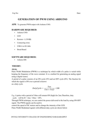
PWM:
Pulse Width Modulation (PWM) is a technique by which width of a pulse is varied while
keeping the frequency of the wave constant. It is a method for generating an analog signal
using a digital source.
A period of a pulse consists of an ON cycle (5V) and an OFF cycle (0V). The fraction for
which the signal is ON over a period is known
as a duty cycle.
E.g. A pulse with a period of 10ms will remain ON (high) for 2ms.Therefore, duty
cycle will be D = 2ms / 10ms = 20%
Through PWM technique, we can control the power delivered to the load by using ON-OFF
signal. The PWM signals can be used to
control the speed of DC motors and to change the intensity of the LED.
Pulse Width Modulated signals with different duty cycle are shown below
JNTUK UNIVERSITY COLLEGEOF ENGINEERING NARASARAOPET
Frequency of Signal
The frequency of a signal determines how fast the PWM completes a cycle (i.e. 1000 Hz
would be 1000 cycles per second) which
means how fast it switches between ON (high) and OFF (low) states. By repeating this ON-
OFF pattern at a fast-enough rate, and with a
certain duty cycle, the output will appear to behave like a constant voltage analog signal
when providing power to devices.
Example: If we want to create a 2V analog signal for a given digital source that can be
either high (on) at 5V, or low (off) at 0V, we can
use PWM with a duty cycle of 40%. It will provide output 5V for 40% of the time. If the
digital signal is cycled fast enough, then the
voltage seen at the output appears to be the average voltage. If the digital low is 0V (which
is usually the case) then the average
voltage can be calculated by taking the digital high voltage multiplied by the duty cycle, or
5V x 0.4 = 2V.
Now, let's see PWM in Arduino.
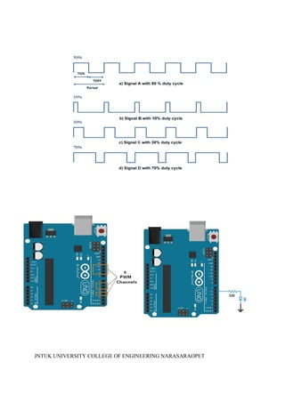
PWM Pins of Arduino Uno
Arduino Uno has 6 8-bit PWM channels. The pins with symbol ‘~’ represents that it has
PWM support. These PWM pins are shown in
below image.
Arduino Functions for PWM
analogWrite (pin, duty cycle)
It is used to generate PWM or output analog value to a specified PWM channel.
pin – pin on which we want to generate pwm or analog signal.
duty cycle – it lies in between 0 (0%, always off) – 255 (100%, always on).
e.g. analogWrite (3, 127) //generates pwm of 50% duty cycle
LED Fading using Arduino PWM
Let’s create small application in which led will fade continuously. This led fading
application used for decoration in functions and
festivals.
CODE:
int led = 6; // the PWM pin the LED is attached to
int brightness = 0; // how bright the LED is
int fadeAmount = 5; // how many points to fade the LED by
void setup() {
pinMode(led, OUTPUT); // declare pwm pin to be an output:
}
JNTUK UNIVERSITY COLLEGEOF ENGINEERING NARASARAOPET
void loop() {
analogWrite(led, brightness); // set the brightness of led
// change the brightness for next time through the loop:
brightness = brightness + fadeAmount;
// reverse the direction of the fading at the ends of the fade:
if (brightness <= 0 || brightness >= 255) {
fadeAmount = -fadeAmount;
}
delay(30); // wait for 30 milliseconds to see the dimming effect
}
PROCEDURE:
• Connect the circuit as shown in the circuit diagram.
• Connect the Arduino board to the laptop or PC.
• Open Arduino IDE and click on tools and then port to select the corresponding
communication port.
• Write the code and click on verify/compile to check the errors.
• To upload the code, click on upload and wait for the response.
• Verify the results.
RESULT: