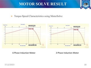
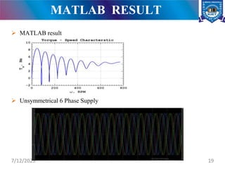
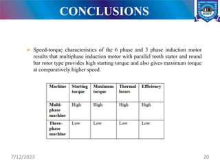
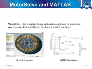
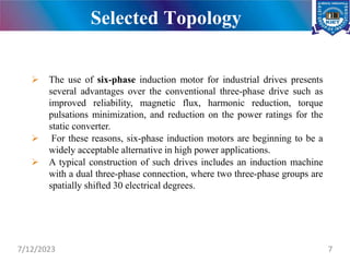
ANALYSIS AND DESIGN OF MULTIPHASE INDUCTION
MACHINE
A
Project Power Point Presentation
(Submitted in partial fulfilment of the requirements for the degree
of
BACHELOR OFTECHNOLOGY
in
ELCECTRICAL & ELECTRONICS ENGINEERING
ELECTRICAL & ELECTRONICS ENGINEERING DEPARTMENT
KIET GROUP OF INSTITUTIONS, GHAZIABAD
Dr. A. P. J. ABDUL KALAM TECHNICAL UNIVERSITY, UTTAR PRADESH,
LUCKNOW
SUBMITTED BY:
GROUP NO.: 55
Shivangi Mishra
Somu Gupta
Yash Bindal
GUIDE:
Dr. Ramesh Singh
(Asst. Professor)
EEE Department
KIET GROUP OF INSTITUTIONS, GHAZIABAD
APRIL, 2020
CONTENTS
• Introduction
• Literature Review
• Objective Function
• Methodology
• Software Setup
• Details and specification of equipment’s used in calibration,
measurement and data collection
• Testing, Data Collection & Analysis
• Results and Conclusions
• Conclusions and Future Scope
• Publications
• References
7/12/2023 2
INTRODUCTION
 Induction motor are also called AC electric motor and the rotating torque in the
rotor is obtained due to electromagnetic induction in the rotating magnetic field of
the stator winding. As they operate at speed less than synchronous speed these
motor are also referred as asynchronous motor
THREE PHASE INDUCTION MOTOR:-
It consists of a stator with stator windings and a rotor. The stator carries a 3-phase
winding while the rotor carries a short circuited rotor winding. When the three-phase
voltages are applied to the stator windings, a rotating magnetic field is established. As
the magnetic field rotates, currents are induced in the conductors of the squirrel cage
rotor. The interaction of the induced currents and the magnetic field produces forces
that cause the rotor to rotate.
MULTIPHASE INDUCTION MOTOR:-
Stator carries more than 3 phase stator winding, working principle will be same as that
of three phase induction machine but phases will be divided into number of groups.
7/12/2023 3
LITERATURE REVIEW
7/12/2023 4
Sr. No. Author Name Journal Title
1 Mayukh Bose,
Anshuman
Bhatacharjee, & Sudha
R.
International Journal of
Soft Computing and
Engineering (ISCE), Vol.
2(3), July 2012.
Calculation of Induction
Motor Model
Parameters Using Finite
Element Method
2 D. Novotony, and T.A.
Lipo
Clarendon Press,
Oxford, UK, 2000.
Vector control and
dynamics of ac drives
3 Hassan M. Emara,
Wesam Elshamy & A.
Bahgat
Particle Swarm
Optimization Algorithm.
Journal
Parameter Identification
of Induction Motor
Using Modified Particle
Swarm Optimization
Algorithm
4 R. Lyra and T. A. Lipo
IEEE Trans. Ind. Appl.
Vol. 38, no. 5, pp. 1351-
1360, Sept./Oct. 2002
Torque density
improvement in a six-
phase induction motor
with third harmonic
current injection
5 Levi, R. Bojoi, F.
Profumo, H. A. Toliyat
and S. Williamson
IET Electric Power
Applications, vol. 1, no.
4, pp. 489-516, July
2007.
Multiphaseinduction
motor drives - a
technology status
review
6 B. Robyns Journal of Power
Systems, DOI(2012)
Vector Control of
Induction Machines
OBJECTIVE FUNCTION
The objective of the proposed project is to obtain
 Lower torque pulsation.
 Reduction in harmonic currents.
 To obtain reduced current per phase without the need to increase the phase
voltage, greater reliability.
 Fault tolerant feature.
 Increased power to weight ratio and higher reliability.
 Can be operate normally when one or several phases fail.
 By increasing the phase number, low-speed operation performance can be
improved.
7/12/2023 5
MotorSolve and MATLAB
Model
7/12/2023 6
• MotorSolve is the complete design and analysis software for induction,
synchronous, electronically and brush-commutated machines.
MotorSolve model MATAB Simulation
Selected Topology
7/12/2023 7
 The use of six-phase induction motor for industrial drives presents
several advantages over the conventional three-phase drive such as
improved reliability, magnetic flux, harmonic reduction, torque
pulsations minimization, and reduction on the power ratings for the
static converter.
 For these reasons, six-phase induction motors are beginning to be a
widely acceptable alternative in high power applications.
 A typical construction of such drives includes an induction machine
with a dual three-phase connection, where two three-phase groups are
spatially shifted 30 electrical degrees.
Design of Six Phase IM
Induction motor design starts from stator design. Stator design depends
upon number stator slots.
General expression for number of stator slots is given by, S= n/2.p.[2+K]
Where S = no. of slots
n = no. of machine phases
p = no. of machine poles
For symmetrical ac winding: K = 0, 2, 4
For Asymmetrical ac winding: K = 1, 3, 5
In our case, number of poles = 6
7/12/2023 8
The two, three phase windings are displaced by 60 degrees in symmetrical
design, but there is a problem of magnetic circulating currents. So
asymmetrical design is implemented in which two three phase windings are
displaced by 30 degrees, which eliminates 6n±1 order harmonics.
θm = 2. θe / p
θm = 2 . 30° / 4 = 15° mechanical
Slot pitch = 360° / 36 = 10° mechanical
7/12/2023 9
Mathematical Transformation
• Analysis of three or more phase is done by transformation of variables in
different frame.
abc  dq
• Clark transformation (abc to )
• Park transformation ( to dq)
7/12/2023 10
d-q Equation for Multiphase Induction Motor
• In the case of balanced three phase circuits, application of d-q transformation reduces
the three AC quantities to 2 quantities. Simplified calculations can then be carried out
on these imaginary quantities.
• Transformation can be applied for both phase current and phase voltage.
Stator circuit equation
𝑉𝑑𝑠 = 𝑅𝑠𝐼𝑑𝑠 +
𝑑𝑑𝑠
𝑑𝑡
− 𝑊𝑒𝑞𝑠
𝑉𝑞𝑠 = 𝑅𝑠𝐼𝑞𝑠 +
𝑑𝑞𝑠
𝑑𝑡
+ 𝑊𝑒𝑑𝑠
Rotor circuit equation
𝑉𝑑𝑟 = 𝑅𝑟𝐼𝑑𝑟 +
𝑑𝑑𝑟
𝑑𝑡
− (𝑊𝑒 − 𝑊𝑟)𝑞𝑟
𝑉𝑞𝑟 = 𝑅𝑟𝐼𝑞𝑟 +
𝑑𝑞𝑟
𝑑𝑡
+ 𝑊𝑒 − 𝑊𝑟 𝑑𝑟
7/12/2023 11
Equation cont..
• Flux link
𝑑𝑠 = 𝐿𝑠𝐼𝑑𝑠 + 𝐿𝑚(𝐼𝑑𝑠 + 𝐼𝑑𝑟)
𝑑𝑟 = 𝐿𝑟𝐼𝑑𝑟 + 𝐿𝑚(𝐼𝑑𝑠 + 𝐼𝑑𝑟)
𝑞𝑠 = 𝐿𝑠𝐼𝑑𝑠 + 𝐿𝑚(𝐼𝑞𝑠 + 𝐼𝑞𝑟)
𝑞𝑟 = 𝐿𝑟𝐼𝑑𝑟 + 𝐿𝑚 𝐼𝑞𝑠 + 𝐼𝑞𝑟
𝑑𝑚 = 𝐿𝑚(𝐼𝑑𝑠 + 𝐼𝑑𝑟)
𝑞𝑚 = 𝐿𝑚(𝐼𝑞𝑠 + 𝐼𝑑𝑟)
• From above equations we get
𝐼𝑑𝑠 =
𝑑𝑠 𝐿𝑟 + 𝐿𝑚 − 𝐿𝑚𝑑𝑟
𝐿𝑠𝐿𝑟 + 𝐿𝑠𝐿𝑚 + 𝐿𝑟𝐿𝑚
𝐼𝑞𝑠 =
𝑞𝑠 𝐿𝑟 + 𝐿𝑚 − 𝐿𝑚𝑞𝑟
𝐿𝑠𝐿𝑟 + 𝐿𝑠𝐿𝑚 + 𝐿𝑟𝐿𝑚
7/12/2023 12
Equation cont..
𝐼𝑑𝑟 =
𝑑𝑟 𝐿𝑠 + 𝐿𝑚 − 𝐿𝑚𝑑𝑠
𝐿𝑠𝐿𝑟 + 𝐿𝑠𝐿𝑚 + 𝐿𝑟𝐿𝑚
𝐼𝑞𝑟 =
𝑞𝑟 𝐿𝑠 + 𝐿𝑚 − 𝐿𝑚𝑞𝑠
𝐿𝑠𝐿𝑟 + 𝐿𝑠𝐿𝑚 + 𝐿𝑟𝐿𝑚
Where Lm= (N/2) M
M= Maximum value of stator to rotor mutual inductance
𝑇𝑒 = 𝑃𝐿𝑚(𝐼𝑞𝑠𝐼𝑑𝑟 − 𝐼𝑑𝑠𝐼𝑞𝑟)
7/12/2023 13
Machine Dimensions and Ratings
• Voltage: 415V
• Phase: 6
• Frequency: 50Hz
• No. of Poles: 6
• Rotor slip: 5
• Synchronous speed: 1000rpm
• Power Rating: 4.92 HP
• No. of Phase Group: 2
• Air gap thickness: 0.5
• Motor aspect ratio: 0.9
• R1: 0.782
• R2: 3.95
• L1: 11.4 H
• L2: 19.5 H
7/12/2023 14
MotorSolve Stator Winding and Motor View
7/12/2023 15
Stator winding Motor view
Rotating Magnetic Field
7/12/2023 16
MATLAB Simulink Model
7/12/2023 17
MOTOR SOLVE RESULT
7/12/2023 18
 Torque-Speed Characteristics using MotorSolve
6 Phase Induction Motor 3 Phase Induction Motor
MATLAB RESULT
 MATLAB result
 Unsymmetrical 6 Phase Supply
7/12/2023 19
CONCLUSIONS
7/12/2023 20
 Speed-torque characteristics of the 6 phase and 3 phase induction motor
results that multiphase induction motor with parallel tooth stator and round
bar rotor type provides high starting torque and also gives maximum torque
at comparatively higher speed.
FUTURE SCOPE
7/12/2023 21
 Electric propulsion systems in electric and hybrid vehicles
 Aerospace
 Military equipment
 Electrical Vehicles
The Project can be extended by applying for funding to different schemes as:
1. Council of Science and Technology – Uttar Pradesh (CSTUP)
2. Kalam Annual Project and Poster Technical Competition (KAPPTeC)
3. Department of Science and Technology (DST)
4. Nidhi Prayas Yojna (NPY)
5. Nidhi EIR Yojna (NEIRY)
6. All India Council of Technical Education (AICTE)
7. Institute of Electrical and Electronics Engineering Grants (IEEE)
8. Institute of Electrical and Electronics Engineering Special Interest Group on
Humanitarian Technology (IEEE – SIGHT)
9. Ministry of Electronics and Technology (MIETY)
7/12/2023 22
GRANTS AND GOVERNMENT SCHEMES IN WHICH PROJECT
CAN BE APPLIED FOR FUTURE
PUBLICATION
7/12/2023 23
 Effect of Stator Slot in the Performance of Multiphase Induction Motor
(IEEE conference –CIPECH 2020)
 Comparative Study of Multiphase and Three Phase Induction Motor
(To be communicated in SCOPUS/SCI journal)
REFERENCES
• IEEE TRANSACTIONS ON INDUSTRIAL ELECTRONICS – DOI: 10.1109/TIE.2015.2447733. Recent Advances
in the Design, Modeling and Control of Multiphase Machines – Part 1. Federico Barrero, Senior Member, IEEE,
Mario J. Duran.
• H. Xu, H.A. Toliyat and L.J. Peterson, “Five-phase induction motor with DSP based control system”, IEEE Trans.
Power Elect., vol. 17, no. 4, pp. 524-533, Jul. 2002.
• 2011 IEEE International Electric Machines & Drives Conference (IEMDC). Design and Control of Multiphase
Induction Motor.. By Archana Nanoty, Student Member, IEEE, A.R. Chudasama. Emil Levi, “Recent Developments
in High Performance Variable-Speed Multiphase Induction Motor Drives” sixth international symposium nikola tesla
October 18 – 20, 2006, Belgrade, SASA, Serbia.
• R. Lyra and T. A. Lipo, “Torque density improvement in a sixphase induction motor with third harmonic current
injection”, IEEE Trans. Ind. Appl. Vol. 38, no. 5, pp. 1351-1360, Sept./Oct. 2002.
Y. Zhao, and T. A. Lipo, “Modeling and control of a Multi-phase induction machine with structural unbalance. Part I:
Machine modeling and multi-dimensional current regulation,” IEEE Trans. Energy Conver., vol. 11, no. 3, pp. 570-
577, Sep. 1996.
• R. Bojoi, M. Lazzari, F. Profumo, and A. Tenconi, “Digital field-oriented control of dual three-phase induction motor
drives,” IEEE Trans. Ind. Appl., vol. 39, no. 3, pp. 752-760, May 2003.
• World Academy of Science, Engineering and Technology International Journal of Electrical, Computer, Energetic,
Electronic and Communication Engineering Vol:6, No:9, 2012. Generalized d-q Model of n-Phase Induction Motor
Drive, By G. Renukadevi, K. Rajambal.
• Analysis of multi-phase induction machines with winding faults J.M. Apsley and S. Williamson University of
Manchester, School of Electrical and Electronic Engineering P.O. Box 88, Sackville Street Manchester, M60 1QD,
United Kingdom.
• L. Romeral,Departament d’Enginyeria Electrònica. Universitat Politécnica de Catalunya “Motion Control for Electric
Drives”.
7/12/2023 24
References cont…
• G. K. Singh, and V. Pant, “Analysis of a multi-phase induction machine under fault condition in a phase-
redundant AC drive system,” Elect. Mach. Power Sys., vol. 28, no. 6, pp.577-590, Nov. 2010.
• N. Tleis, Power System Modelling and Fault Analysis. Amsterdam: Elsevier Ltd., 2008.
• T. A. Lipo, Analysis of Synchronous Machines. 2nd edition, New York: CRC Press, 2012.
• P. L. Alger, Induction Machines. New York: Gorden and Breach, 1970.
• M. R. Aghamohammadi, M. Pourgholi, “Experience with SSSFR test for synchronous generator model
identification using Hook-Jeeves optimization method,” Int. J Sys. Appl., Eng& Develop, vol.2, no.3, pp. 122-127,
2008.
• Mayukh Bose, Anshuman Bhatacharjee, & Sudha R. (2012), Calculation of Induction Motor Model Parameters
Using Finite Element Method. International Journal of Soft Computing and Engineering (ISCE), Vol. 2(3), July
2012.
• D. Novotony, and T.A. Lipo, Vector control and dynamics of ac drives, Clarendon Press, Oxford, UK, 2000.
• C. V. Jones, The Unified Theory of Electric Machine. London: Butterworths, 1967.
• R. Bojoi, F. Farina, M. Lazzari, F. Profumo, and A. Tenconi, “Analysis of the asymmetrical operation of dual
three-phase induction machines,” Proc. IEMDC, Madsion, WI, pp. 429-435, 2003.
• Journal articles: -
David, A.B., Pandit, M.M. and Sinha, B.K., "Measurement of surface viscosity by tensiometric methods", Chem.
Engng Sci., Vol. 47 (2), 2005, pp. 931-945.
• Book: -
Doraiswamy, L.K. and Sharma, M.M., "Heterogeneous Reactions- Vol 1", Wiley, New York, 1984, pp. 89-90.
• MyLOFT app or website link- https://app.myloft.xyz/user/login?institute=ck4o420t2s5ya099816x5aby9.
7/12/2023 25
7/12/2023 26
 Project group members are encouraged to insert a slogan with their
supervisors at the end presentation on COVID-19.
THANK
7/12/2023 27
Stay Safe, Stay at Home

ANALYSIS AND DESIGN OF MULTIPHASE INDUCTION MACHINE.pptx

  • 1.
    ANALYSIS AND DESIGNOF MULTIPHASE INDUCTION MACHINE A Project Power Point Presentation (Submitted in partial fulfilment of the requirements for the degree of BACHELOR OFTECHNOLOGY in ELCECTRICAL & ELECTRONICS ENGINEERING ELECTRICAL & ELECTRONICS ENGINEERING DEPARTMENT KIET GROUP OF INSTITUTIONS, GHAZIABAD Dr. A. P. J. ABDUL KALAM TECHNICAL UNIVERSITY, UTTAR PRADESH, LUCKNOW SUBMITTED BY: GROUP NO.: 55 Shivangi Mishra Somu Gupta Yash Bindal GUIDE: Dr. Ramesh Singh (Asst. Professor) EEE Department KIET GROUP OF INSTITUTIONS, GHAZIABAD APRIL, 2020
  • 2.
    CONTENTS • Introduction • LiteratureReview • Objective Function • Methodology • Software Setup • Details and specification of equipment’s used in calibration, measurement and data collection • Testing, Data Collection & Analysis • Results and Conclusions • Conclusions and Future Scope • Publications • References 7/12/2023 2
  • 3.
    INTRODUCTION  Induction motorare also called AC electric motor and the rotating torque in the rotor is obtained due to electromagnetic induction in the rotating magnetic field of the stator winding. As they operate at speed less than synchronous speed these motor are also referred as asynchronous motor THREE PHASE INDUCTION MOTOR:- It consists of a stator with stator windings and a rotor. The stator carries a 3-phase winding while the rotor carries a short circuited rotor winding. When the three-phase voltages are applied to the stator windings, a rotating magnetic field is established. As the magnetic field rotates, currents are induced in the conductors of the squirrel cage rotor. The interaction of the induced currents and the magnetic field produces forces that cause the rotor to rotate. MULTIPHASE INDUCTION MOTOR:- Stator carries more than 3 phase stator winding, working principle will be same as that of three phase induction machine but phases will be divided into number of groups. 7/12/2023 3
  • 4.
    LITERATURE REVIEW 7/12/2023 4 Sr.No. Author Name Journal Title 1 Mayukh Bose, Anshuman Bhatacharjee, & Sudha R. International Journal of Soft Computing and Engineering (ISCE), Vol. 2(3), July 2012. Calculation of Induction Motor Model Parameters Using Finite Element Method 2 D. Novotony, and T.A. Lipo Clarendon Press, Oxford, UK, 2000. Vector control and dynamics of ac drives 3 Hassan M. Emara, Wesam Elshamy & A. Bahgat Particle Swarm Optimization Algorithm. Journal Parameter Identification of Induction Motor Using Modified Particle Swarm Optimization Algorithm 4 R. Lyra and T. A. Lipo IEEE Trans. Ind. Appl. Vol. 38, no. 5, pp. 1351- 1360, Sept./Oct. 2002 Torque density improvement in a six- phase induction motor with third harmonic current injection 5 Levi, R. Bojoi, F. Profumo, H. A. Toliyat and S. Williamson IET Electric Power Applications, vol. 1, no. 4, pp. 489-516, July 2007. Multiphaseinduction motor drives - a technology status review 6 B. Robyns Journal of Power Systems, DOI(2012) Vector Control of Induction Machines
  • 5.
    OBJECTIVE FUNCTION The objectiveof the proposed project is to obtain  Lower torque pulsation.  Reduction in harmonic currents.  To obtain reduced current per phase without the need to increase the phase voltage, greater reliability.  Fault tolerant feature.  Increased power to weight ratio and higher reliability.  Can be operate normally when one or several phases fail.  By increasing the phase number, low-speed operation performance can be improved. 7/12/2023 5
  • 6.
    MotorSolve and MATLAB Model 7/12/20236 • MotorSolve is the complete design and analysis software for induction, synchronous, electronically and brush-commutated machines. MotorSolve model MATAB Simulation
  • 7.
    Selected Topology 7/12/2023 7 The use of six-phase induction motor for industrial drives presents several advantages over the conventional three-phase drive such as improved reliability, magnetic flux, harmonic reduction, torque pulsations minimization, and reduction on the power ratings for the static converter.  For these reasons, six-phase induction motors are beginning to be a widely acceptable alternative in high power applications.  A typical construction of such drives includes an induction machine with a dual three-phase connection, where two three-phase groups are spatially shifted 30 electrical degrees.
  • 8.
    Design of SixPhase IM Induction motor design starts from stator design. Stator design depends upon number stator slots. General expression for number of stator slots is given by, S= n/2.p.[2+K] Where S = no. of slots n = no. of machine phases p = no. of machine poles For symmetrical ac winding: K = 0, 2, 4 For Asymmetrical ac winding: K = 1, 3, 5 In our case, number of poles = 6 7/12/2023 8
  • 9.
    The two, threephase windings are displaced by 60 degrees in symmetrical design, but there is a problem of magnetic circulating currents. So asymmetrical design is implemented in which two three phase windings are displaced by 30 degrees, which eliminates 6n±1 order harmonics. θm = 2. θe / p θm = 2 . 30° / 4 = 15° mechanical Slot pitch = 360° / 36 = 10° mechanical 7/12/2023 9
  • 10.
    Mathematical Transformation • Analysisof three or more phase is done by transformation of variables in different frame. abc  dq • Clark transformation (abc to ) • Park transformation ( to dq) 7/12/2023 10
  • 11.
    d-q Equation forMultiphase Induction Motor • In the case of balanced three phase circuits, application of d-q transformation reduces the three AC quantities to 2 quantities. Simplified calculations can then be carried out on these imaginary quantities. • Transformation can be applied for both phase current and phase voltage. Stator circuit equation 𝑉𝑑𝑠 = 𝑅𝑠𝐼𝑑𝑠 + 𝑑𝑑𝑠 𝑑𝑡 − 𝑊𝑒𝑞𝑠 𝑉𝑞𝑠 = 𝑅𝑠𝐼𝑞𝑠 + 𝑑𝑞𝑠 𝑑𝑡 + 𝑊𝑒𝑑𝑠 Rotor circuit equation 𝑉𝑑𝑟 = 𝑅𝑟𝐼𝑑𝑟 + 𝑑𝑑𝑟 𝑑𝑡 − (𝑊𝑒 − 𝑊𝑟)𝑞𝑟 𝑉𝑞𝑟 = 𝑅𝑟𝐼𝑞𝑟 + 𝑑𝑞𝑟 𝑑𝑡 + 𝑊𝑒 − 𝑊𝑟 𝑑𝑟 7/12/2023 11
  • 12.
    Equation cont.. • Fluxlink 𝑑𝑠 = 𝐿𝑠𝐼𝑑𝑠 + 𝐿𝑚(𝐼𝑑𝑠 + 𝐼𝑑𝑟) 𝑑𝑟 = 𝐿𝑟𝐼𝑑𝑟 + 𝐿𝑚(𝐼𝑑𝑠 + 𝐼𝑑𝑟) 𝑞𝑠 = 𝐿𝑠𝐼𝑑𝑠 + 𝐿𝑚(𝐼𝑞𝑠 + 𝐼𝑞𝑟) 𝑞𝑟 = 𝐿𝑟𝐼𝑑𝑟 + 𝐿𝑚 𝐼𝑞𝑠 + 𝐼𝑞𝑟 𝑑𝑚 = 𝐿𝑚(𝐼𝑑𝑠 + 𝐼𝑑𝑟) 𝑞𝑚 = 𝐿𝑚(𝐼𝑞𝑠 + 𝐼𝑑𝑟) • From above equations we get 𝐼𝑑𝑠 = 𝑑𝑠 𝐿𝑟 + 𝐿𝑚 − 𝐿𝑚𝑑𝑟 𝐿𝑠𝐿𝑟 + 𝐿𝑠𝐿𝑚 + 𝐿𝑟𝐿𝑚 𝐼𝑞𝑠 = 𝑞𝑠 𝐿𝑟 + 𝐿𝑚 − 𝐿𝑚𝑞𝑟 𝐿𝑠𝐿𝑟 + 𝐿𝑠𝐿𝑚 + 𝐿𝑟𝐿𝑚 7/12/2023 12
  • 13.
    Equation cont.. 𝐼𝑑𝑟 = 𝑑𝑟𝐿𝑠 + 𝐿𝑚 − 𝐿𝑚𝑑𝑠 𝐿𝑠𝐿𝑟 + 𝐿𝑠𝐿𝑚 + 𝐿𝑟𝐿𝑚 𝐼𝑞𝑟 = 𝑞𝑟 𝐿𝑠 + 𝐿𝑚 − 𝐿𝑚𝑞𝑠 𝐿𝑠𝐿𝑟 + 𝐿𝑠𝐿𝑚 + 𝐿𝑟𝐿𝑚 Where Lm= (N/2) M M= Maximum value of stator to rotor mutual inductance 𝑇𝑒 = 𝑃𝐿𝑚(𝐼𝑞𝑠𝐼𝑑𝑟 − 𝐼𝑑𝑠𝐼𝑞𝑟) 7/12/2023 13
  • 14.
    Machine Dimensions andRatings • Voltage: 415V • Phase: 6 • Frequency: 50Hz • No. of Poles: 6 • Rotor slip: 5 • Synchronous speed: 1000rpm • Power Rating: 4.92 HP • No. of Phase Group: 2 • Air gap thickness: 0.5 • Motor aspect ratio: 0.9 • R1: 0.782 • R2: 3.95 • L1: 11.4 H • L2: 19.5 H 7/12/2023 14
  • 15.
    MotorSolve Stator Windingand Motor View 7/12/2023 15 Stator winding Motor view
  • 16.
  • 17.
  • 18.
    MOTOR SOLVE RESULT 7/12/202318  Torque-Speed Characteristics using MotorSolve 6 Phase Induction Motor 3 Phase Induction Motor
  • 19.
    MATLAB RESULT  MATLABresult  Unsymmetrical 6 Phase Supply 7/12/2023 19
  • 20.
    CONCLUSIONS 7/12/2023 20  Speed-torquecharacteristics of the 6 phase and 3 phase induction motor results that multiphase induction motor with parallel tooth stator and round bar rotor type provides high starting torque and also gives maximum torque at comparatively higher speed.
  • 21.
    FUTURE SCOPE 7/12/2023 21 Electric propulsion systems in electric and hybrid vehicles  Aerospace  Military equipment  Electrical Vehicles
  • 22.
    The Project canbe extended by applying for funding to different schemes as: 1. Council of Science and Technology – Uttar Pradesh (CSTUP) 2. Kalam Annual Project and Poster Technical Competition (KAPPTeC) 3. Department of Science and Technology (DST) 4. Nidhi Prayas Yojna (NPY) 5. Nidhi EIR Yojna (NEIRY) 6. All India Council of Technical Education (AICTE) 7. Institute of Electrical and Electronics Engineering Grants (IEEE) 8. Institute of Electrical and Electronics Engineering Special Interest Group on Humanitarian Technology (IEEE – SIGHT) 9. Ministry of Electronics and Technology (MIETY) 7/12/2023 22 GRANTS AND GOVERNMENT SCHEMES IN WHICH PROJECT CAN BE APPLIED FOR FUTURE
  • 23.
    PUBLICATION 7/12/2023 23  Effectof Stator Slot in the Performance of Multiphase Induction Motor (IEEE conference –CIPECH 2020)  Comparative Study of Multiphase and Three Phase Induction Motor (To be communicated in SCOPUS/SCI journal)
  • 24.
    REFERENCES • IEEE TRANSACTIONSON INDUSTRIAL ELECTRONICS – DOI: 10.1109/TIE.2015.2447733. Recent Advances in the Design, Modeling and Control of Multiphase Machines – Part 1. Federico Barrero, Senior Member, IEEE, Mario J. Duran. • H. Xu, H.A. Toliyat and L.J. Peterson, “Five-phase induction motor with DSP based control system”, IEEE Trans. Power Elect., vol. 17, no. 4, pp. 524-533, Jul. 2002. • 2011 IEEE International Electric Machines & Drives Conference (IEMDC). Design and Control of Multiphase Induction Motor.. By Archana Nanoty, Student Member, IEEE, A.R. Chudasama. Emil Levi, “Recent Developments in High Performance Variable-Speed Multiphase Induction Motor Drives” sixth international symposium nikola tesla October 18 – 20, 2006, Belgrade, SASA, Serbia. • R. Lyra and T. A. Lipo, “Torque density improvement in a sixphase induction motor with third harmonic current injection”, IEEE Trans. Ind. Appl. Vol. 38, no. 5, pp. 1351-1360, Sept./Oct. 2002. Y. Zhao, and T. A. Lipo, “Modeling and control of a Multi-phase induction machine with structural unbalance. Part I: Machine modeling and multi-dimensional current regulation,” IEEE Trans. Energy Conver., vol. 11, no. 3, pp. 570- 577, Sep. 1996. • R. Bojoi, M. Lazzari, F. Profumo, and A. Tenconi, “Digital field-oriented control of dual three-phase induction motor drives,” IEEE Trans. Ind. Appl., vol. 39, no. 3, pp. 752-760, May 2003. • World Academy of Science, Engineering and Technology International Journal of Electrical, Computer, Energetic, Electronic and Communication Engineering Vol:6, No:9, 2012. Generalized d-q Model of n-Phase Induction Motor Drive, By G. Renukadevi, K. Rajambal. • Analysis of multi-phase induction machines with winding faults J.M. Apsley and S. Williamson University of Manchester, School of Electrical and Electronic Engineering P.O. Box 88, Sackville Street Manchester, M60 1QD, United Kingdom. • L. Romeral,Departament d’Enginyeria Electrònica. Universitat Politécnica de Catalunya “Motion Control for Electric Drives”. 7/12/2023 24
  • 25.
    References cont… • G.K. Singh, and V. Pant, “Analysis of a multi-phase induction machine under fault condition in a phase- redundant AC drive system,” Elect. Mach. Power Sys., vol. 28, no. 6, pp.577-590, Nov. 2010. • N. Tleis, Power System Modelling and Fault Analysis. Amsterdam: Elsevier Ltd., 2008. • T. A. Lipo, Analysis of Synchronous Machines. 2nd edition, New York: CRC Press, 2012. • P. L. Alger, Induction Machines. New York: Gorden and Breach, 1970. • M. R. Aghamohammadi, M. Pourgholi, “Experience with SSSFR test for synchronous generator model identification using Hook-Jeeves optimization method,” Int. J Sys. Appl., Eng& Develop, vol.2, no.3, pp. 122-127, 2008. • Mayukh Bose, Anshuman Bhatacharjee, & Sudha R. (2012), Calculation of Induction Motor Model Parameters Using Finite Element Method. International Journal of Soft Computing and Engineering (ISCE), Vol. 2(3), July 2012. • D. Novotony, and T.A. Lipo, Vector control and dynamics of ac drives, Clarendon Press, Oxford, UK, 2000. • C. V. Jones, The Unified Theory of Electric Machine. London: Butterworths, 1967. • R. Bojoi, F. Farina, M. Lazzari, F. Profumo, and A. Tenconi, “Analysis of the asymmetrical operation of dual three-phase induction machines,” Proc. IEMDC, Madsion, WI, pp. 429-435, 2003. • Journal articles: - David, A.B., Pandit, M.M. and Sinha, B.K., "Measurement of surface viscosity by tensiometric methods", Chem. Engng Sci., Vol. 47 (2), 2005, pp. 931-945. • Book: - Doraiswamy, L.K. and Sharma, M.M., "Heterogeneous Reactions- Vol 1", Wiley, New York, 1984, pp. 89-90. • MyLOFT app or website link- https://app.myloft.xyz/user/login?institute=ck4o420t2s5ya099816x5aby9. 7/12/2023 25
  • 26.
    7/12/2023 26  Projectgroup members are encouraged to insert a slogan with their supervisors at the end presentation on COVID-19.
  • 27.