Downloaded 147 times


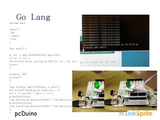
![C Command line
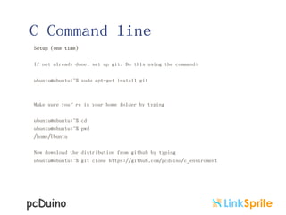
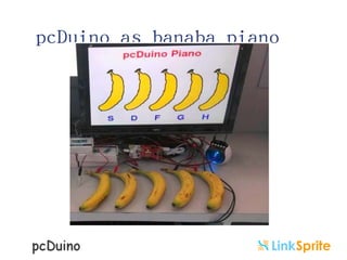
Change into the c_enviroment folder:
ubuntu@ubuntu:~$ cd c_enviroment
ubuntu@ubuntu:~/c_enviroment$ ls
Makefile hardware libraries output sample
Now run make to make the libraries and the examples with the following command:
ubuntu@ubuntu:~/c_enviroment$ make
Make[1]: Leaving directory `/home/ubuntu/c_enviroment/sample'
The resulting binary files are found in the output/test folder
ubuntu@ubuntu:~/c_enviroment$ cd output/test
ubuntu@ubuntu:~/c_enviroment/output/test$ ll
total 660
drwxrwxr-x 2 ubuntu ubuntu 4096 Apr 27 06:59 ./
drwxrwxr-x 3 ubuntu ubuntu 4096 Apr 27 06:49 ../
-rwxrwxr-x 1 ubuntu ubuntu 13868 Apr 27 06:58 adc_test*
-rwxrwxr-x 1 ubuntu ubuntu 28284 Apr 27 06:58 adxl345_test*
-rwxrwxr-x 1 ubuntu ubuntu 14209 Apr 27 06:58 interrupt_test*
-rwxrwxr-x 1 ubuntu ubuntu 13726 Apr 27 06:58 io_test*
-rwxrwxr-x 1 ubuntu ubuntu 13712 Apr 27 06:59 linker_button_test*
-rwxrwxr-x 1 ubuntu ubuntu 13907 Apr 27 06:59 linker_buzzer_test*
-rwxrwxr-x 1 ubuntu ubuntu 13689 Apr 27 06:59 linker_hall_sensor_test*
-rwxrwxr-x 1 ubuntu ubuntu 13760 Apr 27 06:59 linker_joystick_test*
-rwxrwxr-x 1 ubuntu ubuntu 13769 Apr 27 06:59 linker_led_bar_test*
-rwxrwxr-x 1 ubuntu ubuntu 13690 Apr 27 06:59 linker_led_test*
-rwxrwxr-x 1 ubuntu ubuntu 14290 Apr 27 06:59 linker_light_sensor_test*
““](https://image.slidesharecdn.com/pcduinosharc-140210105006-phpapp02/85/Introduction-to-pcDuino-12-320.jpg)
![C Command line
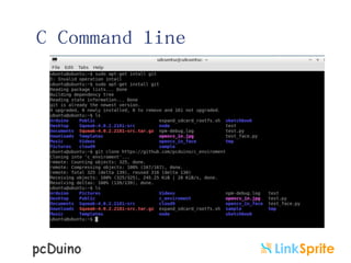
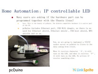
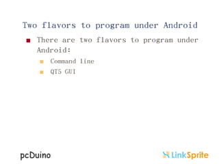
To view the contents of a sample sketch, (this
example we’ll look at the contents of
linker_led_test.c) type:
ubuntu@ubuntu:~/c_enviroment/sample$ cat
linker_led_test.c
/*
* LED test program
*/
#include <core.h>
int led_pin = 1;
void setup()
{
if(argc != 2){
goto _help;
}
led_pin = atoi(argv[1]);
if((led_pin < 0) || (led_pin > 13)){
goto _help;
}
pinMode(led_pin, OUTPUT);
return;
_help:
printf("Usage %s LED_PIN_NUM(0-13)n", argv[0]);
exit(-1);
}
void loop()
{
digitalWrite(led_pin, HIGH); // set the LED
on
delay(1000); // wait for a second
digitalWrite(led_pin, LOW); // set the LED
off
delay(1000); // wait for a second
}](https://image.slidesharecdn.com/pcduinosharc-140210105006-phpapp02/85/Introduction-to-pcDuino-13-320.jpg)


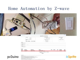
![OpenCV
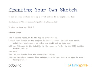
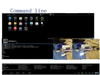
def process(infile):
image = cv.LoadImage(infile);
if image:
faces = detect_object(image)
im = Image.open(infile)
path = os.path.abspath(infile)
save_path = os.path.splitext(path)[0]+"_face"
try:
os.mkdir(save_path)
except:
pass
if faces:
draw = ImageDraw.Draw(im)
count = 0
for f in faces:
count += 1
draw.rectangle(f, outline=(255, 0, 0))
a = im.crop(f)
file_name =
os.path.join(save_path,str(count)+".jpg")
#
print file_name
a.save(file_name)
drow_save_path =
os.path.join(save_path,"out.jpg")
im.save(drow_save_path, "JPEG", quality=80)
else:
print "Error: cannot detect faces on %s" %
infile
if __name__ == "__main__":
process("./opencv_in.jpg")](https://image.slidesharecdn.com/pcduinosharc-140210105006-phpapp02/85/Introduction-to-pcDuino-48-320.jpg)
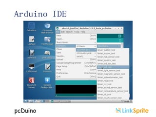
![OpenCV
#!/usr/bin/env python
#coding=utf-8
import os
from PIL import Image, ImageDraw
import cv
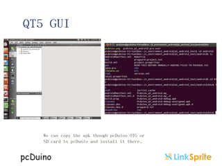
def detect_object(image):
grayscale = cv.CreateImage((image.width, image.height), 8, 1)
cv.CvtColor(image, grayscale, cv.CV_BGR2GRAY)
cascade = cv.Load("/usr/share/opencv/haarcascades/haarcascade_frontalface_alt_tree.xml")
rect = cv.HaarDetectObjects(grayscale, cascade, cv.CreateMemStorage(), 1.1, 2,
cv.CV_HAAR_DO_CANNY_PRUNING, (20,20))
result = []
for r in rect:
result.append((r[0][0], r[0][1], r[0][0]+r[0][2], r[0][1]+r[0][3]))
return result](https://image.slidesharecdn.com/pcduinosharc-140210105006-phpapp02/85/Introduction-to-pcDuino-49-320.jpg)

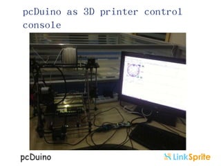
![Home Automation:IP controllable LED
#include ‚sys/socket.h‛
#include ‚netinet/in.h‛
#include ‚arpa/inet.h‛
#include
‚sys/types.h‛
void loop()
{
n = read(connfd, sendBuff, strlen(sendBuff) );
int led_pin = 2;
int listenfd = 0, connfd = 0;
int n;
struct sockaddr_in serv_addr;
char sendBuff[1025];
time_t ticks;
if(n>0)
{
if(sendBuff[0]=='O') digitalWrite(led_pin,
HIGH); // set the LED on
if(sendBuff[0]=='F') digitalWrite(led_pin,LOW);
// set the LED off
}
}
void setup()
{
led_pin = 2;
pinMode(led_pin, OUTPUT);
listenfd = socket(AF_INET, SOCK_STREAM, 0);
memset(serv_addr, '0', sizeof(serv_addr));
memset(sendBuff, '0', sizeof(sendBuff));
serv_addr.sin_family = AF_INET;
serv_addr.sin_addr.s_addr = htonl(INADDR_ANY);
serv_addr.sin_port = htons(5000);
bind(listenfd, (struct sockaddr*) serv_addr, sizeof(serv_addr));
listen(listenfd, 10);
connfd = accept(listenfd, (struct sockaddr*)NULL, NULL);
}](https://image.slidesharecdn.com/pcduinosharc-140210105006-phpapp02/85/Introduction-to-pcDuino-57-320.jpg)


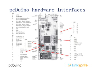
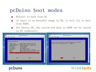
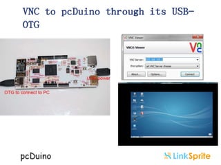
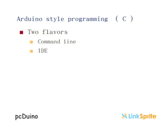
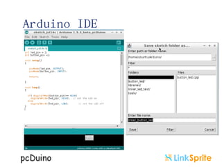
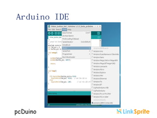
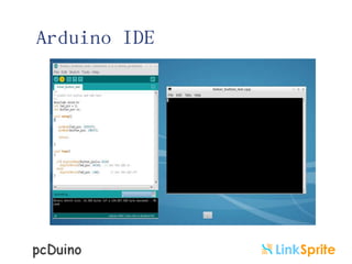
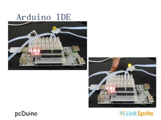
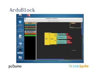
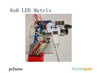
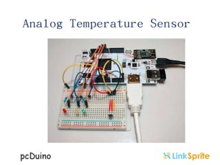
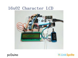
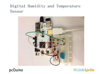
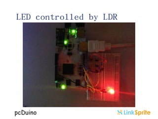
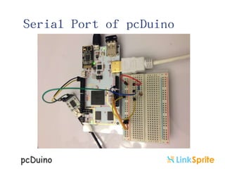
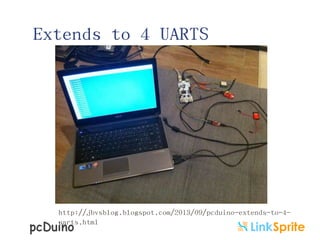
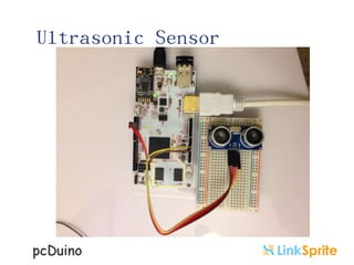
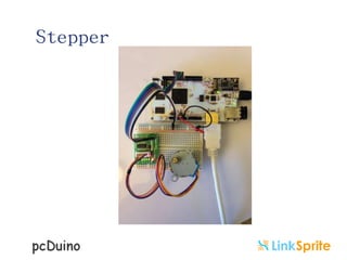
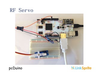
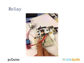
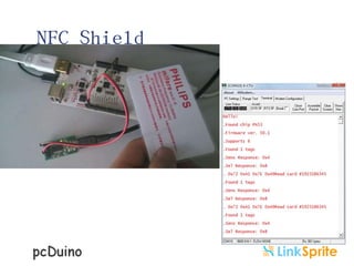
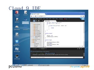
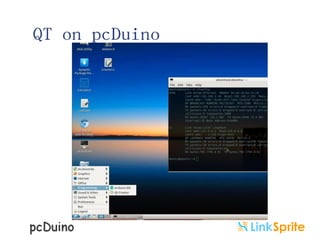
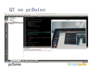
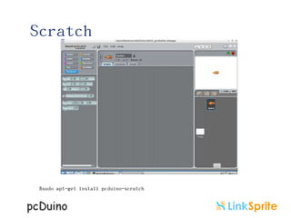
The document discusses pcDuino, an open source hardware and software platform. It can be programmed under Ubuntu Linux using C, Python, Java, and other languages. It also runs Android and supports Arduino-style programming under Android. The pcDuino combines the processing power of a mini PC with Arduino compatibility. It has multiple models that support functions like WiFi, Ethernet, HDMI output, and working with shields. Programming examples and guides are provided for C, Python, OpenCV, Cloud 9 IDE, QT, Scratch, Go and home automation using TCP/IP.