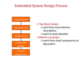
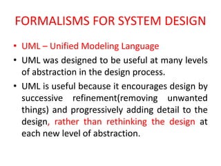
This document provides an introduction to embedded computing and ARM processors. It discusses complex systems and microprocessors, embedded system design processes, and provides an example design of a model train controller. It introduces instruction sets and describes the ARM processor, including its CPU, programming input/output, supervisor mode, exceptions and traps, co-processors, and memory system mechanisms. It also discusses CPU performance and power consumption considerations for embedded systems.
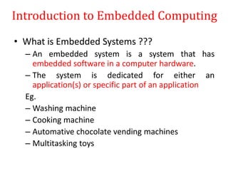
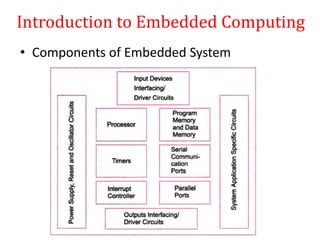
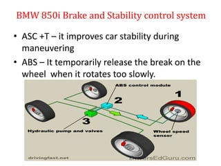


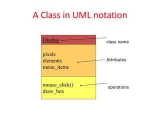
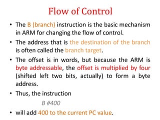
![An object in UML notation
d1: Display
pixels: array[] of pixels
elements
menu_items
object name
class name
attributes](https://image.slidesharecdn.com/introductiontoembeddedcomputingandarmprocessors-190809092242/85/Introduction-to-embedded-computing-and-arm-processors-38-320.jpg)
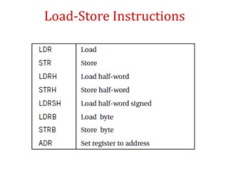
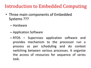
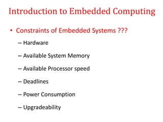
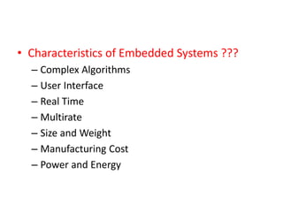
![Load-Store Instructions
• LDR r0,[r1]
• LDR r0,[r1-r2]
• LDR r0,[r1, #5]
• ADR r1, FOO](https://image.slidesharecdn.com/introductiontoembeddedcomputingandarmprocessors-190809092242/85/Introduction-to-embedded-computing-and-arm-processors-91-320.jpg)