

Recommended
Recommended
More Related Content
Similar to 181015 muna-fichas nebulizada-email
Recently uploaded
Recently uploaded (20)
181015 muna-fichas nebulizada-email
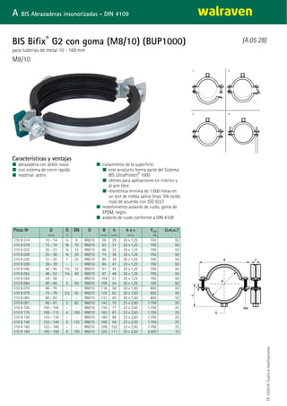
- 1. M8/10 para tuberías de metal 10 - 169 mm BIS Bifix® G2 con goma (M8/10) (BUP1000) (A 05 28) A BIS Abrazaderas insonorizadas - DIN 4109 Características y ventajas ■ abrazadera con doble rosca ■ con sistema de cierre rápido ■ material: acero ■ tratamiento de la superficie: ■ este producto forma parte del Sistema BIS UltraProtect® 1000 ■ idóneo para aplicaciones en interior y al aire libre ■ resistencia mínima de 1.000 horas en un test de niebla salina (max. 5% óxido rojo) de acuerdo con ISO 9227 ■ revestimiento aislante de ruido, goma de EPDM, negro ■ aislante de ruido conforme a DIN 4109 Pieza Nº D D DN G B h b x s Fa,z U.m.v.1 (mm) (") (mm) (mm) (mm) (N) 310 8 014 10 - 14 ¼ 8 M8/10 59 29 20 x 1,25 700 50 310 8 019 15 - 19 ⅜ 10 M8/10 63 31 20 x 1,25 700 50 310 8 023 20 - 23 ½ 15 M8/10 68 33 20 x 1,25 700 50 310 8 028 25 - 28 ¾ 20 M8/10 74 36 20 x 1,25 700 50 310 8 035 31 - 35 1 25 M8/10 80 39 20 x 1,25 700 50 310 8 039 36 - 39 - - M8/10 84 41 20 x 1,25 700 50 310 8 045 40 - 45 1¼ 32 M8/10 91 45 20 x 1,25 700 50 310 8 052 48 - 52 1½ 40 M8/10 97 48 20 x 1,25 700 50 310 8 058 54 - 58 - - M8/10 104 51 20 x 1,25 700 50 310 8 064 60 - 64 2 50 M8/10 109 54 20 x 1,25 700 50 310 8 070 66 - 70 - - M8/10 118 58 20 x 1,50 800 50 310 8 079 75 - 79 2½ 65 M8/10 125 62 20 x 1,50 800 50 310 8 083 80 - 83 - - M8/10 131 65 20 x 1,50 800 50 310 8 091 88 - 91 3 80 M8/10 142 70 23 x 2,00 1.700 25 310 8 105 100 - 105 - - M8/10 155 77 23 x 2,00 1.700 25 310 8 115 108 - 115 4 100 M8/10 163 81 23 x 2,00 1.700 25 310 8 130 125 - 130 - - M8/10 180 89 23 x 2,00 1.700 25 310 8 140 133 - 140 5 125 M8/10 189 94 23 x 2,00 1.700 25 310 8 160 152 - 160 - - M8/10 208 102 23 x 2,00 1.700 25 310 8 169 165 - 169 6 150 M8/10 225 111 25 x 2,50 2.000 10 ES10/2018-Sujetoamodificaciones
- 2. fijando a carril, placas de pared, etc. BIS Varillas roscadas (BUP1000) (K 55 08) K BIS Accesorios de fijación Características y ventajas ■ de acuerdo con DIN 976-1 ■ material: acero, clase 4.8 de resistencia ■ tratamiento de la superficie: ■ este producto forma parte del Sistema BIS UltraProtect® 1000 ■ idóneo para aplicaciones en interior y al aire libre ■ resistencia mínima de 1.000 horas en un test de niebla salina (max. 5% óxido rojo) de acuerdo con ISO 9227 ■ seguridad contra incendios probada Pieza Nº Tipo Rosca (M) L At.peq. 6308 1 008 DIN 976-1 M8 1 m 50 6308 2 008 DIN 976-1 M8 2 m 25 6308 1 010 DIN 976-1 M10 1 m 25 6308 2 010 DIN 976-1 M10 2 m 20 6308 1 012 DIN 976-1 M12 1 m 20 6308 2 012 DIN 976-1 M12 2 m 15 6308 1 016 DIN 976-1 M16 1 m 20 6308 2 016 DIN 976-1 M16 2 m 10 Desde M10 seguridad probada contra incendios. ES10/2018-Sujetoamodificaciones Complementarios BIS Manguitos roscados hexagonales - 390 BIS Conectores de soporte
- 3. Anclaje con rosca interior de acero inoxidable estándar WDI1 Anclaje hembra acero inoxidable (L 03 15) L BIS Fijaciones Características y ventajas ■ Procedimiento de instalación sencillo y rápido ■ Capacidad de carga media ■ Hecho de acero inoxidable para uso en ambiente atmosférico externo ■ Sin collarín para instalación de anclajes a profundidades de orificio mayores ■ material: acero inoxidable ■ Homologación ETA ETAG001 Parte 6 para uso múltiple en aplicaciones no estructurales ■ Resistencia al fuego clase R30-R120 para el diseño de anclajes expuestos al fuego ■ tipo de substrato: ■ hormigón fisurado ■ hormigón no fisurado Pieza Nº Códig o Tamañ o L d0 h0 hmin hnom Carga de tensió n C20 / 25 Hormi gón Factor de seguri dad parcial U.m.v. 1 U.m.v. 2 (mm) (mm) (mm) (mm) (kN) (yMc) 610 3 708 WDI1 SSt 8x30 M8 30 mm 10 ≥ 32 80 ≥ 30 0,68* 2,10 100 600 610 3 710 WDI1 SSt 10x40 M10 40 mm 12 ≥ 42 80 ≥ 40 1,09* 2,10 50 500 610 3 712 WDI1 SSt 12x50 M12 50 mm 15 ≥ 53 100 ≥ 50 1,56* 2,10 50 300 610 3 716 WDI1 SSt 16x65 M16 65 mm 20 ≥ 70 130 ≥ 65 2,81* 2,10 25 200 * = Cargas recomendadas: se indican para uso múltiple para aplicaciones no estructurales de acuerdo con ETAG001, Parte 6; aplicar a los anclajes correctamente instalados a la profundidad máxima de empotramiento; incluir un factor de seguridad parcial y un factor de seguridad parcial total para la acción de 1.4. El factor de seguridad parcial para la acción depende del tipo de carga y se tomará de las regulaciones nacionales. Todos los modos de falla de anclaje y toda la evaluación técnica europea del producto pertinente deben considerarse para el diseño del anclaje. Para más información, por favor consultar bases ETA. ES10/2018-Sujetoamodificaciones Complementarios WDI1 Herramienta de instalación WIS Cepillo WIS Bomba sopladora Complementarios WSDS+ Drill with Stopper WSDS Taladro con 3 aristas
- 14. walraven DECLARATION OF PERFORMANCE DoP No. 16/0783-WDI1 1. Unique identification code of the product-type: Walraven Drop In Anchor WDI1 2. Type, batch or serial number or any other element allowing identification of the construction product as required pursuant to Article 11(4): See: ETA-16/0783 Charge number: See product packaging 3. Intended use or uses of the construction product, in accordance with the applicable harmonized technical specification, as foreseen by the manufacturer: Generic type Steel expansion anchors For use in cracked and non-cracked concrete C20/25 to C50/60 acc. To EN 206:2000-12 Material WDI1, WDI1L Drop In Anchors are deformation-controlled expansion anchors in sizes of M6, M8, M10, M12, M16 and M20. WDI1 SSt Anchors are deformation-controlled expansion anchors in sizes of M6, M8, M10, M12, M16. The anchors WDI1 and WDI1L are made of galvanized steel and WDI1 SSt are made of stainless steel. Use category Deformation-controlled steel expansion anchors in sizes M6, M8, M10, M12, M16 and M20, for multiple use for non-structural applications in concrete Loading Loading static or quasi-static 4. Name, registered trade name or registered trade mark and contact address of the manufacturer as required pursuant to Article 11(5): J. van Walraven Holding B.V., Industrieweg 5, 3641 RK Mijdrecht, The Netherlands 5. Where applicable, name and contact address of the authorized representative whose mandate covers the tasks specified in Article 12(2): 6. System or systems of assessment and verification of constancy of performance of the construction product as set out in Annex V: System 2+ 7. In case of the declaration of performance concerning a construction product covered by a harmonized standard: 1 www.walraven.com
- 15. Essential Characteristics Performance Harmonized Technical Specification ETA 13/0584, Annex Cl ETAG 001 Part 6Edge distances and spacing 13/0584, Annex C2Characteristic resistance under fire exposure Characteristic resistance for all load directions ETA 13/0584, Annex Cl walraven 8. In case of the declaration of performance concerning a construction product for which a European Technical Assess ment has been issued: Technical Assessment Body: Instytut Techniki Budowlanej European Technical Assessment: ETA 16/0783 European Assessment Document: ETAG 001:06 Notified body/ies: 1488 The notified body 1488 performed under system 1: (i) determination of the product type on the basis of type testing (including sampling), type calculation, tabulated values or descriptive documentation of the product; (ii) initial inspection of the manufacturing plant and of factory production control; (iii) continuous surveillance, assessment and evaluation of factory production control and issued: Certificate of constancy of performance: 1488-CPR-0465/Z 9. Declared performance/s: Table Cl: Characteristic resistance - VVDI1 DROP IN ANCHOR and WDI1L DROP IN ANCHOR LIPPED (design acc. to ETAG 001, Annex C, method C) R-DCA and R-DCL Property M6 M8 M10 class M12 M16 M20 All load directions (fastening screw or threaded ro d property class 2 4 8) Characteristic resistance in cracked and non-cracked concrete C20/25 to C50/60 FRk [kN] 2 4.8 1,52 3,01 4,57 6,43 13,31 17,38 Partial safety factor (installation safety factor y2 =1,4 included) YM 1 E-1 2,1 Spacing Scr [111/11] 200 260 320 Edge distance CC, [rnifi] 150 195 240 Shear load with lever arm Characteristic resistance M°Fik,s 2 [Nm] 4.8 6 15 30 52 133 260 Characteristic resistance M°Rk,s 2 [Nm] 5.8 8 19 37 66 167 325 Characteristic resistance M'Fik,s 2 [Nm] 6.8 9 23 45 79 200 390 Characteristic resistance M°Rk,s 2 [Nm] 8.8 12 30 60 105 267 520 Partial safety factor 1 Vms1 [-] - 1,25 'in the absence of other national regulations 2 characteristic bending moment for the equation (5.5) in ETAG 001, Annex C 2 www.walraven.com
- 16. Fire resistance class RWDI1 DROP IN ANCHOR and WDI1L DROP IN ANCHOR LIPPED screw or threaded eloproperty Characteristic resistance FRkfi 1 class [kN] M8 4.8) 0,4 M10 0,9 M12 1,6 M16 3,1 M20 4,3 All load directions (fastening R30 R60 [kN] 0,3 0,8 1,3 2,4 3,7 R90 [kN] 0,3 0,6 1,1 2,0 3,2 R120 [kN] 0,2 0,5 0,8 1,6 2,5 Spacing Scr,f1 [mm] 4 xha Edge distance Ccrfi [mm] 2 x hef The design method covers anchors with a fire attack from one side only. In case of fire attack from more than one side, the edge distance shall be 300 mm. walraven Table C2: Characteristic resistance - WDI1 SSt DROP IN ANCHOR (design acc. to ETAG 001, Annex C, method C) WDI1 SSt DROP IN ANCHOR Property class m6 M8 M10 M12 M16 All load directions (fastening screw or threaded rod property class A4-70) Characteristic resistance in cracked and non-cracked concrete C20125 to C50160 F Rk [kN] A4-70 1,00 2,01 3,20 4,59 8,27 Partial safety factor (installation safety factor p = 1,4 included) Ym 1 [-] 2,1 [Mal] - 200 260Spacing S cr [mm] 150 195Edge distance Cu Shear load with lever arm Characteristic resistance M°Rk,S 2 (11m) A4-70 11 26 52 92 233 Partial safety factor yms 1 [-] - 1,25 'in the absence of other national regulations 2 characteristic bending moment M°Rics for the equation (5.5) in ETAG 001, Annex C Table C3: Characteristic resistance under fire exposure in concrete C20/25 to C50/60 - WDI1 DROP IN ANCHOR and WDI1L DROP IN ANCHOR LIPPED (design acc. to ETAG 001, Annex C, method C) 1 in the absence of other national regulations a partial safety factor ym,fr 1,0 is recommended 3 www.walraven.com
- 17. Fire resistance class WDI1 SSt DROP IN ANCHOR M8 M10 M12 M16 All load directions (fastening screw or threaded rod property class A4-70) R30 Characteristic resistance FRk,fi 1 [kN] 0,5 0,8 1,1 2,1 R60 [kN] 0,5 0,8 1,1 2,1 R90 [kN] 0,5 0,8 1,1 2,1 R120 [kN] 0,4 0,6 0,9 1,6 Spacing S cr,fi Edge distance Ccr,fi [mml 4 x her [mm] 2 x hcf The design method covers anchors with a fire attack from one side only. In case of fire attack from more than one side, the edge distance shall be 300 mm. *** *r.** ETA * *** E rh- VAIONALRAVEN HOLDING BN, Industrieweg 5 3641 FOC MIJDRECHT walraven Table C4: Characteristic resistance under fire exposure in co ncrete C20/25 to C50/60 - WDII SSt DROP IN ANCHOR (design acc. to ETAG 001, Annex C, method C) ' in the absence of other national regulations a partial safety factor yme = 1,0 is recommended Technical Documentation and / or Specific Technical Documentation: ETA-16/0783 of 09/26/2016 10. The performance of the product identified in points 1 and 2 is in conformity with the declared performance in point 9. This declaration of performance is issued under the sole responsibility of the manufacturer identified in point 4. Signed for and on behalf of the manufacturer by: 4 www.walraven.com
- 18. fijación a pared BIS Placas de pared 670 y 671 en acero inox - 612 (M 65 05) M BIS Fijaciones en acero inoxidable Características y ventajas ■ los orificios se encuentran a 90º cada uno del otro para simplificar la fijación ■ con tuerca de conexión soldada de resistencia ■ Pieza Nº 671 7 021: tuerca de conexión soldada con CO2 ■ Pieza Nº 670 7 0XX: material: acero inoxidable 1.4301 (AISI 304) ■ Pieza Nº 671 7 0XX: material: acero inoxidable 1.4404 (AISI 316L) Pieza Nº G L B s d1 d2 k Fa,z U.m.v.1 U.m.v.2 (mm) (mm) (mm) (mm) (mm) (N) 670 7 006 M6 80 mm 25 3,0 15 x 8,5 15 x 8,5 50 2.500 50 125 670 7 008 M8 80 mm 25 3,0 15 x 8,5 15 x 8,5 50 2.500 50 250 670 7 010 M10 80 mm 25 3,0 15 x 8,5 15 x 8,5 50 2.500 50 250 671 7 010 M10 145 mm 35 4,0 30 x 11,0 25 x 11,0 100 3.000 40 - 671 7 021 G½" 145 mm 35 4,0 30 x 11,0 25 x 11,0 100 3.000 50 - ES10/2018-Sujetoamodificaciones Complementarios BIS Varillas roscadas en acero inox - 530
- 19. Características y ventajas ■ gran capacidad de carga ■ Prefijación y fijación pasante ■ Hecho de acero inoxidable para uso en ambiente atmosférico externo ■ Sus dos profundidades de incrustación aportan flexibilidad de instalación ■ material: acero inoxidable ■ Homologación ETA Opción 1 para hormigón fisurado y no fisurado ■ Resistencia al fuego clase R30-R120 para el diseño de anclajes expuestos al fuego ■ tipo de substrato: ■ hormigón fisurado ■ hormigón no fisurado ■ stone Anclaje expansivo de acero inoxidable de altas prestaciones para hormigón fisurado (L 03 50)WTB1 Anclaje macho inox L BIS Fijaciones Pieza Nº Código Tamaño L d0 h0 hmin hnom tfix,max Carga de tensión C20 / 25 Hormigón sin fisurar Carga de tensión C20 / 25 Hormigón fisurado Factor de seguridad parcial U.m.v.1 (mm) (mm) (mm) (mm) (mm) (kN) (kN) (yMc) 6098 7 1080 WTB1 SSt 8x75 M8 75 mm 8 55 100 55 10 3,57* 2,38* 1,80 100 6098 7 1081 WTB1 SSt 8x115 M8 115 mm 8 55 100 55 50 3,57* 2,38* 1,80 100 6098 7 1100 WTB1 SSt 10x95 M10 95 mm 10 69 100 69 15 7,62* 4,29* 1,50 50 6098 7 1101 WTB1 SSt 10x130 M10 130 mm 10 69 100 69 50 7,62* 4,29* 1,50 50 6098 7 1120 WTB1 SSt 12x125 M12 125 mm 12 80 140 80 30 11,90* 5,71* 1,50 50 6098 7 1121 WTB1 SSt 12x150 M12 150 mm 12 80 140 80 55 11,90* 5,71* 1,50 50 * = Cargas recomendadas: se indican para anclajes individuales; aplicar a los anclajes correctamente instalados a la profundidad máxima de empotramiento; incluir un factor de seguridad parcial y un factor de seguridad parcial total para la acción de 1.4. El factor de seguridad parcial para la acción depende del tipo de carga y se tomará de las regulaciones nacionales. Todos los modos de falla de anclaje y toda la evaluación técnica europea del producto pertinente deben considerarse para el diseño del anclaje. Para más información, por favor consultar bases ETA. ES10/2018-Sujetoamodificaciones Complementarios WIS Cepillo WIS Bomba sopladora WSDS+ Drill with Stopper Complementarios WSDS Taladro con 3 aristas
- 20. Technical and Test Institute for Construction Prague Prosecká 811/76a 190 00 Prague Czech Republic eota@tzus.cz Member of www.eota.eu ETA 17/0343 of 12/04/2017 – Page 1 of 11 090-038217 European Technical Assessment ETA 17/0343 of 12/04/2017 Technical Assessment Body issuing the ETA: Technical and Test Institute for Construction Prague Trade name of the construction product Walraven Throughbolt anchor WTB1 SST Product family to which the construction product belongs Product area code: 33 Torque controlled expansion anchor for use in cracked and uncracked concrete Manufacturer J. van Walraven Holding B.V. Industrieweg 5 3641 RK Mijdrecht The Netherland Manufacturing plant Walraven Factory A2 This European Technical Assessment contains 11 pages including 9 Annexes which form an integral part of this assessment This European Technical Assessment is issued in accordance with regulation (EU) No 305/2011, on the basis of EAD 330232-00-0601 Translations of this European Technical Assessment in other languages shall fully correspond to the original issued document and should be identified as such. Communication of this European Technical Assessment, including transmission by electronic means, shall be in full (excepted the confidential Annex(es) referred to above). However, partial reproduction may be made, with the written consent of the issuing Technical Assessment Body - Technical and Test Institute for Construction Prague. Any partial reproduction has to be identified as such
- 21. Page 2 of 11 ETA 17/0343 issued on 12/04/2017 1. Technical description of the product The Walraven Throughbolt anchor WTB1 SST are through-fixing torque-controlled expansion anchors in sizes of M8, M10, M12 and M16. Each type comprises a special bolt with a taper, an expansion sleeve, a hexagonal nut and a washer. The anchors are made from A4 grade stainless steel. The anchor is installed in a drilled hole; tightening the nut draws the cone into the sleeve. The expansion of this sleeve applies the anchorage. The installed anchor is shown in Annex 1. 2. Specification of the intended use in accordance with the applicable EAD The performances given in Section 3 are only valid if the anchor is used in compliance with the specifications and conditions given in Annex B. The provisions made in this European Technical Assessment are based on an assumed working life of the anchor of 50 years. The indications given on the working life cannot be interpreted as a guarantee given by the producer, but are to be regarded only as a means for choosing the products in relation to the expected economically reasonable working life of the works. 3. Performance of the product and references to the methods used for its assessment 3.1 Mechanical resistance and stability (BWR 1) Essential characteristic Performance Characteristic resistance (static and quasi-static loading) See Annex C 1 and C 2 Displacement See Annex C 1 and C 2 3.2 Safety in case of fire (BWR 2) Essential characteristic Performance Reaction to fire Class A1 according to EN 13501-1 Resistance to fire Seen Annex C 3 4. Assessment and verification of constancy of performance (AVCP) system applied with reference to its legal base According to the Decision 97/463/EC of the European Commission1 , the system 1 of assessment verification of constancy of performance (see Annex V to the Regulation (EU) No 305/2011) apply. 5. Technical details necessary for the implementation of the AVCP system, as provided in the applicable EAD Technical details necessary for the implementation of the AVCP system are laid down in the control plan deposited at Technical and Test Institute for Construction Prague. Issued in Prague on 12.04.2017 By Ing. Mária Schaan Head of the Technical Assessment Body 1 Official Journal of the European Communities L 198/31 25.7.1997
- 22. Page 3 of 11 ETA 17/0343 issued on 12/04/2017 Walraven Throughbolt anchor WTB1 SST - Installed anchor Walraven Throughbolt anchor WTB1 SST - components Nut Washer Anchor body Expansion sleeve Walraven Throughbolt anchor WTB1 SST Annex A 1Product description Installed conditions and components
- 23. Page 4 of 11 ETA 17/0343 issued on 12/04/2017 Table A1 - Materials Component Material Anchor body Steel rod on coil cold forged bolts Steel grade 1.4578, according EN 10263-5 Expansion sleeve Steel grade 1.4401, according EN 10088-2 Hexagonal nut according DIN 934 Washer according DIN 125A or DIN 9021 Table A2 – Material properties Component M8 M10 M12 M16 Anchor body – ultimate tensile strength [N/mm2 ] 600-700 600-700 550-650 550-650 Expansion sleeve – ultimate tensile strength [N/mm2 ] 530-680 530-680 530-680 530-680 Table A3 – Marking M8 Bolt length [mm] 60 65 75 80 85 90 95 100 105 115 120 140 150 160 Head marking B b C d D e E F f G H K L M Bolt marking -/10 -/15 10/25 15/30 20/35 25/40 30/45 35/50 40/55 50/65 55/70 75/90 85/100 95/110 M10 Bolt length [mm] 65 80 85 90 95 115 120 130 140 150 180 Head marking B D d e E G H J K L P Bolt marking -/5 -/20 5/25 10/30 15/35 35/55 40/60 50/70 60/80 70/90 100/120 M12 Bolt length [mm] 80 100 105 110 115 120 125 135 140 150 160 180 200 220 240 250 260 280 Head marking D F f G g h H J K L M P R S T U V X Bolt marking -/5 5/25 10/30 15/35 20/40 25/45 30/50 40/60 45/65 55/75 65/85 85/105 105/125 125/145 145/165 155/175 165/185 185/205 M16 Bolt length [mm] 100 105 125 130 140 150 160 180 200 220 250 280 300 Head marking F f H J K L M P R S U X Y Bolt marking -/5 -/10 5/25 10/30 20/40 30/50 40/60 60/80 80/100 100/120130/150160/180180/200 Walraven Throughbolt anchor WTB1 SST Annex A 2Product description Materials Marking
- 24. Page 5 of 11 ETA 17/0343 issued on 12/04/2017 Specifications of intended use Anchorages subject to: Static and quasi-static load. Base materials Cracked or uncracked concrete. Reinforced or unreinforced normal weight concrete of strength class C20/25 at minimum and C50/60 at maximum according EN 206-1:2000-12. Use conditions (Environmental conditions) Structures subject to dry internal conditions. Structures subject to external atmospheric exposure (including industrial and marine environment) or exposure to permanently damp internal condition, if no particular aggressive conditions exist. Note: Particular aggressive conditions are e.g. permanent, alternating immersion in seawater or the splash zone of seawater, chloride atmosphere of indoor swimming pools or atmosphere with extreme chemical pollution (e.g. in desulphurization plants or road tunnels where de-icing materials are used). Design: The anchorages are designed under the responsibility of an engineer experienced in anchorages and concrete work. Verifiable calculation notes and drawings are prepared taking account of the loads to be anchored. The position of the anchor is indicated on the design drawings. Anchorages under static or quasi-static actions are designed for design method A in accordance with FprEN 1992-4:2016 Installation: Anchor installation carried out by appropriately qualified personnel and under the supervision of the person responsible for technical matters of the site. Use of the anchor only as supplied by the manufacturer without exchanging any components of the anchor. Anchor installation in accordance with the manufacturer’s specifications and drawings using the appropriate tools. Effective anchoring depth, edge distance and spacing not less than the specified values without minus tolerance. In case of aborted drill hole: new drilling at a minimum distance away of twice the depth of the aborted hole or smaller distance if the aborted drill hole is filled with high strength mortar and if under shear or oblique tension load it is not in the direction of load application. Walraven Throughbolt anchor WTB1 SST Annex B 1Intended use Specifications
- 25. Page 6 of 11 ETA 17/0343 issued on 12/04/2017 Table B1 - Installation parameters Size Drill hole diameter Bolt length Thread length Hole diameter in fixture Standard embedment Reduced embedment Installation torqueMin. hole depth Effective embedment depth Max. fixture thickness Min. hole depth Effective embedment depth Max. fixture thickness d0 [mm] l [mm] lG [mm] df [mm] h0 [mm] hef [mm] tfix [mm] h0 [mm] hef [mm] tfix [mm] Tinst [N.m] M8 8 60 25 9 - - - 40 32 10 15 65 30 9 - - - 40 32 15 75 35 9 55 47 10 40 32 25 80 40 9 55 47 15 40 32 30 85 45 9 55 47 20 40 32 35 90 50 9 55 47 25 40 32 40 95 55 9 55 47 30 40 32 45 100 60 9 55 47 35 40 32 50 105 65 9 55 47 40 40 32 55 115 75 9 55 47 50 40 32 65 120 80 9 55 47 55 40 32 70 140 100 9 55 47 75 40 32 90 150 100 9 55 47 85 40 32 100 160 100 9 55 47 95 40 32 110 M10 10 65 21 11 - - - 49 39 5 30 80 31 11 - - - 49 39 20 85 36 11 69 59 5 49 39 25 90 41 11 69 59 10 49 39 30 95 46 11 69 59 15 49 39 35 115 66 11 69 59 35 49 39 55 120 71 11 69 59 40 49 39 60 130 81 11 69 59 50 49 39 70 140 91 11 69 59 60 49 39 80 150 101 11 69 59 70 49 39 90 180 100 11 69 59 100 49 39 120 M12 12 80 30 13 - - - 60 48 5 50 100 40 13 80 68 5 60 48 25 105 45 13 80 68 10 60 48 30 110 50 13 80 68 15 60 48 35 115 55 13 80 68 20 60 48 40 120 60 13 80 68 25 60 48 45 125 65 13 80 68 30 60 48 50 135 75 13 80 68 40 60 48 60 140 80 13 80 68 45 60 48 65 150 90 13 80 68 55 60 48 75 160 100 13 80 68 65 60 48 85 180 100 13 80 68 85 60 48 105 200 100 13 80 68 105 60 48 125 220 100 13 80 68 125 60 48 145 240 100 13 80 68 145 60 48 165 250 100 13 80 68 155 60 48 175 260 100 13 80 68 165 60 48 185 280 100 13 80 68 185 60 48 205 M16 16 100 30 18 - - - 80 65 5 100 105 35 18 - - - 80 65 10 125 45 18 100 85 5 80 65 25 130 50 18 100 85 10 80 65 30 140 60 18 100 85 20 80 65 40 150 70 18 100 85 30 80 65 50 160 80 18 100 85 40 80 65 60 180 100 18 100 85 60 80 65 80 200 100 18 100 85 80 80 65 100 220 100 18 100 85 100 80 65 120 250 100 18 100 85 130 80 65 150 280 100 18 100 85 160 80 65 180 300 100 18 100 85 180 80 65 200 Walraven Throughbolt anchor WTB1 SST Annex B 2Intended use Installation parameters
- 26. Page 7 of 11 ETA 17/0343 issued on 12/04/2017 Table B2 - Installation parameters – Minimum spacing and edge distance Size M8 M10 M12 M16 Red1) Std Red1) Std Red Std Red Std Minimum thickness of concrete member hmin [mm] 100 100 100 120 100 140 130 170 Minimum spacing and edge distance in cracked concrete Minimum spacing smiin [mm] 50 55 70 70 120 90 150 135 for edge distance c ≥ [mm] 50 55 70 70 95 75 100 105 Minimum edge distance cmin [mm] 40 40 50 45 70 55 85 70 for spacing s ≥ [mm] 80 70 120 90 150 140 200 200 Minimum spacing and edge distance in uncracked concrete Minimum spacing smin [mm] 50 55 70 70 120 90 150 135 for edge distance c ≥ [mm] 50 55 70 70 95 75 100 105 Minimum edge distance cmin [mm] 50 40 70 50 95 55 100 80 for spacing s ≥ [mm] 50 100 70 115 120 125 150 200 1) Use restricted to anchoring statically indeterminate structural components Pre-torque installation Post-torque installation Walraven Throughbolt anchor WTB1 SST Annex B 2Intended use Installation parameters
- 27. Page 8 of 11 ETA 17/0343 issued on 12/04/2017 Installation instructions 1. Drill a hole of required diameter and depth 2. Clear the hole of drilling dust and debris (using blowpump or equivalent method) 3. Lightly tap the throughbolt through the fixture into hole with a hammer, until fixing depth is reached 4. Tighten to the recommended torque 5. Assembled condition of anchor Walraven Throughbolt anchor WTB1 SST Annex B 3Intended use Installation instructions
- 28. Page 9 of 11 ETA 17/0343 issued on 12/04/2017 Table C1 – Characteristic resistance under tension load Steel failure Size M8 M10 M12 M16 Red1) Std Red1) Std Red Std Red Std Characteristic resistance NRk,s [kN] 21,2 33,6 44,8 82,6 Partial safety factor γMs [-] 1,5 1,5 1,5 1,5 Pull-out failure Characteristic resistance in cracked concrete C20/25 NRk,p [kN] 3,0 6,0 7,5 9,0 9,0 12,0 16,0 25,0 Characteristic resistance in uncracked concrete C20/25 NRk,p [kN] 7,5 9,0 12,0 16,0 - 25,0 - - Installation safety factor γ2 2) = γinst 3)4) [-] 1,2 1,2 1,2 1,0 1,0 1,0 1,0 1,0 Increasing factor C30/37 1,07 1,16 1,07 1,26 1,16 1,23 1,18 1,18 Cracked and uncracked concrete C40/50 ψc [-] 1,13 1,33 1,13 1,52 1,32 1,45 1,37 1,37 C50/60 1,20 1,50 1,20 1,78 1,49 1,67 1,55 1,55 Concrete cone failure Characteristic resistance in uncracked concrete C20/25 NRk,c [kN] - - - - 16,8 - 26,4 39,5 Factor for uncracked concrete k1 2) =kucr 3) [-] 10,1 kucr,N 4) [-] 11,0 Factor for cracked concrete k1 2) =kucr 3) [-] 7,2 kucr,N 4) [-] 7,7 Installation safety factor γ2 2) = γinst 3)4) [-] 1,2 1,2 1,2 1,0 1,0 1,0 1,0 1,0 Effective anchorage depth hef [mm] 32 47 39 59 48 68 65 85 Spacing scr,N [mm] 96 141 117 177 144 204 195 255 Edge distance ccr,N [mm] 48 71 59 89 72 102 98 128 Splitting failure Spacing scr,sp [mm] 160 240 200 300 250 340 320 430 Edge distance ccr,sp [mm] 80 120 100 150 125 170 160 215 Installation safety factor γ2 2) = γinst 3)4) [-] 1,2 1,2 1,2 1,0 1,0 1,0 1,0 1,0 1) Use restricted to anchoring statically indeterminate structural components 2) parameter for design according to EOTA ETAG 001 Annex C 3) parameter for design according to CEN/TS 1992-4-4:2009 4) parameter for design according to FprEN 1992-4:2016 Table C2 – Displacement under tension load Size M8 M10 M12 M16 Red1) Std Red1) Std Red Std Red Std Tension load in cracked concrete N [kN] 1,2 2,4 3,0 4,3 4,3 5,7 7,6 11,9 Displacement δN0 [mm] 1,1 0,5 0,5 1,2 0,8 1,0 0,2 1,0 δN∞ [mm] 1,8 1,3 0,8 1,2 1,0 1,3 0,6 1,1 Tension load in uncracked concrete N [kN] 3,0 3,6 4,8 7,6 8,0 11,9 12,6 18,8 Displacement δN0 [mm] 0,1 0,3 0,2 0,2 0,1 0,5 0,3 0,5 δN∞ [mm] 0,8 1,3 0,8 1,2 1,0 1,3 0,6 1,1 1) Use restricted to anchoring statically indeterminate structural components Walraven Throughbolt anchor WTB1 SST Annex C 1Performances Characteristic resistance under tension load Displacement under tension load
- 29. Page 10 of 11 ETA 17/0343 issued on 12/04/2017 Table C3 – Characteristic resistance under shear load Steel failure without lever arm Size M8 M10 M12 M16 Red1) Std Red1) Std Red Std Red Std Characteristic resistance V0 Rk,s [kN] 11,7 18,5 24,6 45,4 Ductility factor k7 [-] 0,8 0,8 0,8 0,8 Partial safety factor γMs [-] 1,25 1,25 1,25 1,25 Steel failure with lever arm Characteristic resistance M0 Rk,s [Nm] 22 45 72 180 Partial safety factor γMs [-] 1,25 1,25 1,25 1,25 Concrete pry-out failure Characteristic resistance concrete C20/25 VRk,cp [kN] - - 14,7 - - - - - Factor k8 [-] - - 1,2 - - - - - Installation safety factor γ2 2) = γinst 3)4) [-] - - 1,2 - - - - - Concrete edge failure Effective length of anchor ℓf [mm] 32 47 39 59 48 68 65 85 Anchor diameter dnom [mm] 8 10 12 16 Installation safety factor γ2 2) = γinst 3)4) [-] 1,2 1,2 1,2 1,0 1,0 1,0 1,0 1,0 1) Use restricted to anchoring statically indeterminate structural components 2) parameter for design according to EOTA ETAG 001 Annex C 3) parameter for design according to CEN/TS 1992-4-4:2009 4) parameter for design according to FprEN 1992-4:2016 Table C4 – Displacement under shear load Size M8 M10 M12 M16 Red1) Std Red1) Std Red Std Red Std Tension load in cracked and uncracked concrete V [kN] 6,7 6,7 5,8 10,6 14,1 14,1 25,9 25,9 Displacement δV0 [mm] 3,0 3,0 1,5 2,7 2,5 2,5 2,2 2,2 δV∞ [mm] 4,5 4,5 2,2 4,1 3,8 3,8 3,8 3,3 1) Use restricted to anchoring statically indeterminate structural components Walraven Throughbolt anchor WTB1 SST Annex C 2Performances Characteristic resistance under shear load Displacement under shear load
- 30. Page 11 of 11 ETA 17/0343 issued on 12/04/2017 Table C5 – Characteristic values of resistance to tension load under fire exposure1) Size M8 M10 M12 M16 Red2) Std Red2) Std Red Std Red Std Characteristic fire resistance duration at 30 minutes Steel failure NRk,s,fi [kN] 0,7 0,7 1,5 1,5 2,5 2,5 4,7 4,7 Pull-out failure NRk,p,fi [kN] 0,8 1,5 1,9 2,3 2,3 3,0 4,0 6,3 Concrete cone failure NRk,c,fi [kN] 1,0 2,7 1,7 4,8 2,9 6,9 6,1 12,0 Characteristic fire resistance duration at 60 minutes Steel failure NRk,s,fi [kN] 0,6 0,6 1,2 1,2 2,1 2,1 3,9 3,9 Pull-out failure NRk,p,fi [kN] 0,8 1,5 1,9 2,3 2,3 3,0 4,0 6,3 Concrete cone failure NRk,c,fi [kN] 1,0 2,7 1,7 4,8 2,9 6,9 6,1 12,0 Characteristic fire resistance duration at 90 minutes Steel failure NRk,s,fi [kN] 0,4 0,4 0,9 0,9 1,7 1,7 3,1 3,1 Pull-out failure NRk,p,fi [kN] 0,8 1,5 1,9 2,3 2,3 3,0 4,0 6,3 Concrete cone failure NRk,c,fi [kN] 1,0 2,7 1,7 4,8 2,9 6,9 6,1 12,0 Characteristic fire resistance duration at 120 minutes Steel failure NRk,s,fi [kN] 0,4 0,4 0,8 0,8 1,3 1,3 2,5 2,5 Pull-out failure NRk,p,fi [kN] 0,6 1,2 1,5 1,8 1,8 2,4 3,2 5,0 Concrete cone failure NRk,c,fi [kN] 0,8 2,2 1,4 3,9 2,3 5,5 4,9 9,6 Spacing scr,N [mm] 4 x hef smin [mm] 50 55 70 70 120 90 150 135 Edge distance ccr,N [mm] 2 x hef cmin [mm] cmin = 2 x hef however if the fire attack is from more than one side, the edge distance of the anchor has to be ≥ 300 mm and ≥ 2 x hef 1) In absence of other national regulations the partial safety factor for resistance under fire exposure. M,fi = 1,0 is recommended 2) Use restricted to anchoring statically indeterminate structural components Table C6 – Characteristic values of resistance to shear load under fire exposure Size M8 M10 M12 M16 Red1) Std Red1) Std Red) Std Red Std Characteristic fire resistance duration at 30 minutes Steel failure without lever arm VRk,s,fi [kN] 0,7 1,5 2,5 4,7 Steel failure with lever arm MRk,s,fi [Nm] 0,7 1,9 3,9 10,0 Characteristic fire resistance duration at 60 minutes Steel failure without lever arm VRk,s,fi [kN] 0,6 1,2 2,1 3,9 Steel failure with lever arm MRk,s,fi [Nm] 0,6 1,5 3,3 8,3 Characteristic fire resistance duration at 90 minutes Steel failure without lever arm VRk,s,fi [kN] 0,4 0,9 1,7 3,1 Steel failure with lever arm MRk,s,fi [Nm] 0,4 1,2 2,6 6,7 Characteristic fire resistance duration at 120 minutes Steel failure without lever arm VRk,s,fi [kN] 0,4 0,8 1,3 2,5 Steel failure with lever arm MRk,s,fi [Nm] 0,4 1,0 2,1 5,3 Concrete pry-out failure Factor2) k8 [-] - - 1,2 - - - - - Concrete edge failure The characteristic resistance V0 Rk,c,fi in concrete C20/25 to C50/60 is determined by: V0 Rk,c,fi = 0,25 x V0 Rk,c(≤90) and V0 Rk,c,fi = 0,20 x V0 Rk,c(≤120) with the initial value of the characteristic resistance V0 Rk,c in cracked concrete C20/25 under normal temperature 1) Use restricted to anchoring statically indeterminate structural components 2) The values of factor k8 and relevant values of NRk,c,fi given in the Table C5 have to be considered in the design Walraven Throughbolt anchor WTB1 SST Annex C 3Performances Characteristic values of resistance under fire exposure
- 31. 8. In case of the declaration of performance concerning a construction product for which a European Technical Assess ment has been issued: Technical Assessment Body: Technical and Test Institute for Construction Prague European Technical Approval: ETA-17/0343 edition of 12-04-2017 European Assessment Document: ETAG 001:2 Notified body/ies: 1488 www.walraven.com DECLARATION OF PERFORMANCE DoP No. 17/0343-WTB1 sst 4. Name, registered trade name or registered trade mark and contact address of the manufacturer as required pursuant to Article 11(5): J. van Walraven Holding B.V., Industrieweg 5, 3641 RK Mijdrecht, The Netherlands 5. Where applicable, name and contact address of the authorized representative whose mandate covers the tasks specified in Article 12(2): 6. System or systems of assessment and verification of constancy of performance of the construction product as set out in Annex V: System 1 7. In case of the declaration of performance concerning a construction product covered by a harmonized standard: 1. Unique identification code of the product-type: Walraven Throughbolt Option 1 WTB1 sst 2. Type, batch or serial number or any other element allowing identification of the construction product as required pursuant to Article 11 (4): See: ETA-17/0343 Charge number: See product packaging 3. Intended use or uses of the construction product, in accordance with the applicable harmonized technical specification, as foreseen by the manufacturer: static or quasi-static cracked and non-cracked concrete C20/25 to C50/60 acc. To EN 206:2000-12 Torque-controlled expansion anchors Loading Use category Material For use in Generic type WTB1 Throughbolts are torque-controlled expansion anchors in sizes of M8, M10, M12 and M16 made of A4 stainless steel. Torque-controlled steel expansion anchors in sizes M8, M10, M12 and M16 for use in cracked and non-cracked concrete. 1
- 32. 2 www.walraven.com The notified body 1488 performed under system 1: (i) determination of the product type on the basis of type testing (including sampling), type calculation, tabulated values or descriptive documentation of the product; (ii) initial inspection of the manufacturing plant and of factory production control; (iii) continuous surveillance, assessment and evaluation of factory production control and issued: Certificate of constancy of performance: 1488-CPD-0291/W 9. Declared performance/s: ETAs-17/0343, Annex C ETAs-17/0343, Annex C ETAs-17/0343, Annex C Characteristic resistance under fire exposure Edge distances and spacing Characteristic resistance for tension and shear load Harmonized Technical SpecificationPerformanceEssential Characteristics EAD 330232-00-0601 Table C1: Characteristic resistance under tension load N C50/60 C40/50 C30/37 ψc ψc ψc 1,20 1,13 1,07 1,2 9 6,0 1,50 1,33 1,16 1,2 12 7,5 1,20 1,13 1,07 1,0 16 9,0 1,78 1,52 1,26 1,0 - 9,0 1,49 1,32 1,16 1,0 25,0 12,0 1,67 1,45 1,23 1,0 16,0 1,55 1,37 1,18 1,0 25,0 1,55 1,37 1,18 Characteristic resistance in cracked concrete Installation safety factor M8 M10 M12 M16 Concrete pull-out failure Steel failure [kN] [kN] [kN] [kN] NRk,p N NRd,p Rk,p Rk,s γMs Characteristic resistance Characteristic resistance in uncracked concrete Increasing factor Partial safety factor Red StdStdRedRed(1) StdStdRed(1) Cracked and uncracked concrete 82,644,833,621,2 C20/25 C20/25 1,5 1,2 --7,5 3,0
- 33. (1) Use restricted to anchoring statically indeterminate structural components (2) parameter for design according to EOTA ETAG 001 Annex C (3) parameter for design according to CEN/TS 1992-4-4:2009 (4) parameter for design according to FprEN 1992-4:2016parameter for design according to FprEN 1992-4:2016 3 www.walraven.com 3) Edge distance [mm] [mm] Ccr,sp Scr,spSpacing Splitting failure Effective anchorage depth Edge distance [mm] [mm] [mm] Ccr,N h Scr,N ef Spacing 1,01,01,01,2 1,01,01,21,2 215170150120 16012510080 430340300240 320250200160 1281028971 98725948 255204177141 19514411796 1,01,01,01,2 1,01,01,21,2 85685947 65483932 Characteristic resistance in uncracked concrete Concrete cone failure Concrete cone failure [-]Installation safety factor γ22)= γinst3)4) [-] [-]kucr,N4) [-] [-] [-] [kN]N kucr,N4) Rk,c Factor for uncracked concrete Installation safety factor C20/25 7,7 7,2 11,0 10,1 ---- -16,8-- γ22)= γinst3)4) k12)=kucr Factor for cracked concrete 3) 3) γMs 8,08,08,08,00 1,251,251,251,25 Ductility factor Partial safety factor 45,424,618,511,7 180724522 1,251,251,251,25 Table C3: Characteristic resistance under shear load M0Rk,s V M8 M10 M12 M16 Steel failure with lever arm 0Rk,sCharacteristic resistance Characteristic resistance Partial safety factor Red StdStdRedRed(1) StdStdRed(1) k7 [-] [-] [kN] [-] [kN] γMs
- 34. 4 www.walraven.com 170140120100 130100100100 135907055 1501207050 105757055 100957050 2001409070 20015012080 70554540 85705040 Table B2: Installation parameters – Minimum spacing and edge distance Smin h Minimum edge distance for spacing M8 M10 M12 M16 Minimum spacing and edge distance in cracked concrete S≥ C≥ min Cmin Minimum thickness of concrete member Minimum spacing Minimum spacing for edge distance Minimum edge distance Red StdStdRedRed(1) StdStdRed(1) [mm] [mm] [mm] [mm] [mm] 1) Use restricted to anchoring statically indeterminate structural components S≥ Minimum edge distance 135907055 1501207050 105757055 100957050 200125115100 1501207050 80555040 100957050 Minimum spacing and edge distance in uncracked concrete C≥ Smin Cmin Minimum for edge distance Minimum spacing Minimum edge distance for spacing [mm] [mm] [mm] [mm] (1) Use restricted to anchoring statically indeterminate structural components (2) parameter for design according to EOTA ETAG 001 Annex C (3) parameter for design according to CEN/TS 1992-4-4:2009 (4) parameter for design according to FprEN 1992-4:2 016 Anchor diameter ---- --12- ---- --147- 1,01,01,01,2 1,01,01,21,2 ---- --12- 85685947 65483932 1612108 Factor Concrete pry-out failure Concrete edge failure k8 f dnom VRk,cp Effective length of anchor Installation safety factor Characteristic resistance concrete C20/25 Installation safety factor [mm] [mm] [-] [-] [-] [kN] γ22)= γinst3)4) γ22)= γinst3)4)
- 35. 5 www.walraven.com (1) In absence of other national regulations the partial safety factor for resistance under fire exposure. γM,fi = 1,0 is recommended (2) Use restricted to anchoring statically indeterminate structural components Ccr,N S Cmin S min cr,N NRk,c,fi N NRk,p,fi Rk,s,fi [kN] [kN] [kN] NRk,c,fi N NRk,p,fi Rk,s,fi [kN] [kN] [kN] NRk,c,fi N NRk,p,fi Rk,s,fi [mm] 4xhef 2xhef[mm] [mm] [mm]Spacing 135907055 1501207050 Edge distance Table C5: Characteristic values of resistance to tension load under fire exposure1) Steel failure 9,65,53,92,2 4,92,31,40,8 5,02,41,81,2 3,21,81,50,6 2,51,30,80,4 4,72,51,50,7 3,11,70,90,4 3,92,11,20,6 2,51,30,80,4 Characteristic fire resistance duration at 120 minutes Concrete cone failure Pull-out failure Steel failure Concrete cone failure [kN] [kN] [kN] NRk,c,fi N NRk,p,fi Rk,s,fi Pull-out failure 6,33,02,3 4,02,31,9 12,06,94,82,7 6,12,91,71,0 1,50,8 6,33,02,3 4,02,31,9 12,06,94,82,7 6,12,91,71,0 1,50,8 6,33,02,3 4,02,31,9 12,06,94,82,7 6,12,91,71,0 1,50,8 4,72,51,50,7 Steel failure Concrete cone failure M8 M10 M12 M16 Characteristic fire resistance duration at 60 minutes Characteristic fire resistance duration at 30 minutes [kN] [kN] [kN] Pull-out failure Red StdStdRedRed(2) StdStdRed(2) Steel failure 3,11,70,90,4 3,92,11,20,6 Characteristic fire resistance duration at 90 minutes Concrete cone failure Pull-out failure cmin = 2 x hef however if the fire attack is from more than one side, the edge distance of the anchor has to be ≥ 300 mm and ≥ 2 x hef
- 36. 6 www.walraven.com Technical Documentation and / or Specific Technical Documentation: ETA-17/0343 edition of 12-04-2017 10. The performance of the product identified in points 1 and 2 is in conformity with the declared performance in point 9. This declaration of performance is issued under the sole responsibility of the manufacturer identified in point 4. Signed for and on behalf of the manufacturer by: (1) Use restricted to anchoring statically indeterminate structural components (2) The values of factor k8 and relevant values of NRk,c,fi given in the Table C5 have to be considered in the design V MRk,s,fi Rk,s,fi V MRk,s,fi Rk,s,fi V MRk,s,fi Rk,s,fi k8 [Nm] [kN] [Nm] [kN] [-]Factor2) ---- --12- Concrete edge failure Table C6: Characteristic values of resistance to tension load under fire exposure Concrete pry-out failure Steel failure without lever arm 5321104 251384 Characteristic fire resistance duration at 120 minutes Steel failure with lever arm Steel failure without lever arm [Nm] [kN]V V MRk,s,fi Rk,s,fi M Rk,s,fi Rk,s,fi Steel failure with lever arm 6726124 8333156 10039197 4725157 Steel failure without lever arm M8 M10 M12 M16 Characteristic fire resistance duration at 60 minutes Characteristic fire resistance duration at 30 minutes [Nm] [kN] Steel failure with lever arm Red StdStdRedRed(2) StdStdRed(2) Steel failure without lever arm 311794 3921126 Characteristic fire resistance duration at 90 minutes Steel failure with lever arm The characteristic resistance V0 in concrete C20/25 to C50/60 is determined by: Rk,c,fi V0 0 Rk,c,fi = 0,25 x V Rk,c(≤90) and V0 0 Rk,c,fi = 0,20 x V Rk,c(≤120) with the initial value of the characteristic resistance V0 in cracked concrete Rk,c C20/25 under normal temperature