SlideShare a Scribd company logo
1 of 42
Download to read offline
Alternating Current
Class -12th
PRIYANKA JAKHAR
PHYSICS LECTURER
GGIC VIJAY NAGAR
GHAZIABAD
Alternating Current--Alternating current (AC) electricity is the type of electricity
commonly used in homes and businesses throughout the world.
While direct current (DC) electricity flows in one direction through a wire.
AC electricity alternates its direction in a back-and-forth motion.
•Alternating current is defined as the current that varies like a sine function with time.
•The value of current will oscillate between a maximum value and a minimum value.
•In case of AC the current is changing its magnitude at every instant of time.
•The direction of current will be clockwise and anticlockwise and it will keep on repeating.
ASymbol:
C
created by an electronic circuitry, allowing for a wide range of applications
An electric current whose magnitude changes continuously with time and changes its direction periodically,
is called an alternating current.
The instantaneous value of alternating current at any instant of time t is given by
I = Im sin ωt
Where Im = maximum or peak value of the AC .
•Alternating voltage is expressed as: - V = Vm sinωt
•Where Vm = peak value of the voltage.
•Advantages of AC
1) Easily stepped up or stepped down using transformer
2) Can be regulated using choke coil without loss of energy
3) Easily converted in to dc using rectifier (Pn - diode)
4) Can be transmitted over distant places
5) Production of ac is more economical
created by an AC electric generator, which determines the frequency
the voltage can be readily changed, thus making it more suitable for long-distance
transmission than DC electricity
can employ capacitors and inductors in electronic circuitry, allowing for a wide range of
applications
E, I – Instantaneous value of emf
and current
E0, I0 – Peak or maximum value or
amplitude of emf and current
ω – Angular frequency
t – Instantaneous time
ωt – Phase
:angular frequency OR angular velocity
t : time
I0 :peak current
V0 : peak voltage
(  2f )
I  I sin t
V V sin t
o
o
T 
1
f
1.Instantaneous value: It is the value of alternating current and voltage at an instant t.
2.Peak value: Maximum values of voltage E0 and current I0 in a cycle are called peak values
3.Mean or average value of a.c.: It is defined as that value of direct current which sends the
same charge in a circuit in the same time as is sent by the given alternating current in its half time
period.
4.Root – mean- square (rms) or effective or virtual value of a.c.: It is defined as that
value of direct current which produces the same heating effect in a given resistor as is produced
by the given alternating current when passed for the same time
5.Phase difference Between the EMF (Voltage) and the Current in an AC Circuit: A
diagram that represents alternating current and voltage of the same frequency as rotating vectors
(phasors) alogwith proper phase angle between them is called a phasor diagram.
6.Phase : It is that property of wave motion which tells us the position of the particle at any
instant as well as its direction of motion. It is measured either by the angle which the particle
makes with the mean position or by fraction of time period.
7.Phase angle : Angle associated with the wave motion (sine or cosine) is called phase angle.
If Io is the peak value of alternating current and Iavg is the average value of current, then Io and Iavg are related as,
Iavg = 0.637 Io
9. Lead : Out of the current and emf the one having greater phase angle will lead
the other e.g., in equation
i = i0 sin ωt +
𝝅
𝟐
and e = e0 sin ωt,
the current leads the emf by an angle .
10. Lag : Out of current and emf the one having smaller phase angle will lag the
other. In the above equations, the emf lags the current by.
Phasor diagrams--A phasor is a straight line drawn in such a way that its length is related to
the amplitude of the sine wave represented, and its angular position relative to other phasors is
related to the phase difference between the quantities.
The phasor represented by the arrow is rotating in an anticlockwise direction about the centre.
Phasor diagrams
•Phasor diagrams are the representations of voltage-current relationship in AC circuits.
•A phasor is a vector capable of rotating about the origin with (angular velocity) ‘ω’.
•The vertical component of phasor will represent the sinusoidally varying quantity.
•Considering V = Vm sinωt then the vertical component represents the instantaneous value of voltage.
•The magnitude(length of the vector) of the phasor is the peak value at that instant of time.
•In certain circuits when current reaches its maximum value after emf becomes maximum then
current is said to lag behind emf
•When current reaches its maximum value before emf reaches its maximum then current is said to
lead the emf
Advantages of phasor diagram:-
It is not possible to represent the complicated relationship between the voltage and currents with the help of graphs . In
that case phasor diagrams are used.
Five Rules for Drawing Phasor Diagrams.
Rule 1. The length of the phasor is directly proportional to the amplitude of the wave depicted.
Rule 2. In circuits which have combinations of L, C & R in SERIES it is customary to draw the
phasor representing CURRENT horizontally, and call this the REFERENCE phasor. This is because
the current in a series circuit is common to all the components.
Rule 3. In parallel circuits, where L, C and R are connected in parallel .The phasor representing the
SUPPLY VOLTAGE is always drawn in the REFERENCE direction. This is because in a parallel circuit
it is the supply voltage that is common to all components.
Rule 4. The direction of rotation of all phasors is considered to be ANTICLOCKWISE.
Rule 5. In any one diagram, the same type of value (RMS, peak etc.) is used for all phasors, not a
mixture of values.
phase relationship between voltage and current, learn this simple word called ‘CIVIL’,
i.e in capacitor current leads voltage and voltage leads current in inductor.
C I V I L
capacitor current voltage current inductor
R
E = E0 sin ωt
R
E = E0 sin ωt
E = E0 sin ωt
L
E = E0 sin ωt
C
•When an alternating current passed through a moving coil galvanometer it shows no deflection ,this is
because for one complete cycle mean value of alternating current is zero as AC flows in one direction during
one half cycle and in opposite direction during another half cycle.
•But mean value of A.C is finite over half cycle.
•So, mean or average value of AC is defined either for positive half cycle or for negative half cycle
•During next half cycle mean value of ac will be equal in magnitude but opposite in direction.
•Always remember that mean value of AC over a complete cycle is zero and is defined over a half cycle of AC
Average Value (or Mean Value) of Alternating Current
The Average value or mean value of alternating current over any half cycle is defined as that value of steady current which would sent
the same amount of charge through a circuit in the time of half cycle as is sent by the AC through the same circuit, in the same time.
If Io is the peak value of alternating current and Iavg is the average value of current, then Io and Iavg are related as,
Iavg = 0.637 Io
Average Value (or Mean Value) of Alternating Voltage
Average value or mean value of alternating e.m.f. over a half cycle is that value of constant e.m.f. which should same amount of charge
through a circuit in the time of half cycle, as is sent by alternating e.m.f. through the same circuit in the same time.
If Vo is the peak value of alternating e.m.f. and Vavg is the average value of e.m.f., then Vo and Vavg are related as,
Vavg = 0.637 Vo
dq = I dt
= I0 sin ωt dt
q = ∫ I0 sin ωt dt
0
T/2
q = 2 I0 / ω = 2 I0 T / 2π = I0 T / π
Mean Value of AC, Im = Iav = q / (T/2)
Average or Mean Value of Alternating emf:
Note: Average or Mean value of alternating current or emf is zero over a cycle as the + ve and – ve values
get cancelled.
Em = Eav = 2 E0 / π = 0.637 E0 = 63.7 % E0
Im = Iav = 2 I0 / π = 0.637 I0 = 63.7 % I0
Root Mean Square value of Alternating Voltage
The root mean square value of alternating e.m.f. is defined as that value of steady voltage; which would generate the same amount of
heat in a given resistance in a given time, as is done by the alternating e.m.f., when applied to the same resistance for the same time.
Root mean square value of alternating current (Vrms) and maximum value of alternating current (Vo) are related as, Vrms = 0.707 Vo
Root Mean Square value of Alternating Current
Root mean square value of alternating current is defined as that value of steady current, which would generate the same amount of
heat in a given time, as is done by the AC, when passed through the same resistance for the same time.
Root mean square value of alternating current (Irms) and maximum value of alternating current (Io) are related as,
Irms = 0.707 Io
RMS value of a.c. The rms value of alternating current is defined as that value of the steady
current, which when passed through a resistor for a given time, will generate the same
amount of heat as generated by an alternating current when passed through the same resistor
for the same time. The rms value is also called effective value of an a.c. and is denoted by Irms
when an alternating current i=Iosin ωt flows through a resistor of resistance R, the amount of
heat produced in the resistor in a small time dt is dH = 𝒊𝟐 R dt. We know that alternating
current is given I = Iosinωt
The total amount of heat produced in the resistance in one complete cycle is
H = 𝟎
𝑻
𝒊𝟐 R dt
𝐻 = 𝟎
𝑻
𝒊𝟎
𝟐
𝒔𝒊𝒏𝟐 ߱‫ݐܴ݀ݐ‬
𝐻 = 𝒊𝟎
𝟐
ܴ 𝟎
𝑻 ( 𝟏 − 𝒄𝒐𝒔𝟐𝝎𝒕 )
𝟐
݀‫ݐ‬
𝐻 =
𝒊𝟎
𝟐
ܴ
𝟐
[ 𝟎
𝑻
݀‫ݐ‬ − 𝟎
𝑻
( 𝒄𝒐𝒔𝟐𝝎𝒕 ) dt ] 𝟎
𝑻
( 𝒄𝒐𝒔𝟐𝝎𝒕 ) dt = 0
𝐻 =
𝒊𝟎
𝟐
ܴ
𝟐
T
But this heat is also equal to the heat produced by rms value of AC in the same resistor (R) and in the same
time (T),
𝐻 = 𝒊𝒓𝒎𝒔
𝟐 ܴ𝑇
Thus 𝒊𝒓𝒎𝒔
𝟐 ܴ𝑇 =
𝒊𝟎
𝟐
ܴ
𝟐
T
Irms = Ieff =
𝒊𝟎
√2
= 0.707 I0 = 70.7 % I0
Root Mean Square or Virtual or Effective Value of Alternating emf:
Erms = Eeff = E0 / √2 = 0.707 E0 = 70.7 % E0
Note:1. Root Mean Square value of alternating current or emf can be calculated over any period
of the cycle since it is based on the heat energy produced.
2. Do not use the above formulae if the time interval under the consideration is less than one
period.
powerdc  average powerac
I 2
R  I 2
ave R
I  I ave
 Irms
The r.m.s (root mean square) current means the
square root of the average value of the current
Direct Current Alternating Current
1.Electron flow in one direction.
1.Electron flows in both directions.
2.Magnitude remains constant. 2.Magnitude varies with time.
3.Can be stored in batteries. 3.Cannot be stored.
4.E.g. batteries 4.AC generators & mains
Comparison between AC and DC
ADVANTAGES OF A.C. OVER D.C.
•The generation of A.C. is cheaper than that of D.C.
•Alternating voltage can be easily stepped up or stepped down by
using a transformer.
•A.C. can be easily converted into D.C. by rectifier. D.C. is converted to
A.C. by an inverter.
•A.C. can be transmitted to a long distance without appreciable loss.
Resistor: Resistors are denoted by the letter “R”. A resistor is an element that dissipates energy mostly in form of heat. It
will have a Voltage drop across it which remains fixed for a fixed value of current flowing through it.
Capacitor: Capacitors are denoted by the letter “C”. A capacitor is an element which stores energy (temporarily) in form
of electric field. Capacitor resists changes in voltage. There are many types of capacitors, out of which the ceramic
capacitor and the electrolytic capacitors are mostly used. They charge in one direction and discharge in opposite
direction
Inductor: Inductors are denoted by the letter “L”. A Inductor is also similar to capacitor, it also stores energy but is
stored in form of magnetic field. Inductors resist changes current. Inductors are normally a coil wound wire and is rarely
used compared to the former two components.
Reactance
The opposition offered by an inductor or by a capacitor in the path of flow of alternating current
is called reactance.
Reactance is of two types
(i) Inductive Reactance (XL)-- Inductive reactance is the resistance offered by an inductor.
Inductive reactance
(XL) = Lω = L2πf = L2π / T
Its unit is ohm. XL ∝ f
For direct current, XL = 0 (f = 0
(ii) Capacitive Reactance (Xc)-- Capacitive reactance is the resistance offered by an
inductor
Capacitive reactance,
Xc = 1 / Cω = 1 / C2πf = T / C 2π
Its unit is ohm Xc ∝ 1 / fsss
For direct current, Xc = ∞ (f = 0)
Impedance
The opposition offered by an AC circuit containing more than one out of three
components L, C and R, is called impedance (Z) of the circuit.
Impedance of an AC circuit, Z = √R2 + (XL – XC)2
Its SI unit is ohm.
Power in an AC Circuit
The power is defined as the rate at which work is being in the circuit.
The average power in an AC circuit,
Pav = Vrms irms cos θ
= V / √2 i / √2 cos θ = Vi / √2 cos θ
where, cos θ = Resistance(R) / Impedance (Z) is called the power factor 0f AC
circuit.
Current and Potential Relations
Here, we will discuss current and potential relations for different AC circuits.
(i) Pure Resistive Circuit (R circuit) -- AC Circuit containing Resistor
only
When an AC is passed through a circuit containing (ideal) resistor only, then, alternating current
and alternating e.m.f. are in phase and V = IR
When only resistance is in an ac circuit Consider a simple ac circuit consisting
of resistor of resistance R and and ac generator, According to Kirchhoff’s loop
law at any instant , the algebraic sum of the potential difference around a
closed loop in a circuit must be zero
E –𝑽𝑹 = 0
E –IR = 0
E0 sinωt – IR = 0
I =
Eo sin ωt
R
-----1
Io sin ωt =
Eo sin ωt
R
Io =
Eo
R
t
0
π 2π 3π 4π
π/2 3π/2 5π/2 7π/2 θ = ωt
E0
I0
E = E0 sin
ωt
I = I0 sin ωt
E0
I0
ωt
y
x
0
E
,I
R
E = E0 sin ωt
T/4 T/2 3T/4 T 5T/4 3T/2 7T/4 2T
E0
I0
ωt
x
0
R
E = E0 sin ωt
Where Io is the maximum current Io = Eo /R From above equations, we see that the
instantaneous voltage drop across the resistor is
V = Io R sinωt ---(2)
We see in equation (1) and (2) I and V both vary as sinωt and reach their maximum values at
the same time as shown in graph they are said to be in phase.
(a) Alternating emf, E = Eo sin ωt
(b) Alternating current, I = Io sin ωt
(c) Alternating emf and alternating current both are in the same phase.
(d) Average power decay, (P) = Ev . Iv
(e) Power factor, cos θ = 1
AC Circuit with a Pure Inductor:
When AC is passed through a circuit containing (ideal) inductor only, then,
alternating current lags behind alternating e.m.f. by a phase angle of π/2.
It represents the effective opposition of the coil to the flow of alternating
current. It is denoted by XL.
XL= ωL = 2 π f L
Inductive reactance increases with increase in frequency i.e., XL ∝ f
According to Kirchhoff’s loop law at any instant , the
algebraic sum of the potential difference around a closed loop
in a circuit must be zero
E –𝑽𝑳 = 0
Induced emf in the inductor is - L
dI
dt
sIn order to maintain the flow of current, the applied emf must be equal
and opposite to the induced emf.
E = E0 sin ωt
L
XL
f
0
T/4 T/2 3T/4 T 5T/4 3T/2 7T/4 2T
t
E
,I
E = E0 sin ωt
I = I0 sin (ωt - π / 2)
I = ∫ (
E0
L
) sin ωt dt
I = (
E0
ωL
)( - cos ωt )
I = I0 sin (ωt - π / 2)
(where I0 = (
E0
ωL
)and XL = ωL =
E0
I0
)
XL is Inductive Reactance.
Its SI unit is ohm.
I0
Current lags behind emf by π/2 rad.
0
π 2π 3π 4π
π/2 3π/2 5π/2 7π/2
θ = ωt
E0
E = L
dI
dt
E0 sin ωt = L
dI
dt
dI = (
E0
L
)sin ωt dt
y
(a) Alternating emf, E = Eo sin ωt
(b) Alternating current, I = Io sin (ωt – π /
2)
(c) Alternating current lags behind
alternating emf by π / 2.
(d) Inductive reactance, XL = Lω = L2πf
(e) Average power decay, (P) = 0
(f) Power factor, cos θ = cos 90° = 0
x
0
x
E0
ωt
π/2
I0
E = L
dI
dt
E0 sin ωt = L
dI
dt
(iii) Pure Capacitive CircuitWhen AC is passed through a circuit containing (ideal) capacitor
only then, alternating current leads lead alternating voltage by a phase angle of 90o.
Capacitance (C) allows AC to flow through it but blocks DC.s
Inductive capacitance:
Effective opposition of the capacitor to the flow of alternating current is known as capacitive reactance.
It is denoted by XC
XC =
𝟏
𝝎 𝑪
=
𝟏
2 π f 𝑪
Inductive capacitance decreases with increase in frequency i.e., Xc ∝
𝟏
f
On applying Kirchhoff’s rule to this circuit, we get E –𝑽𝑪 = 0
𝑽𝑪 = E
𝑽𝑪 = Eo sin ωt
Where 𝑽𝑪 is the instantaneous voltage drop across the capacitor. From the definition
of capacitance
𝑽𝑪 = q/C, and this value of 𝑽𝑪 substituted into equation gives
(a) Alternating emf, E = Eo sin ωt
(b) Alternating current, I = Io sin (ωt + π /
2)
(c) Alternating current leads alternating emf
by π / 2.
(d) Inductive reactance, Xc =
𝟏
𝝎 𝑪
=
𝟏
2 π f 𝑪
(e) Average power decay, (P) = 0
E = E0 sin ωt
C
E = E0 sin ωt
q = CE = CE0 sin ωt
q = C Eo sin ωt
y E0
ωt
(where I0 = E0 / (1 / ωC) and
XC =
𝟏
ω𝑪
=
E0
I0
XC is Capacitive Reactance.
Its SI unit is ohm.
I0
π/2
x
0
Current leads the emf by π/2 radians.
T/4 T/2 3T/4 T 5T/4 3T/2 7T/4 2T
t
0
π 2π 3π 4π
π/2 3π/2 5π/2 7π/2 θ = ωt
E
,I E0
I0
E = E0 sin ωt
I = I0 sin (ωt + π / 2)
Charging and Discharging of a Capacitor
When the capacitor is connected to an ac source, it limits or regulates
the current, but does not completely prevent the flow of charge. The
capacitor is alternately charged and discharged as the current reverses
each half cycle.
I =
dq
dt
=
d
dt
[CE0 sin ωt]
I = [E0 / (
𝟏
ω𝑪
)] ( cos ωt )
I = I0 sin (ωt + π / 2)
XC
f
0
Xc ∝
𝟏
f
(iv) R – C Circuit
SERIES R-C Circuit Now consider an ac circuit consisting of resistance R and
a capacitor of capacitance C in series with an ac source generator
E = Eo sin ωt
I = Eo / 2 sin (ωt – φ)
Z = √R2 + (1 / ωC)2
tan φ = – 1 / ωC / R
Current leading the voltage by φ
V2 = V2
R - V2
C
Suppose in phasor diagram, current is taken along positive direction.
The 𝑽𝑹 is also along positive x-direction as there is no phase difference between
𝒊𝑹 and 𝑽𝑹 . While 𝑽𝑳will be along y direction as we know that current lags behind
the voltage by 𝟗𝟎𝑶
V = 𝑽𝑹 + 𝑽𝑳
= iR + (i 𝑿𝑪 ) V
= I Z
Here Z = R + j 𝑿𝑪 = R + (1/߱𝑪) is called as impedance of the circuit. Impedance
plays the same role in ac circuit as the ohmic resistance does in DC circuit. The
modulus of impedance is
|𝑍| = √𝑹𝟐 + (߱‫)ܮ‬
𝟐
The potential difference leads the current by an angle
R
E = E0 sin ωt
C
x
0
𝑽𝑪
𝜑
𝑽𝑹
𝜑 = ‫𝑛𝑎ݐ‬−1 |
𝑽𝑪
𝑽𝑹
|
= ‫𝑛𝑎ݐ‬−1 (
𝑿𝑪
ܴ
) 𝜑
= ‫𝑛𝑎ݐ‬−1 (
1/߱𝑪
ܴ
)
= ‫𝑛𝑎ݐ‬−1 (
1/𝟐𝝅𝒇𝑪
ܴ
)
i)If L = 0 then tan 𝜑 =0 or 𝜑 = 𝟎𝑶
Voltage and current are in same phase because circuit will be purely resistive in nature .
ii)If R = 0 then tan 𝜑 =∞ or 𝜑 = 𝟗𝟎𝑶
In this condition voltage will lead over the current by 90 degree because circuit will be purely
inductive in nature.
L-R Circuit
Now consider an ac circuit consisting of a resistor or resistance R and
an inductor of inductance L in series with an ac source generator
Suppose in phasor diagram, current is taken along positive direction.
The 𝑽𝑹 is also along positive x-direction as there is no phase
difference between 𝒊𝑹 and 𝑽𝑹 . While 𝑽𝑳will be along y direction as we
know that current lags behind the voltage by 𝟗𝟎𝑶
V = 𝑽𝑹 + 𝑽𝑳 = iR + (i 𝑿𝑳 ) V= iZ
Here Z = R + j𝑿𝑳 = R + (ωL) is called as impedance of the circuit.
Impedance plays the same role in ac circuit as the ohmic resistance
does in DC circuit. The modulus of impedance is
|𝑍| = √𝑹𝟐 + (߱‫)ܮ‬𝟐
The potential difference leads the current by an
angle 𝜑 = ‫𝑛𝑎ݐ‬−1 |
𝑽𝑳
𝑽𝑹
|
= ‫𝑛𝑎ݐ‬−1 (
𝑿𝑳
ܴ
) 𝜑
= ‫𝑛𝑎ݐ‬−1 (
߱‫ܮ‬
ܴ
)
=‫𝑛𝑎ݐ‬−1 (
2𝛑𝒇‫ܮ‬
ܴ
)
V
x
0
R
E = E0 sin ωt
L
𝑽𝑳
𝑽𝑹
𝜑
i)If L = 0 then tan 𝜑 =0 or 𝜑 = 𝟎𝑶
Voltage and current are in same phase because circuit
will be purely resistive in nature .
ii)If R = 0 then tan 𝜑 =∞ or 𝜑 = 𝟗𝟎𝑶
In this condition voltage will lead over the current by 90
degree because circuit will be purely inductive in nature.
AC Circuit with L, C, R in Series Combination
Consider an ac circuit consisting of resistance R, capacitor of capacitance C and an inductor of
inductance L are in series with ac source generator
Suppose in a phasor diagram current is taken along positive x-direction. Then VR is along positive
x-direction, VL along positive y-direction and VC along negative y-direction, as potential difference
across an inductor leads the current by 90 in phase while that across a capacitor, lags by 90
For a series LCR circuit driven by voltage V = Vm sin ω t, the current is given by I = Im sin (ω t ‒ ϕ). Here we make an
assumption that XL > XC
Above relation is graphically shown in the figure given below
Here, e.m.f. is leading the current by phase angle ϕ and Z is called impedance of the circuit and is measure in ohm.
E = E0 sin ωt
C
L R
VR
I
π/2
π/2
- VC
VL
VR
I
π/2
0
VC
VL
VC
VL
VR
I
VL
E = E0 sin ωt
C
L R
1) In R, current and voltage are in phase.
2) In L, current lags behind voltage by π/2
3) In C, current leads the voltage by π/2
VL - VC
VR
I
E
Φ
E = √ [VR
2 + (VL –
VC)2]
The applied emf appears as Voltage drops VR, VL and VC across R, L and C respectively.
E = √ [VR
2 + (VL – VC)2]
Ohms law current =
𝒗𝒐𝒍𝒕𝒂𝒈𝒆
𝒓𝒆𝒔𝒊𝒔𝒕𝒂𝒏𝒄𝒆
I =
E
√ [R2 + (XL – XC)2]
Z = √ [R2 + (XL – XC)2]
Z = √ [R2 + (ω L –
𝟏
𝝎 𝑪
) 2]
tan Φ =
XL – XC
R
tan Φ =
(ω L –
𝟏
𝝎 𝑪
)
R
or
VR
I
π/2
π/2
- VC
VL
VR
I
π/2
0
VC
VL
VC
VL
VR
I
VL
VR = iR
VL = i XL
VC = i XC
or
tan Φ =
XL – XC
R
tan Φ =
ω L – 1/ωC
R
Special Cases:
Case I: When XL > XC i.e. ω L > 1/ωC,
tan Φ = +ve or Φ is +ve
The current lags behind the voltage or emf by phase angle Φ and the LCR circuit is inductance - dominated
circuit.
Case II: When VL < VC then XL < XC i.e. ω L < 1/ωC,
tan Φ = -ve or Φ is –ve
The current leads the voltage or emf by phase angle Φ and the LCR circuit is capacitance - dominated
circuit.
Case III: When VL = VC then XL = XC i.e. ω L = 1/ωC,
tan Φ = 0 or Φ is 0°
The current and the voltage or emf are in same phase. The impedance does not depend on the frequency of
the applied emf. LCR circuit behaves like a purely resistive circuit.
The root mean square voltage (Vrms) cannot be added arithmetically to the applied root mean square voltage,
i.e., Vrms ≠ VL + VC + VR
𝜑 = ‫𝑛𝑎ݐ‬−1 (VL − VC )/VR
𝜑 = ‫𝑛𝑎ݐ‬−1 ( XL − XC )/ܴ
𝜑 = ‫𝑛𝑎ݐ‬−1 ( ߱‫ܮ‬ − 1 /߱𝐶 )/ܴ
SERIES L – C – R
The steady current is given by
The peak current is
It depends on angular frequency ω of ac source and it will be maximum when
I =
V0
√ [R2 + (XL – XC)2]
𝑠𝑖𝑛(߱‫ݐ‬ + 𝜑)
I =
V0
√ [R2 + (ω L –
𝟏
𝝎 𝑪
) 2]
𝑠𝑖𝑛(߱‫ݐ‬ + 𝜑)
I0 =
V0
√ [R2 + (ω L –
𝟏
𝝎 𝑪
) 2]
(ω L –
𝟏
𝝎 𝑪
) = 0
߱ = √
𝟏
𝑳 𝑪
And corresponding frequency is
𝑓 =
߱
2ߨ
=
1
2ߨ
√
𝟏
𝑳 𝑪
This frequency is known as resonant frequency of the given circuit.
At this frequency peak current will be 𝑰𝟎 =
𝑽𝟎
𝑹
This resistance R in the LCR circuit is zero, the
peak current at resonance is 𝑰𝟎 =
𝑽𝟎
𝑹
It means, there can be a finite current in pure LC circuit
even without any applied emf. When a charged capacitor is connected to pure inductor This
current in the circuit is at frequency
𝑓 =
1
2ߨ
√
𝟏
𝑳 𝑪
L – C – R Circuit
(a) Alternating emf, E = Eo sin Ωt
(b) Alternating current, I = Io sin (Ωt ± θ)
(c) Alternating current lags leads behind alternating emf by ω.
(d) Resultant voltage, V = √V2
R + (VL – VC)2
(e) Impedance, Z = √R2 + (XL – XC)2
(f) Power factor, cos θ = R / Z = R / √√R2 + (XL – XC)2
(g) Average power decay, (P)= EVIV cos θ
Power in AC Circuit with L, C, R:
Instantaneous Power = E I
= E0 I0 sin ωt sin (ωt + Φ)
= E0 I0 [sin2 ωt cosΦ + sin ωt cosωt cosΦ]
E = E0 sin ωt I = I0 sin (ωt + Φ) (where Φ is the phase angle between emf and current)
If the instantaneous power is assumed to be constant for an infinitesimally small time dt, then the work
done is dW = E0 I0 [sin2 ωt cosΦ + sin ωt cosωt cosΦ]
Work done over a complete cycle is
W = ∫ E0 I0 [sin2 ωt cosΦ + sin ωt cosωt cosΦ] dt
0
T
W = E0I0 cos Φ x
𝑻
𝟐
Average Power over a cycle is Pav = W / T
Pav = (
E0 I0
𝟐
) cos Φ
Pav = (
E0
√𝟐
I0
√𝟐
) cos Φ
(where cos Φ =
𝑹
𝒁
= R /√ [R2 + (ω L –
𝟏
𝝎 𝑪
) 2] is called Power Factor)
Pav = Ev Iv cos Φ
In case of steady current the rate of doing work is given by, P = VI
In an alternating circuit, current and voltage both vary with time, so the work done by the source in time interval
dt is given by dW = VI dt
Suppose in an ac, the current is leading the voltage by an angle φ . Then we can write
Ev
Power in AC Circuit with R:
In R, current and emf are in phase.
Φ = 0°
Pav = Ev Iv cos Φ = Ev Iv cos 0° = Ev Iv
Power in AC Circuit with L:
In L, current lags behind emf by π/2.
Φ = - π/2
Pav = Ev Iv cos (-π/2) = Ev Iv (0) = 0
Power in AC Circuit with C:
In C, current leads emf by π/2.
Φ = + π/2
Pav = Ev Iv cos (π/2) = Ev Iv (0) = 0
Note:
Power (Energy) is not dissipated in Inductor and Capacitor and hence they
find a lot of practical applications and in devices using alternating current.
Pav = Ev Iv cos Φ Wattless Current or Idle
Current:
Iv
Iv cos Φ
Iv sin Φ
Φ
90°
The component Iv cos Φ
generates power with Ev.
However, the component
Iv sin Φ does not
contribute to power along
Ev and hence power
generated is zero. This
component of current is
called wattless or idle
current.
P = Ev Iv sin Φ cos 90° = 0
Apply
(i) average power,
(ii)instantaneous power,
(iii)power factor,
in AC circuit consisting of R, RC, RL and RCL in
series.
P  IV
cos 
Pr 
Pav
Pa IV
 IrmsVrms cos
Pav
• Power factor is a way of measuring how efficiently electrical power is being used within a
facility's electrical system
𝑃 = Vrms Irms 𝑐𝑜𝑠𝜑 This can also be written as,
Here P = I2 Z cosφ
Z is impedance,
the term cosφ is known as power factor
where cos  is
called the power factor
of the AC circuit,
Pr is the
average real power and I2Z
is called the
apparent power
• In an ac circuit , the power
is only dissipated by a
resistance, none is
dissipated by inductance or
capacitance
• From the phasor diagram
of the RCL series circuit
ω
VL
V
VL VC 
• Then
V
V V cos
We get cos  R
Pav  IV cos and V  IZ
Pav  I 2
Z cos  Pr
R
V
V

I
C
• Power factor is defined as
• From
• the power factor also can be
calculated by using the equation
VR IR
V IZ

below
cos 
Z
cos 
R
2
L C
V  I R2
 X  X
• When  = 0o (cos  =+1) ,the circuit
is completely resistive or when the
circuit is in resonance (RCL)
• When  = +90o (cos  = 0), the
circuit is completely inductive
• When  = -90o (cos  =0), the circuit
is completely capacitive
Pa
I 2
Z
Pr 
Pr
cos 
Resonance in AC Circuit with L, C, R:
When XL = XC i.e. ω L = 1/ωC, tan Φ = 0 or Φ is 0° and
Z = √ [R2 + (ω L – 1/ωC)2] becomes Zmin = R and I0max = E / R
i.e. The impedance offered by the circuit is minimum and the current is maximum. This condition is called
resonant condition of LCR circuit and the frequency is called resonant frequency.
At resonant angular frequency ωr ,
ωr L = 1/ωrC or ωr = 1 / √LC or fr = 1 / (2π √LC)
ωr
I0max
ω
0
R1
R2
R3
I0
I0max / √2
ωr - ∆ ω ωr + ∆ ω
Band width = 2 ∆ ω
Quality factor (Q – factor) is defined as the ratio of resonant frequency to band width.
Q = ωr / 2 ∆ ω
or Q = ωr L / R or Q = 1 / ωrCR
Q = VL / VR or Q = VC / VR
Resonant Curve & Q - Factor:
It can also be defined as the ratio of potential drop across either the
inductance or the capacitance to the potential drop across the resistance.
R1 < R2 < R3
Q-factor The selectivity or sharpness of a resonant circuit is measured by
the quality factor or Q factor. In other words it refers to the sharpness of
tuning at resonance.
•Choke Coil:
1.An inductive coil used for controlling alternating current whose self- inductance
is high and resistance negligible, is called choke coil.
2.The power factor of this coil is approximately zero.
3.It controls current without consuming any power.
•A choke coil is a pure inductor. Average power consumed per cycle is zero in a
choke coil.
•A DC motor connects DC energy from a battery into mechanical energy of
rotation.
•An AC dynamo/generator produces are energy from mechanical energy of
rotation of a coil.
•An induction coil generates high voltages of the order of 1OS V from a battery.
It is based on the phenomenon of mutual induction.

More Related Content

Similar to Alternating Current Lecture Introduction

lecture note AC fundamental LESSON 2.pptx
lecture note AC fundamental LESSON 2.pptxlecture note AC fundamental LESSON 2.pptx
lecture note AC fundamental LESSON 2.pptxkifle203
 
B tech ee ii_ eee_ u-2_ ac circuit analysis_dipen patel
B tech ee  ii_ eee_ u-2_ ac circuit analysis_dipen patelB tech ee  ii_ eee_ u-2_ ac circuit analysis_dipen patel
B tech ee ii_ eee_ u-2_ ac circuit analysis_dipen patelRai University
 
Short question on basic elelctrical
Short question on basic elelctricalShort question on basic elelctrical
Short question on basic elelctricalBhawnachauhan8
 
Lecture6_Electrical engingveering_AC.pptx
Lecture6_Electrical engingveering_AC.pptxLecture6_Electrical engingveering_AC.pptx
Lecture6_Electrical engingveering_AC.pptxAlmasifidi
 
Single phase AC circuit
Single phase AC  circuit  Single phase AC  circuit
Single phase AC circuit MuhammadAli2362
 
Ac circuits notes
Ac circuits   notesAc circuits   notes
Ac circuits notesmadhu1729
 
PowerPoint Presentation.pdf
PowerPoint Presentation.pdfPowerPoint Presentation.pdf
PowerPoint Presentation.pdfHimansuGoswami1
 
1.1 Generation of alternating voltage, phasor representation of sinusoidal qu...
1.1 Generation of alternating voltage, phasor representation of sinusoidal qu...1.1 Generation of alternating voltage, phasor representation of sinusoidal qu...
1.1 Generation of alternating voltage, phasor representation of sinusoidal qu...KrishnaKorankar
 
Et201 chapter1 ac voltage
Et201 chapter1 ac voltageEt201 chapter1 ac voltage
Et201 chapter1 ac voltagenursheda
 
PHY PUC 2 Notes-Alternating current
PHY PUC 2 Notes-Alternating currentPHY PUC 2 Notes-Alternating current
PHY PUC 2 Notes-Alternating currentstudy material
 
AC FUNDAMENTALS.pptx
AC FUNDAMENTALS.pptxAC FUNDAMENTALS.pptx
AC FUNDAMENTALS.pptxroshan375533
 
NETWORK ANALYSIS PART 3 For GATE IES PSU -2020 RRB/SSC AE JE TECHNICAL INT...
NETWORK ANALYSIS PART 3 For  GATE IES PSU  -2020 RRB/SSC  AE JE TECHNICAL INT...NETWORK ANALYSIS PART 3 For  GATE IES PSU  -2020 RRB/SSC  AE JE TECHNICAL INT...
NETWORK ANALYSIS PART 3 For GATE IES PSU -2020 RRB/SSC AE JE TECHNICAL INT...Prasant Kumar
 
Electromagnetic induction
Electromagnetic inductionElectromagnetic induction
Electromagnetic inductionnaomizammit2003
 
Review of ac fundamentals
Review of ac fundamentalsReview of ac fundamentals
Review of ac fundamentalsMeenakumari R
 

Similar to Alternating Current Lecture Introduction (20)

AC Fundamentals.pdf
AC Fundamentals.pdfAC Fundamentals.pdf
AC Fundamentals.pdf
 
Ac fundamentals
Ac fundamentalsAc fundamentals
Ac fundamentals
 
lecture note AC fundamental LESSON 2.pptx
lecture note AC fundamental LESSON 2.pptxlecture note AC fundamental LESSON 2.pptx
lecture note AC fundamental LESSON 2.pptx
 
B tech ee ii_ eee_ u-2_ ac circuit analysis_dipen patel
B tech ee  ii_ eee_ u-2_ ac circuit analysis_dipen patelB tech ee  ii_ eee_ u-2_ ac circuit analysis_dipen patel
B tech ee ii_ eee_ u-2_ ac circuit analysis_dipen patel
 
Short question on basic elelctrical
Short question on basic elelctricalShort question on basic elelctrical
Short question on basic elelctrical
 
Lecture6_Electrical engingveering_AC.pptx
Lecture6_Electrical engingveering_AC.pptxLecture6_Electrical engingveering_AC.pptx
Lecture6_Electrical engingveering_AC.pptx
 
Single phase AC circuit
Single phase AC  circuit  Single phase AC  circuit
Single phase AC circuit
 
Ac circuits notes
Ac circuits   notesAc circuits   notes
Ac circuits notes
 
PowerPoint Presentation.pdf
PowerPoint Presentation.pdfPowerPoint Presentation.pdf
PowerPoint Presentation.pdf
 
11.2
11.211.2
11.2
 
1.1 Generation of alternating voltage, phasor representation of sinusoidal qu...
1.1 Generation of alternating voltage, phasor representation of sinusoidal qu...1.1 Generation of alternating voltage, phasor representation of sinusoidal qu...
1.1 Generation of alternating voltage, phasor representation of sinusoidal qu...
 
ECE131 Unit 1 lecture 9.pptx
ECE131 Unit 1 lecture 9.pptxECE131 Unit 1 lecture 9.pptx
ECE131 Unit 1 lecture 9.pptx
 
Et201 chapter1 ac voltage
Et201 chapter1 ac voltageEt201 chapter1 ac voltage
Et201 chapter1 ac voltage
 
Digital electronics
Digital electronicsDigital electronics
Digital electronics
 
PHY PUC 2 Notes-Alternating current
PHY PUC 2 Notes-Alternating currentPHY PUC 2 Notes-Alternating current
PHY PUC 2 Notes-Alternating current
 
Module1 ppt
Module1 pptModule1 ppt
Module1 ppt
 
AC FUNDAMENTALS.pptx
AC FUNDAMENTALS.pptxAC FUNDAMENTALS.pptx
AC FUNDAMENTALS.pptx
 
NETWORK ANALYSIS PART 3 For GATE IES PSU -2020 RRB/SSC AE JE TECHNICAL INT...
NETWORK ANALYSIS PART 3 For  GATE IES PSU  -2020 RRB/SSC  AE JE TECHNICAL INT...NETWORK ANALYSIS PART 3 For  GATE IES PSU  -2020 RRB/SSC  AE JE TECHNICAL INT...
NETWORK ANALYSIS PART 3 For GATE IES PSU -2020 RRB/SSC AE JE TECHNICAL INT...
 
Electromagnetic induction
Electromagnetic inductionElectromagnetic induction
Electromagnetic induction
 
Review of ac fundamentals
Review of ac fundamentalsReview of ac fundamentals
Review of ac fundamentals
 

More from xdarlord

Alternating Circuits Report PPT Lecture 16
Alternating Circuits Report PPT Lecture 16Alternating Circuits Report PPT Lecture 16
Alternating Circuits Report PPT Lecture 16xdarlord
 
Introduction to Alternating Currents AC Circuits
Introduction to Alternating Currents AC CircuitsIntroduction to Alternating Currents AC Circuits
Introduction to Alternating Currents AC Circuitsxdarlord
 
Introduction to second law thermodynamics
Introduction to second law thermodynamicsIntroduction to second law thermodynamics
Introduction to second law thermodynamicsxdarlord
 
The Second Law of Thermodynamics--Thermodynamics: An Engineering Approach
The Second Law of Thermodynamics--Thermodynamics: An Engineering ApproachThe Second Law of Thermodynamics--Thermodynamics: An Engineering Approach
The Second Law of Thermodynamics--Thermodynamics: An Engineering Approachxdarlord
 
Wireless Networks.ppt
Wireless Networks.pptWireless Networks.ppt
Wireless Networks.pptxdarlord
 
Intro_to_Arduino_-_v30.ppt
Intro_to_Arduino_-_v30.pptIntro_to_Arduino_-_v30.ppt
Intro_to_Arduino_-_v30.pptxdarlord
 
Internet age
Internet ageInternet age
Internet agexdarlord
 
Centrifugal sand siever bean sheller
Centrifugal sand siever bean sheller Centrifugal sand siever bean sheller
Centrifugal sand siever bean sheller xdarlord
 
Compreport
CompreportCompreport
Compreportxdarlord
 
Basic television
Basic televisionBasic television
Basic televisionxdarlord
 

More from xdarlord (11)

Alternating Circuits Report PPT Lecture 16
Alternating Circuits Report PPT Lecture 16Alternating Circuits Report PPT Lecture 16
Alternating Circuits Report PPT Lecture 16
 
Introduction to Alternating Currents AC Circuits
Introduction to Alternating Currents AC CircuitsIntroduction to Alternating Currents AC Circuits
Introduction to Alternating Currents AC Circuits
 
Introduction to second law thermodynamics
Introduction to second law thermodynamicsIntroduction to second law thermodynamics
Introduction to second law thermodynamics
 
The Second Law of Thermodynamics--Thermodynamics: An Engineering Approach
The Second Law of Thermodynamics--Thermodynamics: An Engineering ApproachThe Second Law of Thermodynamics--Thermodynamics: An Engineering Approach
The Second Law of Thermodynamics--Thermodynamics: An Engineering Approach
 
Wireless Networks.ppt
Wireless Networks.pptWireless Networks.ppt
Wireless Networks.ppt
 
Intro_to_Arduino_-_v30.ppt
Intro_to_Arduino_-_v30.pptIntro_to_Arduino_-_v30.ppt
Intro_to_Arduino_-_v30.ppt
 
AC.pptx
AC.pptxAC.pptx
AC.pptx
 
Internet age
Internet ageInternet age
Internet age
 
Centrifugal sand siever bean sheller
Centrifugal sand siever bean sheller Centrifugal sand siever bean sheller
Centrifugal sand siever bean sheller
 
Compreport
CompreportCompreport
Compreport
 
Basic television
Basic televisionBasic television
Basic television
 

Recently uploaded

IMPLICATIONS OF THE ABOVE HOLISTIC UNDERSTANDING OF HARMONY ON PROFESSIONAL E...
IMPLICATIONS OF THE ABOVE HOLISTIC UNDERSTANDING OF HARMONY ON PROFESSIONAL E...IMPLICATIONS OF THE ABOVE HOLISTIC UNDERSTANDING OF HARMONY ON PROFESSIONAL E...
IMPLICATIONS OF THE ABOVE HOLISTIC UNDERSTANDING OF HARMONY ON PROFESSIONAL E...RajaP95
 
247267395-1-Symmetric-and-distributed-shared-memory-architectures-ppt (1).ppt
247267395-1-Symmetric-and-distributed-shared-memory-architectures-ppt (1).ppt247267395-1-Symmetric-and-distributed-shared-memory-architectures-ppt (1).ppt
247267395-1-Symmetric-and-distributed-shared-memory-architectures-ppt (1).pptssuser5c9d4b1
 
Analog to Digital and Digital to Analog Converter
Analog to Digital and Digital to Analog ConverterAnalog to Digital and Digital to Analog Converter
Analog to Digital and Digital to Analog ConverterAbhinavSharma374939
 
HARDNESS, FRACTURE TOUGHNESS AND STRENGTH OF CERAMICS
HARDNESS, FRACTURE TOUGHNESS AND STRENGTH OF CERAMICSHARDNESS, FRACTURE TOUGHNESS AND STRENGTH OF CERAMICS
HARDNESS, FRACTURE TOUGHNESS AND STRENGTH OF CERAMICSRajkumarAkumalla
 
Call Girls Delhi {Jodhpur} 9711199012 high profile service
Call Girls Delhi {Jodhpur} 9711199012 high profile serviceCall Girls Delhi {Jodhpur} 9711199012 high profile service
Call Girls Delhi {Jodhpur} 9711199012 high profile servicerehmti665
 
APPLICATIONS-AC/DC DRIVES-OPERATING CHARACTERISTICS
APPLICATIONS-AC/DC DRIVES-OPERATING CHARACTERISTICSAPPLICATIONS-AC/DC DRIVES-OPERATING CHARACTERISTICS
APPLICATIONS-AC/DC DRIVES-OPERATING CHARACTERISTICSKurinjimalarL3
 
What are the advantages and disadvantages of membrane structures.pptx
What are the advantages and disadvantages of membrane structures.pptxWhat are the advantages and disadvantages of membrane structures.pptx
What are the advantages and disadvantages of membrane structures.pptxwendy cai
 
High Profile Call Girls Nashik Megha 7001305949 Independent Escort Service Na...
High Profile Call Girls Nashik Megha 7001305949 Independent Escort Service Na...High Profile Call Girls Nashik Megha 7001305949 Independent Escort Service Na...
High Profile Call Girls Nashik Megha 7001305949 Independent Escort Service Na...Call Girls in Nagpur High Profile
 
Sheet Pile Wall Design and Construction: A Practical Guide for Civil Engineer...
Sheet Pile Wall Design and Construction: A Practical Guide for Civil Engineer...Sheet Pile Wall Design and Construction: A Practical Guide for Civil Engineer...
Sheet Pile Wall Design and Construction: A Practical Guide for Civil Engineer...Dr.Costas Sachpazis
 
Architect Hassan Khalil Portfolio for 2024
Architect Hassan Khalil Portfolio for 2024Architect Hassan Khalil Portfolio for 2024
Architect Hassan Khalil Portfolio for 2024hassan khalil
 
OSVC_Meta-Data based Simulation Automation to overcome Verification Challenge...
OSVC_Meta-Data based Simulation Automation to overcome Verification Challenge...OSVC_Meta-Data based Simulation Automation to overcome Verification Challenge...
OSVC_Meta-Data based Simulation Automation to overcome Verification Challenge...Soham Mondal
 
ZXCTN 5804 / ZTE PTN / ZTE POTN / ZTE 5804 PTN / ZTE POTN 5804 ( 100/200 GE Z...
ZXCTN 5804 / ZTE PTN / ZTE POTN / ZTE 5804 PTN / ZTE POTN 5804 ( 100/200 GE Z...ZXCTN 5804 / ZTE PTN / ZTE POTN / ZTE 5804 PTN / ZTE POTN 5804 ( 100/200 GE Z...
ZXCTN 5804 / ZTE PTN / ZTE POTN / ZTE 5804 PTN / ZTE POTN 5804 ( 100/200 GE Z...ZTE
 
Software Development Life Cycle By Team Orange (Dept. of Pharmacy)
Software Development Life Cycle By  Team Orange (Dept. of Pharmacy)Software Development Life Cycle By  Team Orange (Dept. of Pharmacy)
Software Development Life Cycle By Team Orange (Dept. of Pharmacy)Suman Mia
 
Study on Air-Water & Water-Water Heat Exchange in a Finned Tube Exchanger
Study on Air-Water & Water-Water Heat Exchange in a Finned Tube ExchangerStudy on Air-Water & Water-Water Heat Exchange in a Finned Tube Exchanger
Study on Air-Water & Water-Water Heat Exchange in a Finned Tube ExchangerAnamika Sarkar
 
(ANVI) Koregaon Park Call Girls Just Call 7001035870 [ Cash on Delivery ] Pun...
(ANVI) Koregaon Park Call Girls Just Call 7001035870 [ Cash on Delivery ] Pun...(ANVI) Koregaon Park Call Girls Just Call 7001035870 [ Cash on Delivery ] Pun...
(ANVI) Koregaon Park Call Girls Just Call 7001035870 [ Cash on Delivery ] Pun...ranjana rawat
 
VIP Call Girls Service Hitech City Hyderabad Call +91-8250192130
VIP Call Girls Service Hitech City Hyderabad Call +91-8250192130VIP Call Girls Service Hitech City Hyderabad Call +91-8250192130
VIP Call Girls Service Hitech City Hyderabad Call +91-8250192130Suhani Kapoor
 
Biology for Computer Engineers Course Handout.pptx
Biology for Computer Engineers Course Handout.pptxBiology for Computer Engineers Course Handout.pptx
Biology for Computer Engineers Course Handout.pptxDeepakSakkari2
 
Internship report on mechanical engineering
Internship report on mechanical engineeringInternship report on mechanical engineering
Internship report on mechanical engineeringmalavadedarshan25
 
Microscopic Analysis of Ceramic Materials.pptx
Microscopic Analysis of Ceramic Materials.pptxMicroscopic Analysis of Ceramic Materials.pptx
Microscopic Analysis of Ceramic Materials.pptxpurnimasatapathy1234
 
SPICE PARK APR2024 ( 6,793 SPICE Models )
SPICE PARK APR2024 ( 6,793 SPICE Models )SPICE PARK APR2024 ( 6,793 SPICE Models )
SPICE PARK APR2024 ( 6,793 SPICE Models )Tsuyoshi Horigome
 

Recently uploaded (20)

IMPLICATIONS OF THE ABOVE HOLISTIC UNDERSTANDING OF HARMONY ON PROFESSIONAL E...
IMPLICATIONS OF THE ABOVE HOLISTIC UNDERSTANDING OF HARMONY ON PROFESSIONAL E...IMPLICATIONS OF THE ABOVE HOLISTIC UNDERSTANDING OF HARMONY ON PROFESSIONAL E...
IMPLICATIONS OF THE ABOVE HOLISTIC UNDERSTANDING OF HARMONY ON PROFESSIONAL E...
 
247267395-1-Symmetric-and-distributed-shared-memory-architectures-ppt (1).ppt
247267395-1-Symmetric-and-distributed-shared-memory-architectures-ppt (1).ppt247267395-1-Symmetric-and-distributed-shared-memory-architectures-ppt (1).ppt
247267395-1-Symmetric-and-distributed-shared-memory-architectures-ppt (1).ppt
 
Analog to Digital and Digital to Analog Converter
Analog to Digital and Digital to Analog ConverterAnalog to Digital and Digital to Analog Converter
Analog to Digital and Digital to Analog Converter
 
HARDNESS, FRACTURE TOUGHNESS AND STRENGTH OF CERAMICS
HARDNESS, FRACTURE TOUGHNESS AND STRENGTH OF CERAMICSHARDNESS, FRACTURE TOUGHNESS AND STRENGTH OF CERAMICS
HARDNESS, FRACTURE TOUGHNESS AND STRENGTH OF CERAMICS
 
Call Girls Delhi {Jodhpur} 9711199012 high profile service
Call Girls Delhi {Jodhpur} 9711199012 high profile serviceCall Girls Delhi {Jodhpur} 9711199012 high profile service
Call Girls Delhi {Jodhpur} 9711199012 high profile service
 
APPLICATIONS-AC/DC DRIVES-OPERATING CHARACTERISTICS
APPLICATIONS-AC/DC DRIVES-OPERATING CHARACTERISTICSAPPLICATIONS-AC/DC DRIVES-OPERATING CHARACTERISTICS
APPLICATIONS-AC/DC DRIVES-OPERATING CHARACTERISTICS
 
What are the advantages and disadvantages of membrane structures.pptx
What are the advantages and disadvantages of membrane structures.pptxWhat are the advantages and disadvantages of membrane structures.pptx
What are the advantages and disadvantages of membrane structures.pptx
 
High Profile Call Girls Nashik Megha 7001305949 Independent Escort Service Na...
High Profile Call Girls Nashik Megha 7001305949 Independent Escort Service Na...High Profile Call Girls Nashik Megha 7001305949 Independent Escort Service Na...
High Profile Call Girls Nashik Megha 7001305949 Independent Escort Service Na...
 
Sheet Pile Wall Design and Construction: A Practical Guide for Civil Engineer...
Sheet Pile Wall Design and Construction: A Practical Guide for Civil Engineer...Sheet Pile Wall Design and Construction: A Practical Guide for Civil Engineer...
Sheet Pile Wall Design and Construction: A Practical Guide for Civil Engineer...
 
Architect Hassan Khalil Portfolio for 2024
Architect Hassan Khalil Portfolio for 2024Architect Hassan Khalil Portfolio for 2024
Architect Hassan Khalil Portfolio for 2024
 
OSVC_Meta-Data based Simulation Automation to overcome Verification Challenge...
OSVC_Meta-Data based Simulation Automation to overcome Verification Challenge...OSVC_Meta-Data based Simulation Automation to overcome Verification Challenge...
OSVC_Meta-Data based Simulation Automation to overcome Verification Challenge...
 
ZXCTN 5804 / ZTE PTN / ZTE POTN / ZTE 5804 PTN / ZTE POTN 5804 ( 100/200 GE Z...
ZXCTN 5804 / ZTE PTN / ZTE POTN / ZTE 5804 PTN / ZTE POTN 5804 ( 100/200 GE Z...ZXCTN 5804 / ZTE PTN / ZTE POTN / ZTE 5804 PTN / ZTE POTN 5804 ( 100/200 GE Z...
ZXCTN 5804 / ZTE PTN / ZTE POTN / ZTE 5804 PTN / ZTE POTN 5804 ( 100/200 GE Z...
 
Software Development Life Cycle By Team Orange (Dept. of Pharmacy)
Software Development Life Cycle By  Team Orange (Dept. of Pharmacy)Software Development Life Cycle By  Team Orange (Dept. of Pharmacy)
Software Development Life Cycle By Team Orange (Dept. of Pharmacy)
 
Study on Air-Water & Water-Water Heat Exchange in a Finned Tube Exchanger
Study on Air-Water & Water-Water Heat Exchange in a Finned Tube ExchangerStudy on Air-Water & Water-Water Heat Exchange in a Finned Tube Exchanger
Study on Air-Water & Water-Water Heat Exchange in a Finned Tube Exchanger
 
(ANVI) Koregaon Park Call Girls Just Call 7001035870 [ Cash on Delivery ] Pun...
(ANVI) Koregaon Park Call Girls Just Call 7001035870 [ Cash on Delivery ] Pun...(ANVI) Koregaon Park Call Girls Just Call 7001035870 [ Cash on Delivery ] Pun...
(ANVI) Koregaon Park Call Girls Just Call 7001035870 [ Cash on Delivery ] Pun...
 
VIP Call Girls Service Hitech City Hyderabad Call +91-8250192130
VIP Call Girls Service Hitech City Hyderabad Call +91-8250192130VIP Call Girls Service Hitech City Hyderabad Call +91-8250192130
VIP Call Girls Service Hitech City Hyderabad Call +91-8250192130
 
Biology for Computer Engineers Course Handout.pptx
Biology for Computer Engineers Course Handout.pptxBiology for Computer Engineers Course Handout.pptx
Biology for Computer Engineers Course Handout.pptx
 
Internship report on mechanical engineering
Internship report on mechanical engineeringInternship report on mechanical engineering
Internship report on mechanical engineering
 
Microscopic Analysis of Ceramic Materials.pptx
Microscopic Analysis of Ceramic Materials.pptxMicroscopic Analysis of Ceramic Materials.pptx
Microscopic Analysis of Ceramic Materials.pptx
 
SPICE PARK APR2024 ( 6,793 SPICE Models )
SPICE PARK APR2024 ( 6,793 SPICE Models )SPICE PARK APR2024 ( 6,793 SPICE Models )
SPICE PARK APR2024 ( 6,793 SPICE Models )
 

Alternating Current Lecture Introduction

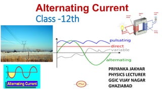
  • 1. Alternating Current Class -12th PRIYANKA JAKHAR PHYSICS LECTURER GGIC VIJAY NAGAR GHAZIABAD
  • 2. Alternating Current--Alternating current (AC) electricity is the type of electricity commonly used in homes and businesses throughout the world. While direct current (DC) electricity flows in one direction through a wire. AC electricity alternates its direction in a back-and-forth motion. •Alternating current is defined as the current that varies like a sine function with time. •The value of current will oscillate between a maximum value and a minimum value. •In case of AC the current is changing its magnitude at every instant of time. •The direction of current will be clockwise and anticlockwise and it will keep on repeating. ASymbol: C created by an electronic circuitry, allowing for a wide range of applications
  • 3. An electric current whose magnitude changes continuously with time and changes its direction periodically, is called an alternating current. The instantaneous value of alternating current at any instant of time t is given by I = Im sin ωt Where Im = maximum or peak value of the AC . •Alternating voltage is expressed as: - V = Vm sinωt •Where Vm = peak value of the voltage. •Advantages of AC 1) Easily stepped up or stepped down using transformer 2) Can be regulated using choke coil without loss of energy 3) Easily converted in to dc using rectifier (Pn - diode) 4) Can be transmitted over distant places 5) Production of ac is more economical created by an AC electric generator, which determines the frequency the voltage can be readily changed, thus making it more suitable for long-distance transmission than DC electricity can employ capacitors and inductors in electronic circuitry, allowing for a wide range of applications E, I – Instantaneous value of emf and current E0, I0 – Peak or maximum value or amplitude of emf and current ω – Angular frequency t – Instantaneous time ωt – Phase
  • 4. :angular frequency OR angular velocity t : time I0 :peak current V0 : peak voltage (  2f ) I  I sin t V V sin t o o T  1 f
  • 5. 1.Instantaneous value: It is the value of alternating current and voltage at an instant t. 2.Peak value: Maximum values of voltage E0 and current I0 in a cycle are called peak values 3.Mean or average value of a.c.: It is defined as that value of direct current which sends the same charge in a circuit in the same time as is sent by the given alternating current in its half time period. 4.Root – mean- square (rms) or effective or virtual value of a.c.: It is defined as that value of direct current which produces the same heating effect in a given resistor as is produced by the given alternating current when passed for the same time 5.Phase difference Between the EMF (Voltage) and the Current in an AC Circuit: A diagram that represents alternating current and voltage of the same frequency as rotating vectors (phasors) alogwith proper phase angle between them is called a phasor diagram. 6.Phase : It is that property of wave motion which tells us the position of the particle at any instant as well as its direction of motion. It is measured either by the angle which the particle makes with the mean position or by fraction of time period. 7.Phase angle : Angle associated with the wave motion (sine or cosine) is called phase angle. If Io is the peak value of alternating current and Iavg is the average value of current, then Io and Iavg are related as, Iavg = 0.637 Io
  • 6. 9. Lead : Out of the current and emf the one having greater phase angle will lead the other e.g., in equation i = i0 sin ωt + 𝝅 𝟐 and e = e0 sin ωt, the current leads the emf by an angle . 10. Lag : Out of current and emf the one having smaller phase angle will lag the other. In the above equations, the emf lags the current by.
  • 7. Phasor diagrams--A phasor is a straight line drawn in such a way that its length is related to the amplitude of the sine wave represented, and its angular position relative to other phasors is related to the phase difference between the quantities. The phasor represented by the arrow is rotating in an anticlockwise direction about the centre. Phasor diagrams •Phasor diagrams are the representations of voltage-current relationship in AC circuits. •A phasor is a vector capable of rotating about the origin with (angular velocity) ‘ω’. •The vertical component of phasor will represent the sinusoidally varying quantity. •Considering V = Vm sinωt then the vertical component represents the instantaneous value of voltage. •The magnitude(length of the vector) of the phasor is the peak value at that instant of time. •In certain circuits when current reaches its maximum value after emf becomes maximum then current is said to lag behind emf •When current reaches its maximum value before emf reaches its maximum then current is said to lead the emf Advantages of phasor diagram:- It is not possible to represent the complicated relationship between the voltage and currents with the help of graphs . In that case phasor diagrams are used.
  • 8. Five Rules for Drawing Phasor Diagrams. Rule 1. The length of the phasor is directly proportional to the amplitude of the wave depicted. Rule 2. In circuits which have combinations of L, C & R in SERIES it is customary to draw the phasor representing CURRENT horizontally, and call this the REFERENCE phasor. This is because the current in a series circuit is common to all the components. Rule 3. In parallel circuits, where L, C and R are connected in parallel .The phasor representing the SUPPLY VOLTAGE is always drawn in the REFERENCE direction. This is because in a parallel circuit it is the supply voltage that is common to all components. Rule 4. The direction of rotation of all phasors is considered to be ANTICLOCKWISE. Rule 5. In any one diagram, the same type of value (RMS, peak etc.) is used for all phasors, not a mixture of values.
  • 9.
  • 10. phase relationship between voltage and current, learn this simple word called ‘CIVIL’, i.e in capacitor current leads voltage and voltage leads current in inductor. C I V I L capacitor current voltage current inductor R E = E0 sin ωt R E = E0 sin ωt E = E0 sin ωt L E = E0 sin ωt C
  • 11. •When an alternating current passed through a moving coil galvanometer it shows no deflection ,this is because for one complete cycle mean value of alternating current is zero as AC flows in one direction during one half cycle and in opposite direction during another half cycle. •But mean value of A.C is finite over half cycle. •So, mean or average value of AC is defined either for positive half cycle or for negative half cycle •During next half cycle mean value of ac will be equal in magnitude but opposite in direction. •Always remember that mean value of AC over a complete cycle is zero and is defined over a half cycle of AC Average Value (or Mean Value) of Alternating Current The Average value or mean value of alternating current over any half cycle is defined as that value of steady current which would sent the same amount of charge through a circuit in the time of half cycle as is sent by the AC through the same circuit, in the same time. If Io is the peak value of alternating current and Iavg is the average value of current, then Io and Iavg are related as, Iavg = 0.637 Io Average Value (or Mean Value) of Alternating Voltage Average value or mean value of alternating e.m.f. over a half cycle is that value of constant e.m.f. which should same amount of charge through a circuit in the time of half cycle, as is sent by alternating e.m.f. through the same circuit in the same time. If Vo is the peak value of alternating e.m.f. and Vavg is the average value of e.m.f., then Vo and Vavg are related as, Vavg = 0.637 Vo
  • 12. dq = I dt = I0 sin ωt dt q = ∫ I0 sin ωt dt 0 T/2 q = 2 I0 / ω = 2 I0 T / 2π = I0 T / π Mean Value of AC, Im = Iav = q / (T/2) Average or Mean Value of Alternating emf: Note: Average or Mean value of alternating current or emf is zero over a cycle as the + ve and – ve values get cancelled. Em = Eav = 2 E0 / π = 0.637 E0 = 63.7 % E0 Im = Iav = 2 I0 / π = 0.637 I0 = 63.7 % I0
  • 13. Root Mean Square value of Alternating Voltage The root mean square value of alternating e.m.f. is defined as that value of steady voltage; which would generate the same amount of heat in a given resistance in a given time, as is done by the alternating e.m.f., when applied to the same resistance for the same time. Root mean square value of alternating current (Vrms) and maximum value of alternating current (Vo) are related as, Vrms = 0.707 Vo Root Mean Square value of Alternating Current Root mean square value of alternating current is defined as that value of steady current, which would generate the same amount of heat in a given time, as is done by the AC, when passed through the same resistance for the same time. Root mean square value of alternating current (Irms) and maximum value of alternating current (Io) are related as, Irms = 0.707 Io RMS value of a.c. The rms value of alternating current is defined as that value of the steady current, which when passed through a resistor for a given time, will generate the same amount of heat as generated by an alternating current when passed through the same resistor for the same time. The rms value is also called effective value of an a.c. and is denoted by Irms when an alternating current i=Iosin ωt flows through a resistor of resistance R, the amount of heat produced in the resistor in a small time dt is dH = 𝒊𝟐 R dt. We know that alternating current is given I = Iosinωt The total amount of heat produced in the resistance in one complete cycle is
  • 14. H = 𝟎 𝑻 𝒊𝟐 R dt 𝐻 = 𝟎 𝑻 𝒊𝟎 𝟐 𝒔𝒊𝒏𝟐 ߱‫ݐܴ݀ݐ‬ 𝐻 = 𝒊𝟎 𝟐 ܴ 𝟎 𝑻 ( 𝟏 − 𝒄𝒐𝒔𝟐𝝎𝒕 ) 𝟐 ݀‫ݐ‬ 𝐻 = 𝒊𝟎 𝟐 ܴ 𝟐 [ 𝟎 𝑻 ݀‫ݐ‬ − 𝟎 𝑻 ( 𝒄𝒐𝒔𝟐𝝎𝒕 ) dt ] 𝟎 𝑻 ( 𝒄𝒐𝒔𝟐𝝎𝒕 ) dt = 0 𝐻 = 𝒊𝟎 𝟐 ܴ 𝟐 T But this heat is also equal to the heat produced by rms value of AC in the same resistor (R) and in the same time (T), 𝐻 = 𝒊𝒓𝒎𝒔 𝟐 ܴ𝑇 Thus 𝒊𝒓𝒎𝒔 𝟐 ܴ𝑇 = 𝒊𝟎 𝟐 ܴ 𝟐 T Irms = Ieff = 𝒊𝟎 √2 = 0.707 I0 = 70.7 % I0 Root Mean Square or Virtual or Effective Value of Alternating emf: Erms = Eeff = E0 / √2 = 0.707 E0 = 70.7 % E0 Note:1. Root Mean Square value of alternating current or emf can be calculated over any period of the cycle since it is based on the heat energy produced. 2. Do not use the above formulae if the time interval under the consideration is less than one period.
  • 15. powerdc  average powerac I 2 R  I 2 ave R I  I ave  Irms The r.m.s (root mean square) current means the square root of the average value of the current
  • 16. Direct Current Alternating Current 1.Electron flow in one direction. 1.Electron flows in both directions. 2.Magnitude remains constant. 2.Magnitude varies with time. 3.Can be stored in batteries. 3.Cannot be stored. 4.E.g. batteries 4.AC generators & mains Comparison between AC and DC
  • 17. ADVANTAGES OF A.C. OVER D.C. •The generation of A.C. is cheaper than that of D.C. •Alternating voltage can be easily stepped up or stepped down by using a transformer. •A.C. can be easily converted into D.C. by rectifier. D.C. is converted to A.C. by an inverter. •A.C. can be transmitted to a long distance without appreciable loss.
  • 18. Resistor: Resistors are denoted by the letter “R”. A resistor is an element that dissipates energy mostly in form of heat. It will have a Voltage drop across it which remains fixed for a fixed value of current flowing through it. Capacitor: Capacitors are denoted by the letter “C”. A capacitor is an element which stores energy (temporarily) in form of electric field. Capacitor resists changes in voltage. There are many types of capacitors, out of which the ceramic capacitor and the electrolytic capacitors are mostly used. They charge in one direction and discharge in opposite direction Inductor: Inductors are denoted by the letter “L”. A Inductor is also similar to capacitor, it also stores energy but is stored in form of magnetic field. Inductors resist changes current. Inductors are normally a coil wound wire and is rarely used compared to the former two components.
  • 19. Reactance The opposition offered by an inductor or by a capacitor in the path of flow of alternating current is called reactance. Reactance is of two types (i) Inductive Reactance (XL)-- Inductive reactance is the resistance offered by an inductor. Inductive reactance (XL) = Lω = L2πf = L2π / T Its unit is ohm. XL ∝ f For direct current, XL = 0 (f = 0 (ii) Capacitive Reactance (Xc)-- Capacitive reactance is the resistance offered by an inductor Capacitive reactance, Xc = 1 / Cω = 1 / C2πf = T / C 2π Its unit is ohm Xc ∝ 1 / fsss For direct current, Xc = ∞ (f = 0)
  • 20. Impedance The opposition offered by an AC circuit containing more than one out of three components L, C and R, is called impedance (Z) of the circuit. Impedance of an AC circuit, Z = √R2 + (XL – XC)2 Its SI unit is ohm. Power in an AC Circuit The power is defined as the rate at which work is being in the circuit. The average power in an AC circuit, Pav = Vrms irms cos θ = V / √2 i / √2 cos θ = Vi / √2 cos θ where, cos θ = Resistance(R) / Impedance (Z) is called the power factor 0f AC circuit. Current and Potential Relations Here, we will discuss current and potential relations for different AC circuits.
  • 21. (i) Pure Resistive Circuit (R circuit) -- AC Circuit containing Resistor only When an AC is passed through a circuit containing (ideal) resistor only, then, alternating current and alternating e.m.f. are in phase and V = IR When only resistance is in an ac circuit Consider a simple ac circuit consisting of resistor of resistance R and and ac generator, According to Kirchhoff’s loop law at any instant , the algebraic sum of the potential difference around a closed loop in a circuit must be zero E –𝑽𝑹 = 0 E –IR = 0 E0 sinωt – IR = 0 I = Eo sin ωt R -----1 Io sin ωt = Eo sin ωt R Io = Eo R t 0 π 2π 3π 4π π/2 3π/2 5π/2 7π/2 θ = ωt E0 I0 E = E0 sin ωt I = I0 sin ωt E0 I0 ωt y x 0 E ,I R E = E0 sin ωt T/4 T/2 3T/4 T 5T/4 3T/2 7T/4 2T E0 I0 ωt x 0 R E = E0 sin ωt
  • 22. Where Io is the maximum current Io = Eo /R From above equations, we see that the instantaneous voltage drop across the resistor is V = Io R sinωt ---(2) We see in equation (1) and (2) I and V both vary as sinωt and reach their maximum values at the same time as shown in graph they are said to be in phase. (a) Alternating emf, E = Eo sin ωt (b) Alternating current, I = Io sin ωt (c) Alternating emf and alternating current both are in the same phase. (d) Average power decay, (P) = Ev . Iv (e) Power factor, cos θ = 1
  • 23. AC Circuit with a Pure Inductor: When AC is passed through a circuit containing (ideal) inductor only, then, alternating current lags behind alternating e.m.f. by a phase angle of π/2. It represents the effective opposition of the coil to the flow of alternating current. It is denoted by XL. XL= ωL = 2 π f L Inductive reactance increases with increase in frequency i.e., XL ∝ f According to Kirchhoff’s loop law at any instant , the algebraic sum of the potential difference around a closed loop in a circuit must be zero E –𝑽𝑳 = 0 Induced emf in the inductor is - L dI dt sIn order to maintain the flow of current, the applied emf must be equal and opposite to the induced emf. E = E0 sin ωt L XL f 0
  • 24. T/4 T/2 3T/4 T 5T/4 3T/2 7T/4 2T t E ,I E = E0 sin ωt I = I0 sin (ωt - π / 2) I = ∫ ( E0 L ) sin ωt dt I = ( E0 ωL )( - cos ωt ) I = I0 sin (ωt - π / 2) (where I0 = ( E0 ωL )and XL = ωL = E0 I0 ) XL is Inductive Reactance. Its SI unit is ohm. I0 Current lags behind emf by π/2 rad. 0 π 2π 3π 4π π/2 3π/2 5π/2 7π/2 θ = ωt E0 E = L dI dt E0 sin ωt = L dI dt dI = ( E0 L )sin ωt dt y (a) Alternating emf, E = Eo sin ωt (b) Alternating current, I = Io sin (ωt – π / 2) (c) Alternating current lags behind alternating emf by π / 2. (d) Inductive reactance, XL = Lω = L2πf (e) Average power decay, (P) = 0 (f) Power factor, cos θ = cos 90° = 0 x 0 x E0 ωt π/2 I0 E = L dI dt E0 sin ωt = L dI dt
  • 25. (iii) Pure Capacitive CircuitWhen AC is passed through a circuit containing (ideal) capacitor only then, alternating current leads lead alternating voltage by a phase angle of 90o. Capacitance (C) allows AC to flow through it but blocks DC.s Inductive capacitance: Effective opposition of the capacitor to the flow of alternating current is known as capacitive reactance. It is denoted by XC XC = 𝟏 𝝎 𝑪 = 𝟏 2 π f 𝑪 Inductive capacitance decreases with increase in frequency i.e., Xc ∝ 𝟏 f On applying Kirchhoff’s rule to this circuit, we get E –𝑽𝑪 = 0 𝑽𝑪 = E 𝑽𝑪 = Eo sin ωt Where 𝑽𝑪 is the instantaneous voltage drop across the capacitor. From the definition of capacitance 𝑽𝑪 = q/C, and this value of 𝑽𝑪 substituted into equation gives (a) Alternating emf, E = Eo sin ωt (b) Alternating current, I = Io sin (ωt + π / 2) (c) Alternating current leads alternating emf by π / 2. (d) Inductive reactance, Xc = 𝟏 𝝎 𝑪 = 𝟏 2 π f 𝑪 (e) Average power decay, (P) = 0 E = E0 sin ωt C E = E0 sin ωt q = CE = CE0 sin ωt q = C Eo sin ωt
  • 26. y E0 ωt (where I0 = E0 / (1 / ωC) and XC = 𝟏 ω𝑪 = E0 I0 XC is Capacitive Reactance. Its SI unit is ohm. I0 π/2 x 0 Current leads the emf by π/2 radians. T/4 T/2 3T/4 T 5T/4 3T/2 7T/4 2T t 0 π 2π 3π 4π π/2 3π/2 5π/2 7π/2 θ = ωt E ,I E0 I0 E = E0 sin ωt I = I0 sin (ωt + π / 2) Charging and Discharging of a Capacitor When the capacitor is connected to an ac source, it limits or regulates the current, but does not completely prevent the flow of charge. The capacitor is alternately charged and discharged as the current reverses each half cycle. I = dq dt = d dt [CE0 sin ωt] I = [E0 / ( 𝟏 ω𝑪 )] ( cos ωt ) I = I0 sin (ωt + π / 2) XC f 0 Xc ∝ 𝟏 f
  • 27. (iv) R – C Circuit SERIES R-C Circuit Now consider an ac circuit consisting of resistance R and a capacitor of capacitance C in series with an ac source generator E = Eo sin ωt I = Eo / 2 sin (ωt – φ) Z = √R2 + (1 / ωC)2 tan φ = – 1 / ωC / R Current leading the voltage by φ V2 = V2 R - V2 C Suppose in phasor diagram, current is taken along positive direction. The 𝑽𝑹 is also along positive x-direction as there is no phase difference between 𝒊𝑹 and 𝑽𝑹 . While 𝑽𝑳will be along y direction as we know that current lags behind the voltage by 𝟗𝟎𝑶 V = 𝑽𝑹 + 𝑽𝑳 = iR + (i 𝑿𝑪 ) V = I Z Here Z = R + j 𝑿𝑪 = R + (1/߱𝑪) is called as impedance of the circuit. Impedance plays the same role in ac circuit as the ohmic resistance does in DC circuit. The modulus of impedance is |𝑍| = √𝑹𝟐 + (߱‫)ܮ‬ 𝟐 The potential difference leads the current by an angle R E = E0 sin ωt C x 0 𝑽𝑪 𝜑 𝑽𝑹
  • 28. 𝜑 = ‫𝑛𝑎ݐ‬−1 | 𝑽𝑪 𝑽𝑹 | = ‫𝑛𝑎ݐ‬−1 ( 𝑿𝑪 ܴ ) 𝜑 = ‫𝑛𝑎ݐ‬−1 ( 1/߱𝑪 ܴ ) = ‫𝑛𝑎ݐ‬−1 ( 1/𝟐𝝅𝒇𝑪 ܴ ) i)If L = 0 then tan 𝜑 =0 or 𝜑 = 𝟎𝑶 Voltage and current are in same phase because circuit will be purely resistive in nature . ii)If R = 0 then tan 𝜑 =∞ or 𝜑 = 𝟗𝟎𝑶 In this condition voltage will lead over the current by 90 degree because circuit will be purely inductive in nature.
  • 29. L-R Circuit Now consider an ac circuit consisting of a resistor or resistance R and an inductor of inductance L in series with an ac source generator Suppose in phasor diagram, current is taken along positive direction. The 𝑽𝑹 is also along positive x-direction as there is no phase difference between 𝒊𝑹 and 𝑽𝑹 . While 𝑽𝑳will be along y direction as we know that current lags behind the voltage by 𝟗𝟎𝑶 V = 𝑽𝑹 + 𝑽𝑳 = iR + (i 𝑿𝑳 ) V= iZ Here Z = R + j𝑿𝑳 = R + (ωL) is called as impedance of the circuit. Impedance plays the same role in ac circuit as the ohmic resistance does in DC circuit. The modulus of impedance is |𝑍| = √𝑹𝟐 + (߱‫)ܮ‬𝟐 The potential difference leads the current by an angle 𝜑 = ‫𝑛𝑎ݐ‬−1 | 𝑽𝑳 𝑽𝑹 | = ‫𝑛𝑎ݐ‬−1 ( 𝑿𝑳 ܴ ) 𝜑 = ‫𝑛𝑎ݐ‬−1 ( ߱‫ܮ‬ ܴ ) =‫𝑛𝑎ݐ‬−1 ( 2𝛑𝒇‫ܮ‬ ܴ ) V x 0 R E = E0 sin ωt L 𝑽𝑳 𝑽𝑹 𝜑 i)If L = 0 then tan 𝜑 =0 or 𝜑 = 𝟎𝑶 Voltage and current are in same phase because circuit will be purely resistive in nature . ii)If R = 0 then tan 𝜑 =∞ or 𝜑 = 𝟗𝟎𝑶 In this condition voltage will lead over the current by 90 degree because circuit will be purely inductive in nature.
  • 30. AC Circuit with L, C, R in Series Combination Consider an ac circuit consisting of resistance R, capacitor of capacitance C and an inductor of inductance L are in series with ac source generator Suppose in a phasor diagram current is taken along positive x-direction. Then VR is along positive x-direction, VL along positive y-direction and VC along negative y-direction, as potential difference across an inductor leads the current by 90 in phase while that across a capacitor, lags by 90 For a series LCR circuit driven by voltage V = Vm sin ω t, the current is given by I = Im sin (ω t ‒ ϕ). Here we make an assumption that XL > XC Above relation is graphically shown in the figure given below Here, e.m.f. is leading the current by phase angle ϕ and Z is called impedance of the circuit and is measure in ohm. E = E0 sin ωt C L R VR I π/2 π/2 - VC VL VR I π/2 0 VC VL VC VL VR I VL
  • 31. E = E0 sin ωt C L R 1) In R, current and voltage are in phase. 2) In L, current lags behind voltage by π/2 3) In C, current leads the voltage by π/2 VL - VC VR I E Φ E = √ [VR 2 + (VL – VC)2] The applied emf appears as Voltage drops VR, VL and VC across R, L and C respectively. E = √ [VR 2 + (VL – VC)2] Ohms law current = 𝒗𝒐𝒍𝒕𝒂𝒈𝒆 𝒓𝒆𝒔𝒊𝒔𝒕𝒂𝒏𝒄𝒆 I = E √ [R2 + (XL – XC)2] Z = √ [R2 + (XL – XC)2] Z = √ [R2 + (ω L – 𝟏 𝝎 𝑪 ) 2] tan Φ = XL – XC R tan Φ = (ω L – 𝟏 𝝎 𝑪 ) R or VR I π/2 π/2 - VC VL VR I π/2 0 VC VL VC VL VR I VL VR = iR VL = i XL VC = i XC
  • 32. or tan Φ = XL – XC R tan Φ = ω L – 1/ωC R Special Cases: Case I: When XL > XC i.e. ω L > 1/ωC, tan Φ = +ve or Φ is +ve The current lags behind the voltage or emf by phase angle Φ and the LCR circuit is inductance - dominated circuit. Case II: When VL < VC then XL < XC i.e. ω L < 1/ωC, tan Φ = -ve or Φ is –ve The current leads the voltage or emf by phase angle Φ and the LCR circuit is capacitance - dominated circuit. Case III: When VL = VC then XL = XC i.e. ω L = 1/ωC, tan Φ = 0 or Φ is 0° The current and the voltage or emf are in same phase. The impedance does not depend on the frequency of the applied emf. LCR circuit behaves like a purely resistive circuit. The root mean square voltage (Vrms) cannot be added arithmetically to the applied root mean square voltage, i.e., Vrms ≠ VL + VC + VR 𝜑 = ‫𝑛𝑎ݐ‬−1 (VL − VC )/VR 𝜑 = ‫𝑛𝑎ݐ‬−1 ( XL − XC )/ܴ 𝜑 = ‫𝑛𝑎ݐ‬−1 ( ߱‫ܮ‬ − 1 /߱𝐶 )/ܴ
  • 33. SERIES L – C – R The steady current is given by The peak current is It depends on angular frequency ω of ac source and it will be maximum when I = V0 √ [R2 + (XL – XC)2] 𝑠𝑖𝑛(߱‫ݐ‬ + 𝜑) I = V0 √ [R2 + (ω L – 𝟏 𝝎 𝑪 ) 2] 𝑠𝑖𝑛(߱‫ݐ‬ + 𝜑) I0 = V0 √ [R2 + (ω L – 𝟏 𝝎 𝑪 ) 2]
  • 34. (ω L – 𝟏 𝝎 𝑪 ) = 0 ߱ = √ 𝟏 𝑳 𝑪 And corresponding frequency is 𝑓 = ߱ 2ߨ = 1 2ߨ √ 𝟏 𝑳 𝑪 This frequency is known as resonant frequency of the given circuit. At this frequency peak current will be 𝑰𝟎 = 𝑽𝟎 𝑹 This resistance R in the LCR circuit is zero, the peak current at resonance is 𝑰𝟎 = 𝑽𝟎 𝑹 It means, there can be a finite current in pure LC circuit even without any applied emf. When a charged capacitor is connected to pure inductor This current in the circuit is at frequency 𝑓 = 1 2ߨ √ 𝟏 𝑳 𝑪
  • 35. L – C – R Circuit (a) Alternating emf, E = Eo sin Ωt (b) Alternating current, I = Io sin (Ωt ± θ) (c) Alternating current lags leads behind alternating emf by ω. (d) Resultant voltage, V = √V2 R + (VL – VC)2 (e) Impedance, Z = √R2 + (XL – XC)2 (f) Power factor, cos θ = R / Z = R / √√R2 + (XL – XC)2 (g) Average power decay, (P)= EVIV cos θ
  • 36. Power in AC Circuit with L, C, R: Instantaneous Power = E I = E0 I0 sin ωt sin (ωt + Φ) = E0 I0 [sin2 ωt cosΦ + sin ωt cosωt cosΦ] E = E0 sin ωt I = I0 sin (ωt + Φ) (where Φ is the phase angle between emf and current) If the instantaneous power is assumed to be constant for an infinitesimally small time dt, then the work done is dW = E0 I0 [sin2 ωt cosΦ + sin ωt cosωt cosΦ] Work done over a complete cycle is W = ∫ E0 I0 [sin2 ωt cosΦ + sin ωt cosωt cosΦ] dt 0 T W = E0I0 cos Φ x 𝑻 𝟐 Average Power over a cycle is Pav = W / T Pav = ( E0 I0 𝟐 ) cos Φ Pav = ( E0 √𝟐 I0 √𝟐 ) cos Φ (where cos Φ = 𝑹 𝒁 = R /√ [R2 + (ω L – 𝟏 𝝎 𝑪 ) 2] is called Power Factor) Pav = Ev Iv cos Φ In case of steady current the rate of doing work is given by, P = VI In an alternating circuit, current and voltage both vary with time, so the work done by the source in time interval dt is given by dW = VI dt Suppose in an ac, the current is leading the voltage by an angle φ . Then we can write
  • 37. Ev Power in AC Circuit with R: In R, current and emf are in phase. Φ = 0° Pav = Ev Iv cos Φ = Ev Iv cos 0° = Ev Iv Power in AC Circuit with L: In L, current lags behind emf by π/2. Φ = - π/2 Pav = Ev Iv cos (-π/2) = Ev Iv (0) = 0 Power in AC Circuit with C: In C, current leads emf by π/2. Φ = + π/2 Pav = Ev Iv cos (π/2) = Ev Iv (0) = 0 Note: Power (Energy) is not dissipated in Inductor and Capacitor and hence they find a lot of practical applications and in devices using alternating current. Pav = Ev Iv cos Φ Wattless Current or Idle Current: Iv Iv cos Φ Iv sin Φ Φ 90° The component Iv cos Φ generates power with Ev. However, the component Iv sin Φ does not contribute to power along Ev and hence power generated is zero. This component of current is called wattless or idle current. P = Ev Iv sin Φ cos 90° = 0
  • 38. Apply (i) average power, (ii)instantaneous power, (iii)power factor, in AC circuit consisting of R, RC, RL and RCL in series. P  IV cos  Pr  Pav Pa IV  IrmsVrms cos Pav • Power factor is a way of measuring how efficiently electrical power is being used within a facility's electrical system 𝑃 = Vrms Irms 𝑐𝑜𝑠𝜑 This can also be written as, Here P = I2 Z cosφ Z is impedance, the term cosφ is known as power factor where cos  is called the power factor of the AC circuit, Pr is the average real power and I2Z is called the apparent power
  • 39. • In an ac circuit , the power is only dissipated by a resistance, none is dissipated by inductance or capacitance • From the phasor diagram of the RCL series circuit ω VL V VL VC  • Then V V V cos We get cos  R Pav  IV cos and V  IZ Pav  I 2 Z cos  Pr R V V  I C
  • 40. • Power factor is defined as • From • the power factor also can be calculated by using the equation VR IR V IZ  below cos  Z cos  R 2 L C V  I R2  X  X • When  = 0o (cos  =+1) ,the circuit is completely resistive or when the circuit is in resonance (RCL) • When  = +90o (cos  = 0), the circuit is completely inductive • When  = -90o (cos  =0), the circuit is completely capacitive Pa I 2 Z Pr  Pr cos 
  • 41. Resonance in AC Circuit with L, C, R: When XL = XC i.e. ω L = 1/ωC, tan Φ = 0 or Φ is 0° and Z = √ [R2 + (ω L – 1/ωC)2] becomes Zmin = R and I0max = E / R i.e. The impedance offered by the circuit is minimum and the current is maximum. This condition is called resonant condition of LCR circuit and the frequency is called resonant frequency. At resonant angular frequency ωr , ωr L = 1/ωrC or ωr = 1 / √LC or fr = 1 / (2π √LC) ωr I0max ω 0 R1 R2 R3 I0 I0max / √2 ωr - ∆ ω ωr + ∆ ω Band width = 2 ∆ ω Quality factor (Q – factor) is defined as the ratio of resonant frequency to band width. Q = ωr / 2 ∆ ω or Q = ωr L / R or Q = 1 / ωrCR Q = VL / VR or Q = VC / VR Resonant Curve & Q - Factor: It can also be defined as the ratio of potential drop across either the inductance or the capacitance to the potential drop across the resistance. R1 < R2 < R3 Q-factor The selectivity or sharpness of a resonant circuit is measured by the quality factor or Q factor. In other words it refers to the sharpness of tuning at resonance.
  • 42. •Choke Coil: 1.An inductive coil used for controlling alternating current whose self- inductance is high and resistance negligible, is called choke coil. 2.The power factor of this coil is approximately zero. 3.It controls current without consuming any power. •A choke coil is a pure inductor. Average power consumed per cycle is zero in a choke coil. •A DC motor connects DC energy from a battery into mechanical energy of rotation. •An AC dynamo/generator produces are energy from mechanical energy of rotation of a coil. •An induction coil generates high voltages of the order of 1OS V from a battery. It is based on the phenomenon of mutual induction.