This document provides an overview of the 80386DX processor. It discusses the course objectives which are to learn the architecture, instruction set, and assembly programming of the 80386DX. The outcomes include being able to develop small real-life embedded applications using assembly language and understanding the architecture thoroughly. It then covers what a microprocessor is and provides details on the architecture, features, and memory organization of the 80386DX, including its segmentation unit, paging unit, and support for protected and virtual modes.
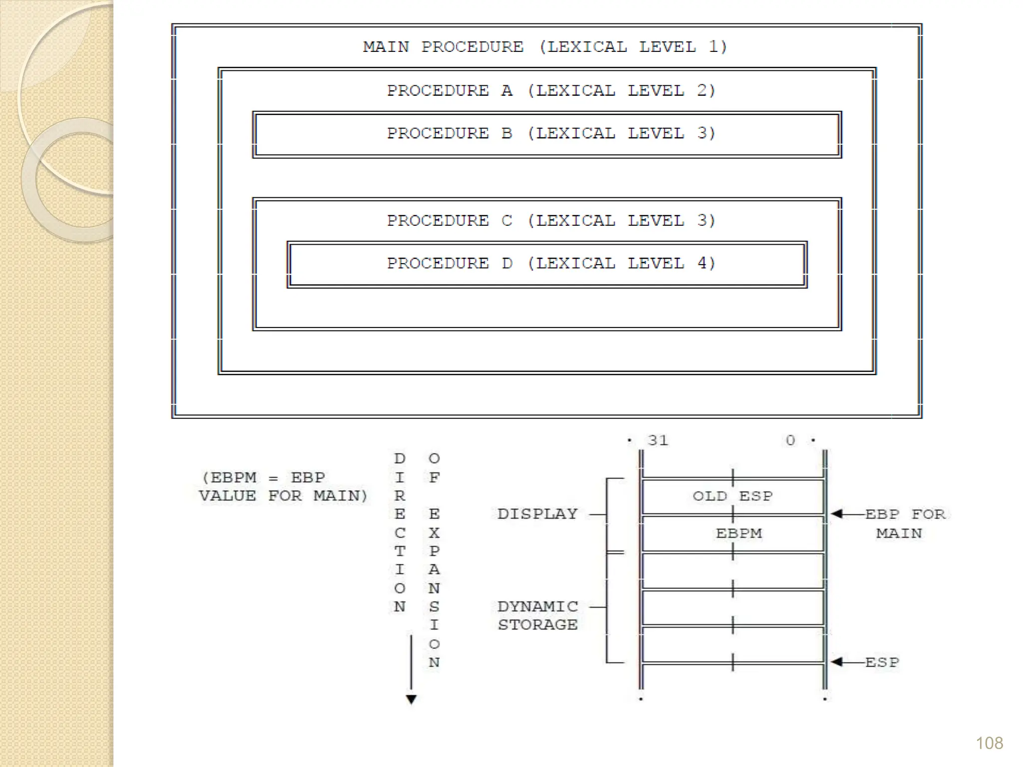
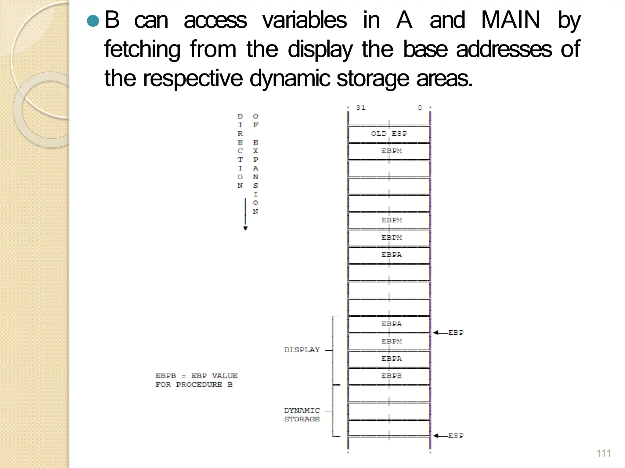
![⚫ Procedure A can access variables in MAIN since
MAIN is at level 1. Therefore the base for the
dynamic storage for MAIN is at [EBP-2].
⚫ All dynamic variables for MAIN are at a fixed
offset from this value.
110](https://image.slidesharecdn.com/mpunit-1se-ii-240228074356-d342acf6/75/Microprocessor-Unit-1-SE-computer-II-pptx-110-2048.jpg)