Mode 1 programming
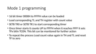
•16 bit timer 0000H to FFFFH value can be loaded
• Load corresponding TL and TH register with count value
• SETB TR0 or SETB TR1 to start corresponding timer
• Once timer starts it counts UP to FFFFH when it reaches FFFF it sets
TFx bitin TCON. This bit can be monitored for further action
• To repeat the process Load count value again in TH and TL and reset
TF to zero
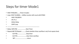
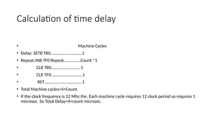
Calculation of timedelay
• Machine Cycles
• Delay: SETB TR0…………………………1
• Repeat:JNB TF0 Repeat…………….Count *1
• CLR TR0……………………….1
• CLR TF0…………………………1
• RET………………………………1
• Total Machine cycles=4+Count.
• If the clock frequency is 12 Mhz the. Each machine cycle requires 12 clock period so requires 1
microsec. So Total Delay=4+count microsec.
6.
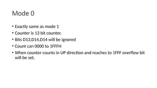
Mode 0
• Exactlysame as mode 1
• Counter is 13 bit counter.
• Bits D13,D14,D14 will be ignored
• Count can 0000 to 1FFFH
• When counter counts in UP direction and reaches to 1FFF overflow bit
will be set.
7.
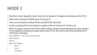
MODE 2
• 8bit timer mode. Repetitive mode. Count can be loaded in TH register only (between 00 to FF H)
• After Count is loaded in TH,8051 gives its copy to TL
• Timer can be started by setting TRx Bit using SETB TRx instruction
• It starts counting UP by incrementing TL register. When it reaches to FF TFx bit is set
• When TL register rolls over from FFH to 00H It will get reloaded automatically by the value stored in
TH. To repeat the counting we simply need to clear TF bit. (No need to start timer)Contents of TH
will remain unchanged.
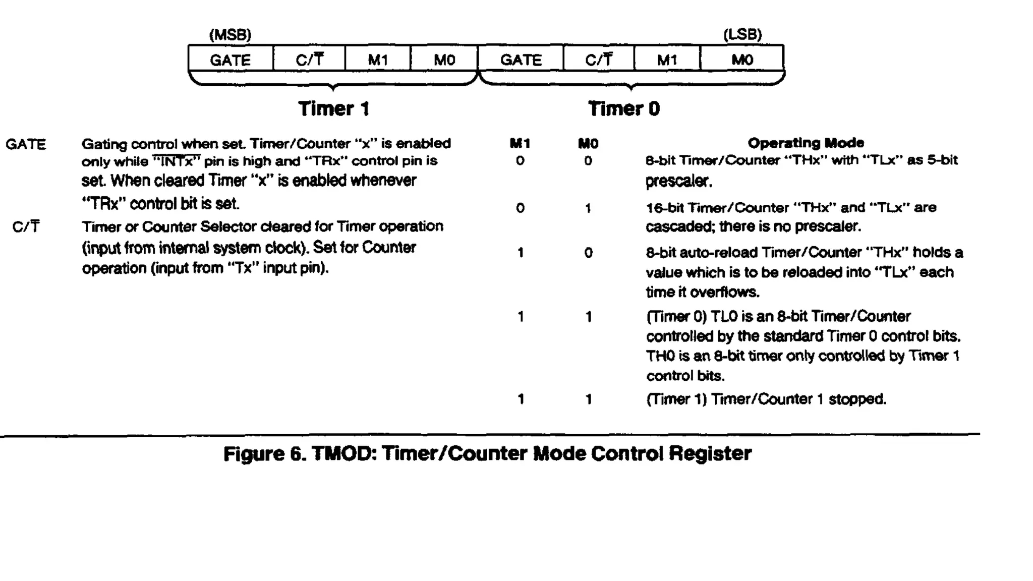
• MOV TMOD,#20H….. Timer 1 mode 2 8 bit auto reload
• MOV TH1,#count
• SETB TR1
• Repeat: JNB TF1,Repeat
• CPL P1.1
• CLR TF1
• SJMP Repeat
8.
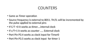
COUNTERS
• Same asTimer operation
• Source frequency is external to 8051. TH,TL will be incremented by
the pulse applied to external pins
• If C/T =0 it works as timer….internal clock
• If c/T=1 it works as counter ….. External clock
• Port Pin P3.4 works as clock input for Timer0
• Port Pin P3.5 works as clock input for timer 1
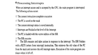
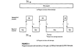
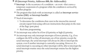
IP (InterruptPriority, Addresses B8h, Bit-Addressable):
Interrupt :Is the occurrence of a condition – an event –that causes a
temporary suspension of a program while the condition is serviced by
another program
The program that deals with an interrupt is called an Interrupt service
routine (ISR) or Interrupt handler
Need of interrupts :
o To determine the conditions that exist in the internal & external
circuits (apart from using software instructions that jump on the state
of the flags /port pins)
o Real time programming
An interrupt may either be of low (0) priority or high (1) priority.
An interrupt may only interrupt interrupts of lower priority. E.g., if we
configure the 8051 so that all interrupts are of low priority except the
serial interrupt, the serial interrupt will always be able to interrupt the
system, even if another interrupt is currently executing. However, if a
serial interrupt is executing no other interrupt will be able to interrupt the
serial interrupt routine since the serial interrupt routine has the highest
priority.
12.
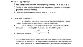
Timer Flaginterrupt :
A
a
Generated whenever timer roll over from all 1’s to all 0’s.
Serial port interrupt :
If a data byte is received from external circuit to serial buffer (SBUF)
register, an interrupt bit , RI, is set to 1 in the SCON register.
when data byte has been transmitted from serial buffer to outside
circuit, an interrupt bit TI, is set to 1 in the SCON register.
Serial port interrupt
Note that these bits aren’t cleared when the interrupt generated program call
is made by the processor . The program that handles serial data communication
MUST reset the RI or TI to 0 to enable the next data communication operation.
13.
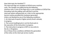
How Interrupts AreHandIed???
The interrupt flags are sampled at S5P2of every machine
cycle. The samples are polled during the following
machine cycle. If one of the flags was in a set condition at S5P2of the
Preceding cycle the polling cycle will find it and the
interrupt system will generate an L-CALL to the appropriate
Service routine,provided this hardware-generated
LCALLs not blocked by any of the following conditions:
1. An interrupt of equal or higher priority level is already
in progress.
2. The current (polling)cycle is not the final cycle in
the execution of the instruction in progress.
3. The instruction in progress is RETI or any write to
the IE or 1Pregisters.
Any of these three conditions will block the generation
of the LCALL to the interrupt service routine
14.
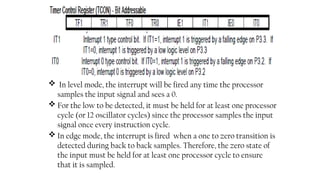
In levelmode, the interrupt will be fired any time the processor
samples the input signal and sees a 0.
For the low to be detected, it must be held for at least one processor
cycle (or 12 oscillator cycles) since the processor samples the input
signal once every instruction cycle.
In edge mode, the interrupt is fired when a one to zero transition is
detected during back to back samples. Therefore, the zero state of
the input must be held for at least one processor cycle to ensure
that it is sampled.
15.
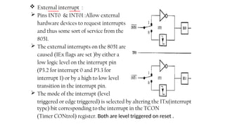
External interrupt:
Pins INT0 & INT01 :Allow external
hardware devices to request interrupts
and thus some sort of service from the
8051.
The external interrupts on the 8051 are
caused (IEx flags are set )by either a
low logic level on the interrupt pin
(P3.2 for interrupt 0 and P3.3 for
interrupt 1) or by a high to low level
transition in the interrupt pin.
The mode of the interrupt (level
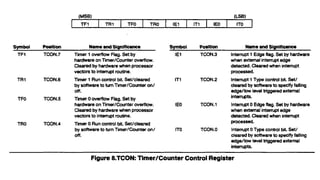
triggered or edge triggered) is selected by altering the ITx(interrupt
type) bit corresponding to the interrupt in the TCON
(Timer CONtrol) register. Both are level triggered on reset .
16.
Interrupt Latency :
The 8051 samples the interrupt flags once every processor cycle to
determine if any interrupts are pending.
An interrupt is requested by the appropriate signal being set for the
processor core to recognize in its next sampling period. Thus, the time
between an interrupt being requested and recognized by the processor
is one instruction cycle. At this point, the hardware will generate a call
to the interrupt service routine in the vector which takes two cycles.
Thus, the overall process takes three cycles total.
Under ideal conditions (where nothing is blocking the interrupt call)
and no instruction is in the works, an interrupt will be responded to in
three instruction cycles. This response time is excellent and provides
the user with very fast response time to system events.
There will inevitably be times that an interrupt is not responded to
within the three cycles discussed above. The most significant of these
is when an interrupt of equal or higher priority is being serviced. In
this case, the latency to service the pending interrupt depends entirely
on the ISR currently being executed.
17.
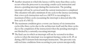
Another situationin which the latency will be more than three cycles
occurs when the processor is executing a multi-cycle instruction and
detects a pending interrupt during this instruction. The pending
interrupt will not be serviced until the current instruction is completed.
This situation will add a minimum of one cycle to the latency (assuming
that a two cycle instruction such as a MOVX is executing) to a
maximum of three cycles (assuming the interrupt is detected after the
first cycle of a MUL).
The maximum condition gives a worst case latency of six instruction
cycles (the three cycles due to the architecture itself and the three cycles
due to the completion of the instruction) when the pending interrupt is
not blocked by a currently executing interrupt.
The final case in which an interrupt will not be vectored to in three
cycles is when the interrupt was recognized during a write to IE, IP, or
during a RETI (return from interrupt) instruction. This prevents very
odd real time conditions from occurring in your system unexpectedly.
18.
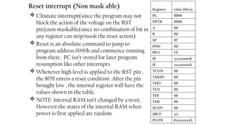
Reset interrupt (Nonmask able)
Ultimate interrupt(since the program may not
block the action of the voltage on the RST
pin),non maskable(since no combination of bit in
any register can stop/mask the reset action).
Reset is an absolute command to jump to
program address 0000h and commence running
from there . PC isn’t stored for later program
resumption like other interrupts
Whenever high level is applied to the RST pin ,
the 8051 enters a reset condition .After the pin
brought low , the internal register will have the
values shown in the table.
NOTE: Internal RAM isn’t changed by a reset.
However the states of the internal RAM when
power is first applied are random.
Register value (Hex)
PC 0000
DPTR 0000
A 00
B 00
SP 07
PSW 00
P0-3 FF
IP xxxooooob
IE oxxooooob
TCON 00
TMOD 00
THO 00
TLO 00
TH1 00
TH0 00
SCON 00
SBUF xx
PCON 0xxxxxxxb
19.
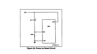
For 8051devices whenVCCis turned on an automatic
reset can be obtained by connecting the RST pin to
Vcc through a 10pF capacitor and to Vss through an
8.2 Kohm resistor. The CHMOS device do
not require this resistor although its presence does no
harm. In fact, for CHMOS devices the external resistor
can be removed because they have an internalpulldown
on the RSTpin. The capacitor value could then be reduced to
1 pF.
When poweris turned on, the circuit holds the RST pin
High for an amount of time that depends on the capacitor
Value and the rate at which it charges.To ensure a
valid reset the RST pin must be held high long enough
to allow the oscillator to start up plus two machine
cycles.
On power up, VCC should rise within approximately
ten milli seconds. The oscillator start-up time will depend on
the oscillator frequency. For a 10MHzcrystal,
the start-up time is typically1 ns. For a 1MHzcrystal,
the start-up time is typically 10ms.
With the given circuit reducing Vcc quickly to O causes
the RST pin voltage to momentarily fall below OV.
However, this voltageis internaly limited and will not
harm the device.
20.
NOTE:
The port pinswill be in a random state until
the oscillator has started and the internal reset
Algorithm has written 1s to them.
Powering up the device without a valid reset could
cause the CPU to start executing instructions from an
Indeterminate location. This is because the SFRs, specifically
the Program Counter, may not get properly
initialized.