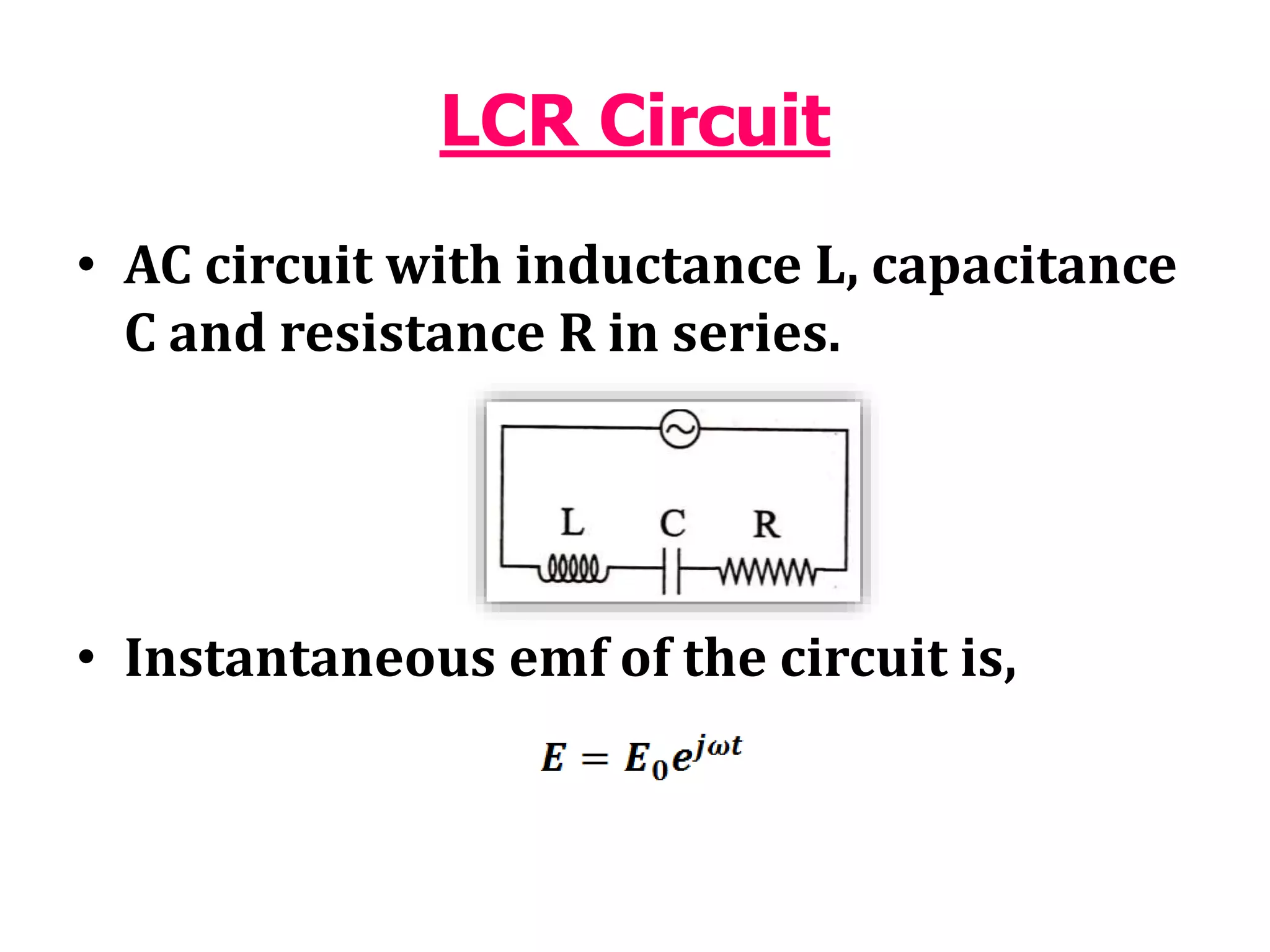
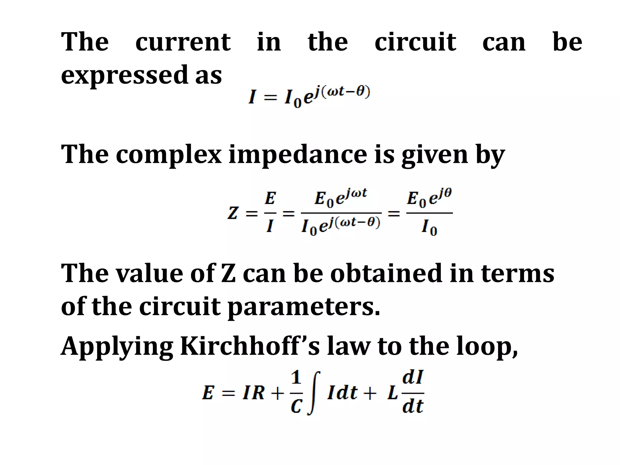
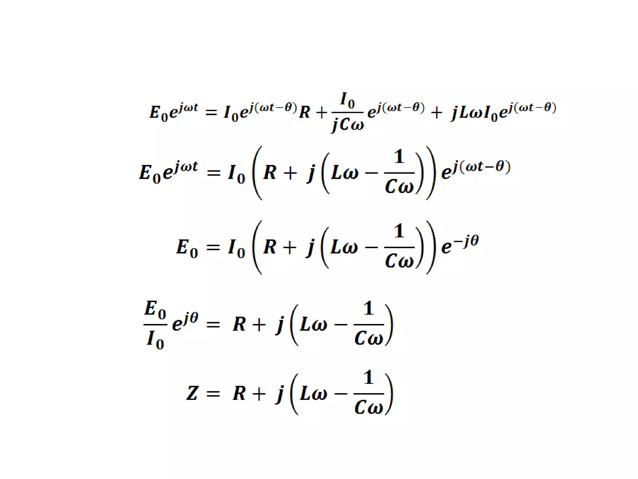
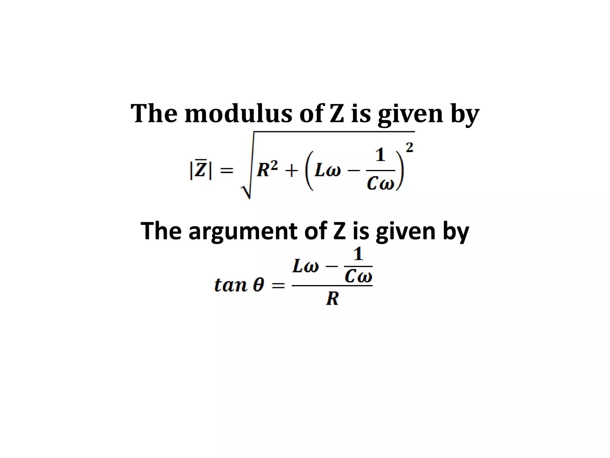
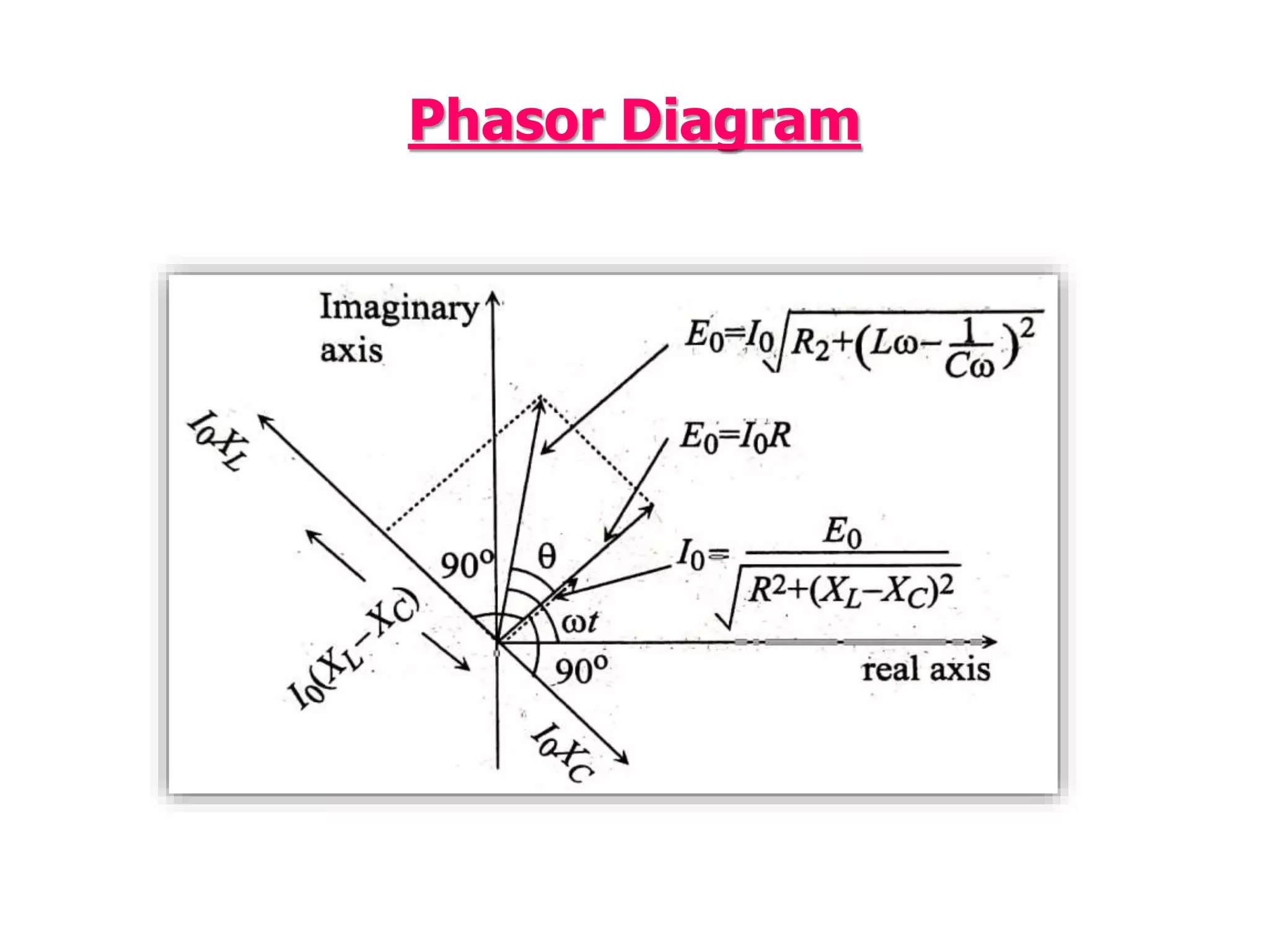
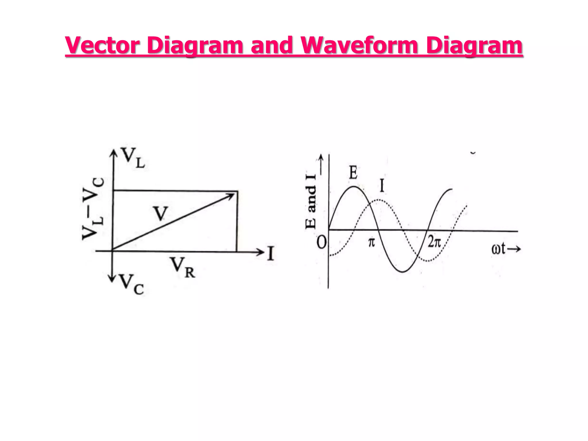
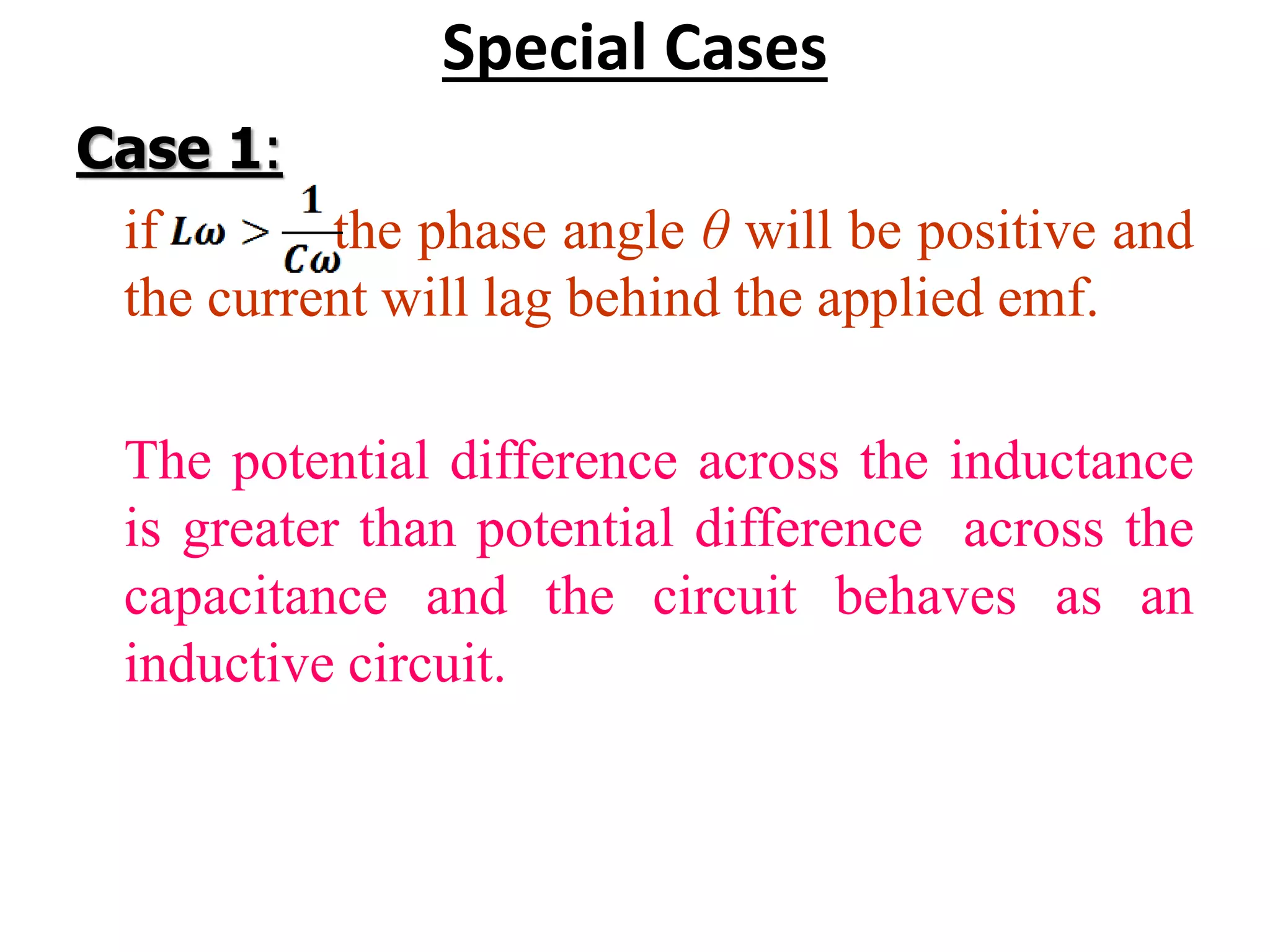
AC CIRCUIT WITH
INDUCTANCE, CAPACITANCE
AND RESISTANCE IN SERIES
Syam Kumar S U
Assistant Professor
Department of Physics
N.S.S. College, Nilamel
LCR Circuit
• AC circuit with inductance L, capacitance
C and resistance R in series.
• Instantaneous emf of the circuit is,
The current in the circuit can be
expressed as
The complex impedance is given by
The value of Z can be obtained in terms
of the circuit parameters.
Applying Kirchhoff’s law to the loop,
The modulus of Z is given by
The argument of Z is given by
Phasor Diagram
Vector Diagram and Waveform Diagram
Special Cases
Case 1:
if the phase angle θ will be positive and
the current will lag behind the applied emf.
The potential difference across the inductance
is greater than potential difference across the
capacitance and the circuit behaves as an
inductive circuit.
Case 2:
If the phase angle will be negative
and the current will lead the applied emf.
The circuit behaves as a capacitive circuit.
Case 3:
If the phase angle θ becomes zero.
The emf and current will be in phase.
The potential difference across the
inductance and capacitance are equal in
magnitude but opposite in direction and
hence cancel out.
It behaves as a purely resistive circuit.
Vector Diagram in the Complex Plane
• Under this condition the peak current will be
maximum and is given by
• The circuit is said to be a series resonance
circuit and the phenomenon is called
resonance.
LCR Circuit

LCR Circuit

  • 1.
    AC CIRCUIT WITH INDUCTANCE,CAPACITANCE AND RESISTANCE IN SERIES Syam Kumar S U Assistant Professor Department of Physics N.S.S. College, Nilamel
  • 2.
    LCR Circuit • ACcircuit with inductance L, capacitance C and resistance R in series. • Instantaneous emf of the circuit is,
  • 3.
    The current inthe circuit can be expressed as The complex impedance is given by The value of Z can be obtained in terms of the circuit parameters. Applying Kirchhoff’s law to the loop,
  • 5.
    The modulus ofZ is given by The argument of Z is given by
  • 6.
  • 7.
    Vector Diagram andWaveform Diagram
  • 8.
    Special Cases Case 1: ifthe phase angle θ will be positive and the current will lag behind the applied emf. The potential difference across the inductance is greater than potential difference across the capacitance and the circuit behaves as an inductive circuit.
  • 9.
    Case 2: If thephase angle will be negative and the current will lead the applied emf. The circuit behaves as a capacitive circuit.
  • 10.
    Case 3: If thephase angle θ becomes zero. The emf and current will be in phase. The potential difference across the inductance and capacitance are equal in magnitude but opposite in direction and hence cancel out. It behaves as a purely resistive circuit.
  • 11.
    Vector Diagram inthe Complex Plane
  • 12.
    • Under thiscondition the peak current will be maximum and is given by • The circuit is said to be a series resonance circuit and the phenomenon is called resonance.