Download to read offline
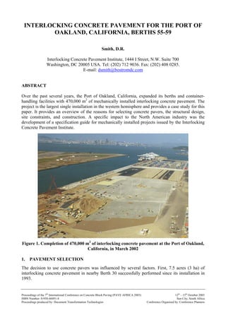
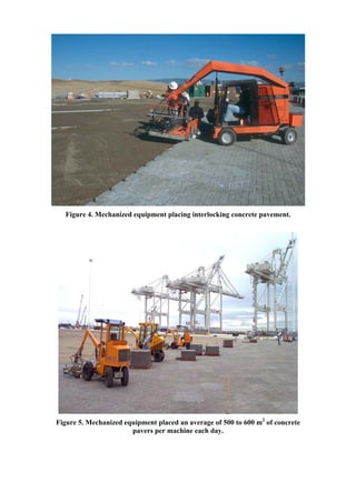
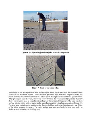

This document summarizes a large interlocking concrete pavement project at the Port of Oakland in California. The project covered 470,000 square meters and was the largest single installation of mechanically placed concrete pavers in the western hemisphere. Concrete pavers were selected for their flexibility to accommodate various container storage and handling equipment configurations. The pavers were placed over dredged soils, geotextiles, aggregate bases, and asphalt layers to provide structural support and containment of potential leachates from the soils. Layers of pavers up to 1,300 square meters in size were mechanically installed at a rate of 500-600 square meters per machine per day.


