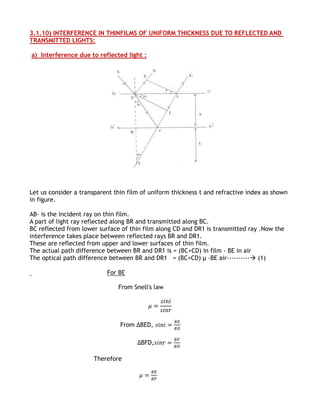
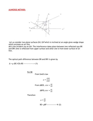
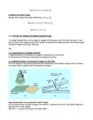
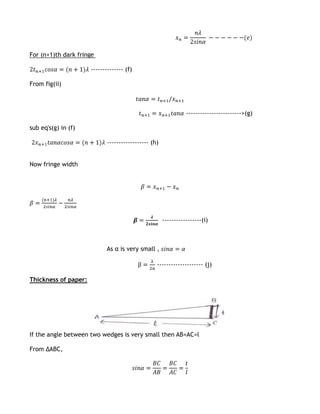
The document discusses interference of light waves. It defines key terms like phase difference, path difference, coherence and describes the principles of constructive and destructive interference. Interference in thin films of uniform and non-uniform thickness is explained. Specific applications of the wedge method are described, including determining the thickness of a paper or other thin film by measuring the fringe width in a wedge-shaped air film.
Interference of light refers to the redistribution of light energy due to superposition of two light waves. This superposition leads to a pattern of alternate dark and bright fringes. These dark and bright fringes are called as minima and maxima respectively.
Light waves superimpose each other and the redistribution of energy due to this can be observed in terms of well defined patterns of maxima and minima. Wherein, maxima refers to more energy and minima refers to less energy. Diffraction can also be called as interference in secondary wavelets.
Polarization of light, Types of Polarization, Plane polarized light and its production, Circular Polarization, Elliptical Polarization, E -ray , O-ray, Positive and negative crystals, Quarter wave plate and half wave plate.
The slide is about single slit diffraction. this slide gives a complete presentataion on the same. it also contains interesting pictures to get a better idea of the topic.
FellowBuddy.com is a platform which has been setup with a simple vision, keeping in mind the dynamic requirements of students.
Our Vision & Mission - Simplifying Students Life
Our Belief - “The great breakthrough in your life comes when you realize it, that you can learn anything you need to learn; to accomplish any goal that you have set for yourself. This means there are no limits on what you can be, have or do.”
Like Us - https://www.facebook.com/FellowBuddycom-446240585585480
This LO presents conditions for constructive and destructive thin film interference. An example of thin film interference in butter fly wings with a worked solution is provided to assist in application of the concepts and demonstrate the real life applications of this topic.
Physics Investigated Project for CBSE Class 12
To get the whole "WORD" file DM me at
wadhawan.maanit@yahoo.com
Or Watsapp- 6389004709
( INCLUDING COVER PAGE, CERTIFICATE, AKNOWLEDGEMENT,INDEX, THEORY AND BIBLIOGRAPHY)
State of ICS and IoT Cyber Threat Landscape Report 2024 previewPrayukth K V
The IoT and OT threat landscape report has been prepared by the Threat Research Team at Sectrio using data from Sectrio, cyber threat intelligence farming facilities spread across over 85 cities around the world. In addition, Sectrio also runs AI-based advanced threat and payload engagement facilities that serve as sinks to attract and engage sophisticated threat actors, and newer malware including new variants and latent threats that are at an earlier stage of development.
The latest edition of the OT/ICS and IoT security Threat Landscape Report 2024 also covers:
State of global ICS asset and network exposure
Sectoral targets and attacks as well as the cost of ransom
Global APT activity, AI usage, actor and tactic profiles, and implications
Rise in volumes of AI-powered cyberattacks
Major cyber events in 2024
Malware and malicious payload trends
Cyberattack types and targets
Vulnerability exploit attempts on CVEs
Attacks on counties – USA
Expansion of bot farms – how, where, and why
In-depth analysis of the cyber threat landscape across North America, South America, Europe, APAC, and the Middle East
Why are attacks on smart factories rising?
Cyber risk predictions
Axis of attacks – Europe
Systemic attacks in the Middle East
Download the full report from here:
https://sectrio.com/resources/ot-threat-landscape-reports/sectrio-releases-ot-ics-and-iot-security-threat-landscape-report-2024/
Elevating Tactical DDD Patterns Through Object CalisthenicsDorra BARTAGUIZ
After immersing yourself in the blue book and its red counterpart, attending DDD-focused conferences, and applying tactical patterns, you're left with a crucial question: How do I ensure my design is effective? Tactical patterns within Domain-Driven Design (DDD) serve as guiding principles for creating clear and manageable domain models. However, achieving success with these patterns requires additional guidance. Interestingly, we've observed that a set of constraints initially designed for training purposes remarkably aligns with effective pattern implementation, offering a more ‘mechanical’ approach. Let's explore together how Object Calisthenics can elevate the design of your tactical DDD patterns, offering concrete help for those venturing into DDD for the first time!
Epistemic Interaction - tuning interfaces to provide information for AI supportAlan Dix
Paper presented at SYNERGY workshop at AVI 2024, Genoa, Italy. 3rd June 2024
https://alandix.com/academic/papers/synergy2024-epistemic/
As machine learning integrates deeper into human-computer interactions, the concept of epistemic interaction emerges, aiming to refine these interactions to enhance system adaptability. This approach encourages minor, intentional adjustments in user behaviour to enrich the data available for system learning. This paper introduces epistemic interaction within the context of human-system communication, illustrating how deliberate interaction design can improve system understanding and adaptation. Through concrete examples, we demonstrate the potential of epistemic interaction to significantly advance human-computer interaction by leveraging intuitive human communication strategies to inform system design and functionality, offering a novel pathway for enriching user-system engagements.
Transcript: Selling digital books in 2024: Insights from industry leaders - T...BookNet Canada
The publishing industry has been selling digital audiobooks and ebooks for over a decade and has found its groove. What’s changed? What has stayed the same? Where do we go from here? Join a group of leading sales peers from across the industry for a conversation about the lessons learned since the popularization of digital books, best practices, digital book supply chain management, and more.
Link to video recording: https://bnctechforum.ca/sessions/selling-digital-books-in-2024-insights-from-industry-leaders/
Presented by BookNet Canada on May 28, 2024, with support from the Department of Canadian Heritage.
Key Trends Shaping the Future of Infrastructure.pdfCheryl Hung
Keynote at DIGIT West Expo, Glasgow on 29 May 2024.
Cheryl Hung, ochery.com
Sr Director, Infrastructure Ecosystem, Arm.
The key trends across hardware, cloud and open-source; exploring how these areas are likely to mature and develop over the short and long-term, and then considering how organisations can position themselves to adapt and thrive.
Software Delivery At the Speed of AI: Inflectra Invests In AI-Powered QualityInflectra
In this insightful webinar, Inflectra explores how artificial intelligence (AI) is transforming software development and testing. Discover how AI-powered tools are revolutionizing every stage of the software development lifecycle (SDLC), from design and prototyping to testing, deployment, and monitoring.
Learn about:
• The Future of Testing: How AI is shifting testing towards verification, analysis, and higher-level skills, while reducing repetitive tasks.
• Test Automation: How AI-powered test case generation, optimization, and self-healing tests are making testing more efficient and effective.
• Visual Testing: Explore the emerging capabilities of AI in visual testing and how it's set to revolutionize UI verification.
• Inflectra's AI Solutions: See demonstrations of Inflectra's cutting-edge AI tools like the ChatGPT plugin and Azure Open AI platform, designed to streamline your testing process.
Whether you're a developer, tester, or QA professional, this webinar will give you valuable insights into how AI is shaping the future of software delivery.
Accelerate your Kubernetes clusters with Varnish CachingThijs Feryn
A presentation about the usage and availability of Varnish on Kubernetes. This talk explores the capabilities of Varnish caching and shows how to use the Varnish Helm chart to deploy it to Kubernetes.
This presentation was delivered at K8SUG Singapore. See https://feryn.eu/presentations/accelerate-your-kubernetes-clusters-with-varnish-caching-k8sug-singapore-28-2024 for more details.
Dev Dives: Train smarter, not harder – active learning and UiPath LLMs for do...UiPathCommunity
💥 Speed, accuracy, and scaling – discover the superpowers of GenAI in action with UiPath Document Understanding and Communications Mining™:
See how to accelerate model training and optimize model performance with active learning
Learn about the latest enhancements to out-of-the-box document processing – with little to no training required
Get an exclusive demo of the new family of UiPath LLMs – GenAI models specialized for processing different types of documents and messages
This is a hands-on session specifically designed for automation developers and AI enthusiasts seeking to enhance their knowledge in leveraging the latest intelligent document processing capabilities offered by UiPath.
Speakers:
👨🏫 Andras Palfi, Senior Product Manager, UiPath
👩🏫 Lenka Dulovicova, Product Program Manager, UiPath
Encryption in Microsoft 365 - ExpertsLive Netherlands 2024Albert Hoitingh
In this session I delve into the encryption technology used in Microsoft 365 and Microsoft Purview. Including the concepts of Customer Key and Double Key Encryption.
GraphRAG is All You need? LLM & Knowledge GraphGuy Korland
Guy Korland, CEO and Co-founder of FalkorDB, will review two articles on the integration of language models with knowledge graphs.
1. Unifying Large Language Models and Knowledge Graphs: A Roadmap.
https://arxiv.org/abs/2306.08302
2. Microsoft Research's GraphRAG paper and a review paper on various uses of knowledge graphs:
https://www.microsoft.com/en-us/research/blog/graphrag-unlocking-llm-discovery-on-narrative-private-data/
Kubernetes & AI - Beauty and the Beast !?! @KCD Istanbul 2024Tobias Schneck
As AI technology is pushing into IT I was wondering myself, as an “infrastructure container kubernetes guy”, how get this fancy AI technology get managed from an infrastructure operational view? Is it possible to apply our lovely cloud native principals as well? What benefit’s both technologies could bring to each other?
Let me take this questions and provide you a short journey through existing deployment models and use cases for AI software. On practical examples, we discuss what cloud/on-premise strategy we may need for applying it to our own infrastructure to get it to work from an enterprise perspective. I want to give an overview about infrastructure requirements and technologies, what could be beneficial or limiting your AI use cases in an enterprise environment. An interactive Demo will give you some insides, what approaches I got already working for real.
Neuro-symbolic is not enough, we need neuro-*semantic*Frank van Harmelen
Neuro-symbolic (NeSy) AI is on the rise. However, simply machine learning on just any symbolic structure is not sufficient to really harvest the gains of NeSy. These will only be gained when the symbolic structures have an actual semantics. I give an operational definition of semantics as “predictable inference”.
All of this illustrated with link prediction over knowledge graphs, but the argument is general.
GDG Cloud Southlake #33: Boule & Rebala: Effective AppSec in SDLC using Deplo...James Anderson
Effective Application Security in Software Delivery lifecycle using Deployment Firewall and DBOM
The modern software delivery process (or the CI/CD process) includes many tools, distributed teams, open-source code, and cloud platforms. Constant focus on speed to release software to market, along with the traditional slow and manual security checks has caused gaps in continuous security as an important piece in the software supply chain. Today organizations feel more susceptible to external and internal cyber threats due to the vast attack surface in their applications supply chain and the lack of end-to-end governance and risk management.
The software team must secure its software delivery process to avoid vulnerability and security breaches. This needs to be achieved with existing tool chains and without extensive rework of the delivery processes. This talk will present strategies and techniques for providing visibility into the true risk of the existing vulnerabilities, preventing the introduction of security issues in the software, resolving vulnerabilities in production environments quickly, and capturing the deployment bill of materials (DBOM).
Speakers:
Bob Boule
Robert Boule is a technology enthusiast with PASSION for technology and making things work along with a knack for helping others understand how things work. He comes with around 20 years of solution engineering experience in application security, software continuous delivery, and SaaS platforms. He is known for his dynamic presentations in CI/CD and application security integrated in software delivery lifecycle.
Gopinath Rebala
Gopinath Rebala is the CTO of OpsMx, where he has overall responsibility for the machine learning and data processing architectures for Secure Software Delivery. Gopi also has a strong connection with our customers, leading design and architecture for strategic implementations. Gopi is a frequent speaker and well-known leader in continuous delivery and integrating security into software delivery.
2. STRUCTURE:
3.1.1. INTRODUCTION
OBJECTIVES
3.1.2. LIGHT AS A WAVE
3.1.3. PHASE DIFFERENCE
3.1.4. PATH DIFFERENCE
3.1.5. RELATION BETWEEN PHASE DIFFERENCE AND PATH DIFFERENCE
3.1.6. COHERENCE
3.1.7. INTERFERENCE (DEFINITION)
1. PRINCIPLE OF SUPERPOSITION
2. TYPES OF INTERFERENCE(CONSTRUCTIVE & DESTRUCTIVE)
3. WHEN THE LIGHT WAVES HAVING DIFFERENT FREQUENCIES AND VARYING
PHASE DIFFERENCE.
4. WHEN THE LIGHT WAVES HAVING EQUAL FREQUENCIES AND CONSTANT PHASE
DIFFEENCE
5.CONDITIONS FOR SUSTAINED INTERFERENCE
3.1.8. INTERFERENCE IN THINFILMS
1. STOKE’SPRINCIPLE
2. OPTICAL PATH OF LIGHT
3.1.9. INTERFERENCE IN THINFILMS OF UNIFORM THICKNESS DUE TO REFLECTED
AND TRANSMITTED LIGHTS
3.1.10. INTERFERENCE IN THINFILMS OF NON UNIFORM THICKNESS
1. WEDGE METHOD
(i) DETERMINATION OF THICKNESS OF PAPER
(ii) DETERMINATIO OF FLATNESS OF GIVEN GLASS PLATES
2. NEWTON’S RINGS
(i) DETERMINATION OF WAVELENGTH OF MONOCHROMATIC LIGHT
(ii) DETERMINATION OF REFRACTIVE INDEX OF A GIVEN LIQUID
3.1.11. MICHELSON INTERFERROMETER
3.1.12. QUIZ
3.1.13. SOLVED EXAMPLES
3.1.14. PROBLEMS FOR PRACTICE
3.1.15. SUMMARY
3. 3.1.1. INTRODUCTION
Sunlight, as the rainbow shows us, is a composite of all colors of visible
spectrum. The colors reveal themselves in the rainbow because the incident wave lengths
are bent through different angles as they pass through raindrops that produce a bow.
However, soap bubbles and oil slicks can also show striking colors produced not by
refraction but by constructive and destructive interference of light. The interfering waves
combine either to enhance or to suppress certain colors in the spectrum of sun light.
Interference of light waves is thus a superposition phenomenon.
This selective superposition of wavelengths has many applications. When light
encounters an ordinary glass surface, for example about 4% of incident light energy is
reflected, thus weakening the transmitted beam by the amount. This unwanted loss of light
can be a real problem in optical systems with many components. A thin transparent
“interference film” deposited on glass surface, Can reduce the amount of reflected light by
destructive interference. The bluish cast of camera lens reveals the presence of such a
coating. Interference coatings can also be used to enhance –rather than reduce- the ability
of a surface to reflect light.
To understand interference, we must go beyond the restrictions of geometrical
optics and employ the full power of wave optics. In fact, as you will see, the existence of
interference phenomena is perhaps our most convincing evidence that light is a wave-
because interference cannot be explained other than with waves.
OBJECTIVES:
After going through this chapter we should able to: know
1) About light wave.
2) The relation between path difference and phase difference.
3) About interference.
4) About the interference phenomenon takes place in thin films.
5) Determination of thickness of a paper using wedge method.
6) Determination of wavelength of monochromatic light using Newton’s rings.
3.1.2) LIGHT AS A WAVE:
Light has dual nature. It has both particle nature and wave nature but it cannot act as a
wave and particle simultaneously. Light is also having the properties such as reflection,
refraction, interference, diffraction, polarization. Light is also having two most famous
effects like photoelectric effect and Compton Effect. To explain the properties like
interference diffraction and polarization we need to adopt wave nature for light.
Light is a transverse wave.
The first person to advance a convincing wave theory for light was DUTCH PHYSICIST
CHRISTIAN HUYGENS, in 1678.
Light wave should be represented as follows.
Figure1
4. Whose displacement is given b
Where ' a' is amplitude of wave.
'ωt' is Phase, Which gives the position and direction of wave at a time 't'
3.1.3) PHASE DIFFERENCES:
The angular separation between two points of wave is called Phase difference.
It is measured in radians or degrees.
3.1.4) PATH DIFFERENCE:
The linear separation between two points of wave is called Path Difference
It is measured in mm or cm.
Fig.
3.1.5) RELATION BETWEEN PHASE DIFFERENCE AND PATH DIFFERENCE:
Figure
2 Phase Difference = λ Path Difference
Phase Difference = Path Difference
5. Therefore for
2 Phase Difference = λ (Path Difference)
Phase Difference (δ)= What is the Path Difference(X)
=
δ = ( ) x path difference
Phase Difference= ( ) x Path Difference
Path Difference = ( ) x Phase Difference
3.1.6) COHERENCE:
Two light waves are said to be coherent if they are having
1) Same Frequency
2) Almost Same Amplitude
3) Moving in a medium with either zero or constant Phase Difference
4) S
3.1.7) INTERFERENCE:
Interference is the optical phenomenon in which brightness and darkness are
produced by the combination of two similar light waves.
DEFINITION:
When two light waves of same frequency having constant phase difference coincide in
space and time. There is modification in the intensity of light.
The resultant intensity at any point depends upon amplitudes and phase relationships
between two waves.
This modification in the intensity is due to superposition of two light waves are called
Interference.
And the pattern dark and bright fringes produced are called Interference pattern.
6. (i)PRINCIPLES OF SUPERPOSITION:
When two or more waves reach a point simultaneously, the resultant displacement
at that point is the algebraic sum of the displacements produced by the individual waves in
absence of others.
Explanation: Let us consider the two waves of same frequency “ ” is
If y1 is the displacement produced by one wave and
y2 is the displacement produced by second wave
δ is the phase difference between these two waves
The resultant displacement produced by the superposition of these waves is
(1)
Let (2)
(3)
Where a1 and a2 are the amplitudes of these two waves
Substitute equation (2) and (3) in (1), we get
7. (4)
Let (5)
(6)
Sub eq(5) and eq(6) in (4) then
(7)
This is an equation for resultant displacement.
Where A is resultant amplitude which can be calculated as follows.
By squaring and Adding equation (5) and equation (6)
=
Square of the amplitude (A²) = Intensity of light (I)
(2)TYPES OF INTERFERENCE:
Interference is of two types.
1. Constructive interference / constructive superposition
2. Destructive interference / destructive superposition
8. Figure: Constructive and Destructive Interference
(A)CONSTRUCTIVE INTERFERENCE:
When crust of one light wave falls on the crust of another wave then the
resultant intensity increases and this type of interference is called constructive
interference.
Here we get maximum intensity.
The intensity becomes maximum ) when
9. , n=0, 1, 2, 3...............
For δ=0, 2π, 4π.............we get bright band
Path Difference = ) X Phase Difference
Path Difference= ) x2nπ
Path Difference=
This is the condition for constructive interference.
`
For δ=0, 2π, 4 ………
s
(B)DESTRUCTIVE INTERFERENCE:
When crust of one light wave falls on the trough of another wave then the
resultant intensity decreases. This type of interference is called destructive interference.
Here we get minimum intensity.
The intensity becomes minimum ) when
, n=0, 1, 2, 3...............
For .............we get dark band.
Path Difference = )X Phase Difference
Path Difference=
Path Difference=
10. This is the condition for constructive interference.
`
For δ= , 3π, 5 ………
Variation of Intensity with phase:-
3) When two light waves having different frequencies and varying phase difference:
If two light waves have different frequencies and the phase difference between
light waves is not constant then we get unsustained interference pattern i.e., Uniform
illumination is observed i.e., bright and dark bands cannot be seen.
11. 4)When two light waves having equal frequencies and constant phase difference:
If two light waves having equal frequencies and constant phase difference then we
get sustained interference pattern. i.e we get alternative bright and dark fringes. Here the
bright fringe becomes very bright and dark fringe becomes very dark.
To get sustained interference light waves has to be satisfying the following conditions.
5)Conditions for sustained or Good interference pattern :
1) We require two monochromatic light sources.
2) These two sources must be coherent i.e., they constant phase difference.
3) The frequency must be the same.
4) The amplitude must be the same.
5) They must travel in the same directions.
6) The two sources must be the same
7) These two sources must be as near as possible and the screen must be as far from
them as possible.
3.1.9) INTERFERENCE IN THIN FILMS:
To understand interference in thin films first of all we have to understand some basic
concepts like stokes principle and optical path.
1) STOKE'S PRINCIPLE:
STATEMENT:-
According to stoke principle, a light beam which is initially passing through a rarer
medium reflects back into the same rare medium from denser medium suffering sudden
phase change of ∏ or path change of λ/2.Such a phase change cannot be observed for a
light beam light beam which is initially passing through denser medium and reflects back
into the same medium.
12. 2) The second basic point is Optical Path:
The optical path travel led by a light beam in a medium of refractive index 'μ' is not equal
to actual path travel led by the light beam.
Optical path travelled by light beam =µ X Actual path travelled by light
Thin films are of two types
1) Thin films which have uniform thickness
2) Thin films which have non uniform thickness
Striking colors observed on thin films due to interference
13. 3.1.10) INTERFERENCE IN THINFILMS OF UNIFORM THICKNESS DUE TO REFLECTED AND
TRANSMITTED LIGHTS:
a) Interference due to reflected light :
Let us consider a transparent thin film of uniform thickness t and refractive index as shown
in figure.
AB- is the incident ray on thin film.
A part of light ray reflected along BR and transmitted along BC.
BC reflected from lower surface of thin film along CD and DR1 is transmitted ray .Now the
interference takes place between reflected rays BR and DR1.
These are reflected from upper and lower surfaces of thin film.
The actual path difference between BR and DR1 is = (BC+CD) in film - BE in air
The optical path difference between BR and DR1 = (BC+CD) µ -BE air---------- (1)
For BE
From Snell's law
From ∆BED,
∆BFD,
Therefore
14. BE= µBF--------------- (2)
Sub eq’n (2) in eq’n (1)
Path difference ∆= (BC+CD) µ - µBF
= (BC+CD-BF) µ
= (BC+CF) µ ------------ (3)
∆le BCQ, ∆le PCQ are congruent triangles.
Therefore
BC=PC
BQ=PQ=t
QC is common side and all angles are equal.
Therefore ∆= (PC+CF) µ
∆=µ (PF) ------------- (4)
From ∆le PBF
PF= (PB)
= (BQ+QP)
=
= 2t ---------- (5)
Therefore eq’n (4) becomes
∆= µ (2t)
∆=2µt --------- (6)
But according to stokes principles the light ray BR is undergoing additional path change of
λ /2.
Therefore the total path difference between BR and DR is equal to 2μtcosr± λ /2
15. Condition for bright band/bright fringes
We get bright fringes when path difference =n λ
Condition for dark band/dark fringes
we get dark fringes when the path difference
3.4) NOTE:
In thin film, due to transmitted light
The conditions for bright is
The conditions for dark is
We can say the interference pattern due to reflected and transmitted rays are
complementary each other.
3.1.11) INTERFERENCE IN THIN FILMS OF NON UNIFORM THICKNESS:
1) Wedge method
2) Newton’s Rings
16. (A)WEDGE METHOD:
Let us consider two plane surfaces GH; GH1which is inclined at an angle gives wedge shape
which encloses an air film
AB is the incident ray on GH. The interference takes place between two reflected rays BR
and DR1.One is reflected from upper surface and other one is from lower surface of air
film.
The optical path difference between BR and DR1 is given by
Δ = µ (BC+CD)-BE----------------> (1)
For BE
From Snell's law
From ∆BED,
∆BFD,
Therefore
BE= µBF--------------- (2)
17. Substitute equation (2) in equation (1)
Δ =µ (BC+CD)-µBF
Δ =µ (BC+CD-BF)
Δ =µ (BC- BF+CD)
Δ =µ (FC+CD) -----------------------------> (3)
ΔCDQ, ΔCPQ are congruent triangles
CD=CP
Therefore Eq’n (3) becomes
Δ =µ (FC+CP)
Δ =µ (FP) -----------------------> (4)
From ΔFPD
FP=2t ------------------>(5) (from figure DP=2t)
Sub (5) in (4)
Δ=2µt --------------------------------- (6)
From stoke principle
The ray BR undergoes reflection from denser medium; it suffers on additional path change
λ/2.
Therefore the total path difference=
Condition for bright fringe:
We get bright fringes when path difference =nλ
18. Condition for dark fringe:
We get dark fringe when path difference=
3.4.2)TYPES OF FRINGES IN WEDGE SHAPED FILMS:
In wedge shaped films ,at the edge of wedge the thickness of air film will be same .If we
draw a line at this edge all along this length we observed straight parallel alternative bright
and dark fringes with equal Spacing.
Fig
3.4.3)Applications of Wedge method:
1) Determination of thickness of a paper or diameter of a wire/hair.
2) Verification of flatness of the given transparent surface.
3.4.4)Determination of thickness of paper or thin film
First we measure the spacing between two consecutive dark/bright fringes which is known
as fringe width to determine the thickness of paper.
Spacing between two consecutive dark fringes
Let us assume that nth dark fringes is formed at a distance Xn and (n+1)th dark fringe at a
distance Xn+1 from wedge.
Now Xn+1 – Xn gives the values of fringe width ''.
19. Condition for dark fringe is -------------- (a)
For normal incidence i=0
r=0
For air µ =1
Eq--(a) becomes
------------------------->(b)
For nth dark fringe
--------------------------(c)
From figure (ii)
---------------- (d)
Sub eq (d) in eq(c)
20. For (n+1)th dark fringe
-------------- (f)
From fig(ii)
------------------------>(g)
sub eq's(g) in (f)
------------------ (h)
Now fringe width
-----------------(i)
As α is very small ,
-------------------- (j)
Thickness of paper:
If the angle between two wedges is very small then AB=AC=l
From ΔABC,
21. This is equation (k)
Sub eq’n (k) in eq’n(i), fringe width becomes
This is an expression for thickness of paper.
Where
λ = wavelength incident light
l = length of air film
β = Fringe width
(B)NEWTON'S RINGS:
Plano-convex lens on flat black surface
When a Plano convex lens with its convex surfaces is placed on glass plate air film is
formed between two whose thickness increases gradually. The thickness of air film at the
point of contact is zero. When monochromatic light is allowed to fall normally then we get
fringes which are circular. These fringes are concentric circle, uniform in thickness and with
the point of contact as the center. This phenomenon was first described by Newton that
why they are known as Newton’s rings.
22. Experimental arrangement
L is a planoconvex lens with large radius of curvature .
G is a plane glass plate
L is placed with its convex surface on G.
monochromatic light is incident on L normally by using 45° arrangement of glass
plate.
A part of light is reflected from curved surface of lens and another one is reflected
from plane surface of glass plate.
Now interference take place between these two rays
i.e one is reflected from upper surface of air film and another one reflected from
lower surface of air film.
Thus we get alternative bright and dark fringes .
Here we get central ring as dark ring , the reason is as follows :
The path difference between two light rays due to reflected light equal to
Due to large radius of curvature of lens, α is so small and it is neglected.
For normal incidence i=0, r=0.
For air film μ=1
Path difference from equation 1 becomes
Path difference =2t+λ/2------------ (2)
At point of contact of lens and glass plate, t=0 then eq--( 2) becomes
23. The path difference = λ/2---------- (3)
This is a condition for minimum intensity.
So central ring is dark due to reflected light.
Conditions for bright and dark rings:
Conditions for bright rings:
We observe maximum intensity/ bright ring when path difference=n λ
2t+λ/2=n λ (from eq---2)
2t= (2n-1) λ/2----------- (4)
Conditions for dark rings:
We observe minimum intensity/ dark ring
When Path difference = (2n+1) λ/2
(from 2)
2t=n λ------------------ (5)
Calculation of Diameter of bright and Dark rings formed due to reflection of light :
fig
24. (Here d=t)
From Figure
t = thickness of air film
D=Diameter of Newton's rings
r=Radius of Newton’s ring =D/2
R = Radius of curvature of convex lens
25. From properties of chords in circle
ON * OD = OP *OQ
t(2R - t) = r * r
2Rt-t ² = r ²
2Rt-t ²= (D/2)² =D²/4
D²= 8Rt-4t²
As the thickness of air film is very small,t² is neglected.
D²= 8Rt
D²= 4R(2t)
Condition for Diameter of bright ring
From (4)
Diameter of bright rings is proportional to square root of odd natural numbers.
Diameter of Dark Ring:
From eq-5
The diameter of the dark ring is proportional to square root of natural numbers.
26. Note:
The distance between rings decreases when the order of rings increases.
Reason:
Condition for dark ring is
D16= 8√Rλ
D9= 6√Rλ
D4= 4√Rλ
D1= 2√Rλ
D16 -D9=2√Rλ ------------->7 Fringes
D9-D4 = 2√Rλ -------------->5 fringes
D4-D1= 2√Rλ ---------------->3 Fringes
Here the distance( 2√Rλ) remains constant but number of rings increases .
From this we can say that width decreases as order increases.
APPLICATIONS:
1) Determination of wavelength of monochromatic source
2) Determination of refractive index of liquid
1) Determination of wavelength of monochromatic source
First Newton's Rings are formed by respective experimental arrangement.
The condition for diameter of dark ring is given by
If we consider mth dark ring
27. The diameter for mth dark ring is given by
------------------ (a)
If we consider nth dark ring
The diameter for nth dark ring is given by
---------------------- (b)
Equation (a) - equation(b)
This is equation(c)
R is radius of curvature of lens is measured by spherometer.
R=l²/6h+h/2
Where
l is the distance between two legs of spherometer.
h is height of convex lens.
(ii) DETERMINATION OF REFRACTIVE INDEX OF A LIQUID
First the experiment is performed when there is an air film is formed between glass plate
and Plano convex lens.
The diameter of nth and mth rings are measured.
For air film,
This is equation (d)
Now the liquid whose refractive index is to be measured is powered in the container
without disturbing the whole arrangement.
Again we measured the diameter of mth and nth rings whose diameters are D'²m and D'²n
For liquid medium
28. This is equation (e)
From eq (d) /eq (e) then we get
APPLICATIONS
1) Determination of wavelength of monochromatic light.
2) Determination of difference of nearly equal wavelengths
1)DETERMINATION OF WAVELENGTH OF MONOCHROMATIC LIGHT:
Michelson interferometer is set for circular fringes set bright at center.
Condition for bright spot
The mirror M1 is set at a distance x1 for one fringe.
Let it be zeroth fringe.
The mirror M1 is moved from x1 to x2 N fringes are crossed
2(X2~X1) =Nλ
λ=2/N(X2~X1)
2)DETERMINATION OF DIFFERENCE IN WAVELENGTH:
There are two spectral lines D1 and D2 of sodium light.
Their wavelengths are nearly equal.
The difference in their wavelengths of D1 and D2 lines.
So they form two separate fringe n .
As thickness between M2 and M2¹ is very small, two fringe patterns coincide practically.
By moving M1 we separate these two fringe pattern s.
We move M 1 so that nth bright fringe of λ1 coincides with (n+1)th dark fringes of λ2.
Note Down this distance , At this position we observe indistinctness.
We move M2 again another indistinctness is observed .Let the fringe distance be x.
For nth fringe
29. 2x=nλ1
This is equation (1)
For (n+1)th fringe
2x= (n+1)λ2
This is equation (2)
Equation (2) – equation (1)
This is difference between wavelengths.
3.1.13)QUIZ
WHY RAINBOW FORMS:
30. WHY MORPHO’S BUTTERFLY CHANGES IT’S COLOR FROM BLUE TO BROWN
.
.
3.1.14) SOLVED EXAMPLES:
(1)Two coherent sources of intensity 10 w and 25 w interfere to from fringes. Find
the ratio of maximum intensity to minimum intensity.
Solution:
Given that =
Hence =
Now =
=
=19.724
(2)Two sinusoidal waves of equal amplitudes are wavelength out of phase. What is the
amplitude of the resultant?
Solution:
When two waves of equal amplitude but different phase superpose, the resultant intensity
is
I=4
Or resultant amplitude is
A=2acos
31. Where Ø is the phase difference.
Given path difference =
Hence phase difference Ø= Χ =
Hence A=2a cos
=2a =
(3) A soap film of refractive index 4/3 and of thickness 1.5Χ cm is illuminated by white
light incident at an angle of 60º. The light reflected by it is examined by a spectrometer in
which is found a dark band corresponding to a wavelength of 5Χ Calculate the order
of interference of the dark band.
Solution:
For dark band 2µtcosr= λ
Given =60º
Hence µ=
Or sin = =
=0.6511
i.e.,
3.1.15) PROBLEMS FOR PRACTICE
1) Two coherent source of intensity ratio interfere. Prove that in the interference
pattern
2) Two coherent sources whose intensity ratio is 81:1 produce interference fringes
.Deduce the ratio of maximum intensity to minimum Intensity.
3) A parallel beam of light is incident on a thin glass plate such that the angle of
refraction into the plate is 60°. Calculate the smallest thickness of the glass plate
which will appear dark by reflection.
4) Fringes of equal thickness are observed in a thin glass wedge of refractive index, the
fringe spacing is 1mm and wavelength of light is 5893 A°. Calculate the angle of
wedge.
5) In Newton's Rings experiment, the diameter of the 4th and 12th dark rings is 0.400 cm
and 0.700cm respectively. Find the diameter of 20th dark ring.
6) In Newton's Rings experiment, the diameter of the 10th rings from 1.40 cm to
1.27cm when a liquid is introduced between the lens and the plate. Calculate the
32. refractive index of the liquid.
7) Light containing two wavelengths λ1 and λ2 falls normally on a Plano convex lens
of radius of curvature R resting on a glass plate .If nth dark ring due to λ1 coincides
with (n+1)th dark ring due to λ2 prove that radius of nth dark ring of λ1 is
8) In a Michelson interferometer 200 fringes cross the field of view when the movable
mirror is displaced through 0.0589 mm .Calculate the monochromatic light
wavelength.
9) The movable mirror of Michelson's interferometer is moved through a distance of
0.02603 mm. find the number of fringes shifted across the cross wire of eye piece of
the telescope ,if a wavelength of 5200 A° is used.
10) In an experiment with Michelson's interferometer scale readings for a pair of
maximum indistinctness were found to be 0.6939 mm and 0.9884 mm .If the mean
wavelength of the two components of D line are 5893 A°. Deduce the difference
between wavelengths.
3.1.17) SUMMARY:
We have seen that two independent sources of light cannot acts as coherent sources. Even
two different parts of the same lamp cannot acts as coherent sources of light. Hence we
choose a ray which splits into two different parts such as reflected and transmitted to get
two coherent waves. Due to the path difference between such split rays interference
occurs. The phenomena of interference are very useful in many areas such as holography
optical switching calibration of instruments, displacements and measurements.
The displacement of wave light is
y=a sin (wt+ δ)
Relation between path difference and phase difference
Path Difference= λ /2∏ * Phase Difference
From principle of superposition
The intensity of resultant wave is given by
I=a1²+a2²+2a1a2cosδ
Intensity I= A²
When a1 =a2 =a
I=4a²cos²δ/2
A²=4a²cos²δ/2
A=2acosδ/2
Condition for maximum intensity /Bright fringe
Path difference=nλ
Phase difference =2nπ for n=0, 1,2.......
I max= (a1+a2)²
Condition for minimum Intensity/dark fringe
Path difference= (2n±1) λ / 2
Phase difference= (2n±1) π for n=0, 1, 2.....
I min= (a1-a2)²
33. Interference in thin film for uniform thickness thin films:
Condition for bright and dark fringes due to reflected light
For Bright 2μtcosr= (2n ± 1) λ /2
For dark 2μtcosr=n λ
Conditions for bright and dark fringes due to transmitted light
For dark 2μtcosr=(2n ± 1) λ /2
For bright 2μtcosr=n λ
Interference due to reflected and transmitted lights are complimentary
to each other.
B)FOR NONUNIFORM THICKNESS THIN FILMS:
Wedge method:
Bright fringe condition 2μtcos(r+α )=(2n ± 1) λ /2
Dark fringe condition 2μtcos(r+α )=nλ
Fringe width β =λ /2sin α or λ /2α
Thickness of thin film t= λl/2β
Newton's Rings:
Condition for bright ring 2t=(2n -1) λ /2
Condition for dark ring 2t=nλ
Diameter of bright ring Db= √2R λ √ (2n-1
Diameter of dark ring Dd= √2R λ √n
Wavelength of monochromatic light λ=D²m - D²n/4R(m - n) where R=l²/6h+h/2
Refractive index of a liquid µ liquid= D²m - D²n / D'²m - D'²n