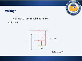
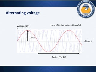
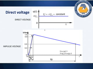
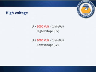
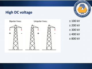
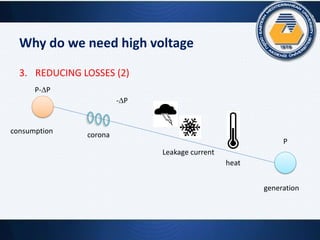
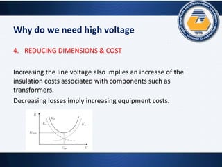
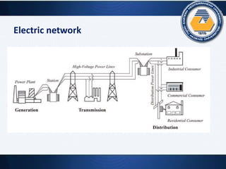
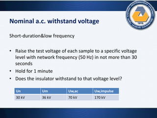
This document provides an overview of high voltage techniques. It defines key concepts like voltage, potential, alternating voltage, and direct voltage. It explains why high voltages over 1000V are needed, such as to transmit more power over long distances with lower losses. The document also discusses high voltage levels used in Turkey and Northern Cyprus. It covers insulation, withstand voltages, overvoltages, and the importance of insulation coordination in electrical networks.
![High voltage levels in Turkey
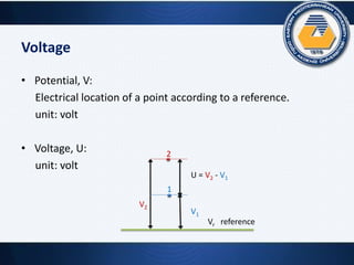
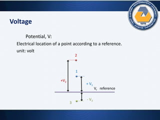
Nominal
voltage, Un
kV
Permissible
maximum
operating voltage,
Umax [kV]
Medium
voltage
3 3.6
6 7.2
10 12
15 17.5
20 24
30 (34.5) 36
High
voltage
66 72
154 170
Extra high
voltage
380 420 (400)](https://image.slidesharecdn.com/turkeyhv-160209113727/85/Turkey-hv-9-320.jpg)
![High voltage levels in TRNC
Nominal
voltage, Un
kV
Permissible
maximum
operating voltage,
Umax [kV]
Medium
voltage
11 12
22 24
High
voltage
66 72
132 145](https://image.slidesharecdn.com/turkeyhv-160209113727/85/Turkey-hv-10-320.jpg)


![1502957304lectrure_1 [Autosaved].pptx](https://cdn.slidesharecdn.com/ss_thumbnails/1502957304lectrure1autosaved-230615110736-8bee5be3-thumbnail.jpg?width=640&height=640&fit=bounds)


