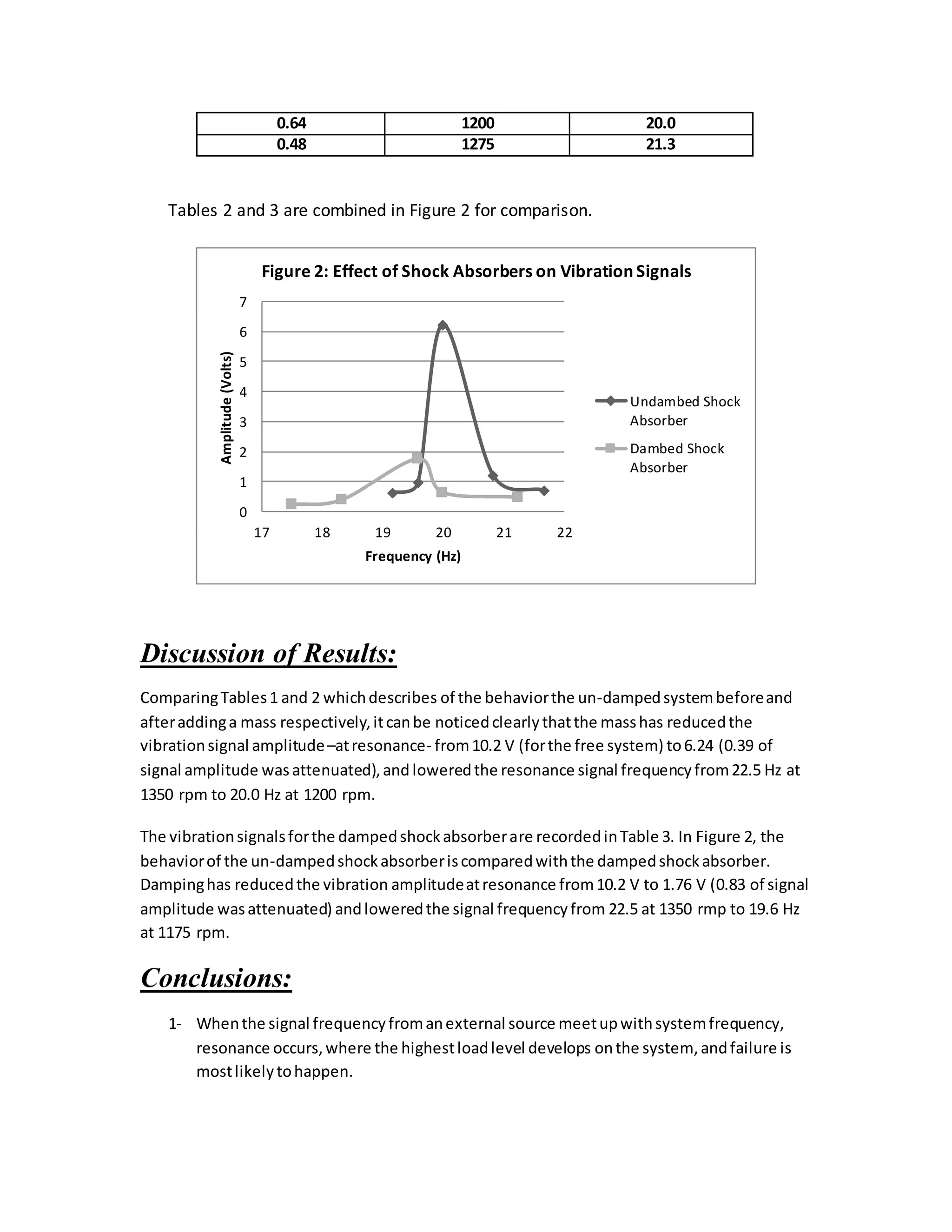
Jordan University of Science and Technology
Faculty of Engineering
Department of Mechanical Engineering
Instrumentation and Dynamic Systems Lab
Experiment #12: Lateral Beam Vibration
Abstract:
In thisexperiment,twotypesof vibrationabsorbers where discussed;the un-dampedshock
absorber,andthe dampedshockabsorber.Afteraddinga massto the un-dampedsystem 39%
of the signal wasattenuatedandthe resonance frequencywasloweredfrom22.5 Hz to 20 Hz.
Afterwardsadamperwas attachedto the systemandlargerportionof the signal wasabsorbed
by the damper.About 83% of the signal wasabsorbed,andthe frequencyisfurtherlowered
comparedto the un-dampedsystem.The resultsare discussedandconclusionsare stated.
Introduction:
The vibrationof a beamisveryimportantto be considered,becausebeamsare usedwidelyin
engineeringapplications,suchasthe structuresandframesin buildings.These beamsare
subjectedtoexternal forceswhichcause themtorespondinthe formof vibration,whichis
consideredasaninfinite frequencyvibration,i.e.the beamhasan infinite frequenciesthatis
vibratingwith,andthese frequenciesare dependentonthe suspensiontype,eitherasimply
supported,cantilever….etc.
The resonance isa definitionof the equalityof boththe frequencyof the drivingforce with
the natural frequencyof the system;the latterisa propertydependsonthe effectivemassand
stiffnessof the system.Asthesetwofrequenciesare equal,the systemresponseismagnified,
i.e.the response amplitudeisenlarged.Indesignissue,the machinesshouldbe preventedfrom
the resonance response,because whenthe responseamplitude ismagnified,the transported
force to the machine isalsomagnified,whichmaycause the systemtobe destroyed.
In some applications,the operatingfrequencyof the machine orhe systemcan't be changed
to avoidresonance andthe machine massor stiffnessshouldbe alsofixedtosatisfyanother
specifications,sothe needtocompensate thisphenomenonisstill presented.The
compensationof resonance isdone bya two systems.
 VibrationIsolator:
A systemconsistsof a mass,springanda damper,whichworksonisolatingthe forcingvibration,
whichisundesired,fromoursystemormachine,byconvertingthisvibratingenergyintoheatin
the damper.Thisapplicationiswidelyusedinthe Base ExcitationVibrationSystem,suchasthe
motionof an automobile onawavyroad, the excitationiscomingfromthe irregularitiesof the
road, andthe response of the automobile suspensionsystemwill isolate the automobile body
fromthisexcitationandtendstoreduce itas possible.
 Vibration Absorber:
This system consists of a mass-spring system, and the function of such system is to
absorb the excitation of the external forcing vibration, and transport it into another system
that is added to the original system or our considered machine, so when the driving or the
external excitation reaches the natural frequency of our system, the maximum amplitude
response, i.e. force, is released from our system to the added mass-spring system, this
system is called the absorber system.
Equipment and instrumentations :
1- Apparatus:
Simply supported beam (our considered system), with a rotor having unbalance
rotating shaft (as the external exciter).
2- Vibration absorber system:
Which is a cantilever beam suspended to our beam system.
Procedure:
Part 1: 1-Un-damped Vibration (Shock) Absorber
1- Suspend the system as shown in figure "1" without the absorber system,
and turn the motor on.
2- Change the motor frequency (exciter) until the oscilloscope reads the
maximum response amplitude, i.e. reaching the resonance, and record it.
3- Shut down the motor, and suspend the absorber system, as shown in
figure "1".
4- Turn the motor on.
5- Change the position of the absorber mass until the oscilloscope reads zero
amplitude, or the best smallest amplitude, which indicates the appropriate absorber
configuration. Record the frequency of absorption.
2-Damped & Un-damped Transverse Vibration of Beam
We will use the same System as in previous part but with the following additions:
1- Use a dashpot (D2) which is clamped to the base by the support (E2).
2- Use a contactor (E5) and micrometer that is mounted vertically beneath. Which
complete the circuit of a stroboscope to determines the amplitude of vibration
(x) and the phase angle (  ) of the beam undergoing damped vibrations at any
exciting frequency.
Results:
Part 1: 1-Un-damped Vibration (Shock) Absorber
A- WithoutMass:
Table 3: Vibration Signals, Un-damped Shock Absorber (Free System)
Signal Amplitude (Volts) Rotation Speed (rpm) Signal Frequency (Hz)
10.2 1350 22.5
B- Mass Added:
Table 2: Vibration Signals, Un-damped Shock Absorber (Mass Added)
Signal Amplitude (Volts) Rotation Speed (rpm) Signal Frequency (Hz)
0.64 1150 19.2
0.96 1175 19.6
6.24 1200 20.0
1.2 1250 20.8
0.72 1300 21.7
2-Damped & Un-damped Transverse Vibration of Beam
Table 3: Vibration signals, Damped Shock absorber
Signal Amplitude (Volts) Rotation Speed (rpm) Signal Frequency (Hz)
0.24 1050 17.5
0.40 1100 18.3
1.76 1175 19.6
0.64 1200 20.0
0.48 1275 21.3
Tables 2 and 3 are combined in Figure 2 for comparison.
Discussion of Results:
ComparingTables1 and 2 whichdescribes of the behaviorthe un-dampedsystembeforeand
afteraddinga mass respectively,itcanbe noticedclearlythatthe masshas reducedthe
vibrationsignal amplitude–atresonance- from10.2 V (forthe free system) to6.24 (0.39 of
signal amplitude wasattenuated),and loweredthe resonance signal frequencyfrom22.5 Hz at
1350 rpm to 20.0 Hz at 1200 rpm.
The vibrationsignalsforthe dampedshockabsorberare recordedinTable 3. In Figure 2, the
behaviorof the un-dampedshockabsorberiscomparedwiththe dampedshockabsorber.
Dampinghas reducedthe vibration amplitudeatresonance from10.2 V to 1.76 V (0.83 of signal
amplitude wasattenuated) andloweredthe signal frequencyfrom 22.5 at 1350 rmp to 19.6 Hz
at 1175 rpm.
Conclusions:
1- Whenthe signal frequencyfromanexternal source meetupwithsystemfrequency,
resonance occurs,where the highestloadlevel develops onthe system,andfailure is
mostlikelytohappen.
0
1
2
3
4
5
6
7
17 18 19 20 21 22
Amplitude(Volts)
Frequency (Hz)
Figure 2: Effect of Shock Absorbers on Vibration Signals
Undambed Shock
Absorber
Dambed Shock
Absorber
2- The un-dampedshockabsorberreducesthe vibrationsignal amplitudeandlowersits
frequency.
3- The dampedshockabsorberattenuatesthe resonance signal amplitude more effectively
than un-dampedshockabsorbersandfurtherlowersthe resonance frequency.

Instrumentation Lab. Experiment #12 Report: Lateral Beam Vibration

  • 1.
    Jordan University ofScience and Technology Faculty of Engineering Department of Mechanical Engineering Instrumentation and Dynamic Systems Lab Experiment #12: Lateral Beam Vibration
  • 2.
    Abstract: In thisexperiment,twotypesof vibrationabsorberswhere discussed;the un-dampedshock absorber,andthe dampedshockabsorber.Afteraddinga massto the un-dampedsystem 39% of the signal wasattenuatedandthe resonance frequencywasloweredfrom22.5 Hz to 20 Hz. Afterwardsadamperwas attachedto the systemandlargerportionof the signal wasabsorbed by the damper.About 83% of the signal wasabsorbed,andthe frequencyisfurtherlowered comparedto the un-dampedsystem.The resultsare discussedandconclusionsare stated. Introduction: The vibrationof a beamisveryimportantto be considered,becausebeamsare usedwidelyin engineeringapplications,suchasthe structuresandframesin buildings.These beamsare subjectedtoexternal forceswhichcause themtorespondinthe formof vibration,whichis consideredasaninfinite frequencyvibration,i.e.the beamhasan infinite frequenciesthatis vibratingwith,andthese frequenciesare dependentonthe suspensiontype,eitherasimply supported,cantilever….etc. The resonance isa definitionof the equalityof boththe frequencyof the drivingforce with the natural frequencyof the system;the latterisa propertydependsonthe effectivemassand stiffnessof the system.Asthesetwofrequenciesare equal,the systemresponseismagnified, i.e.the response amplitudeisenlarged.Indesignissue,the machinesshouldbe preventedfrom the resonance response,because whenthe responseamplitude ismagnified,the transported force to the machine isalsomagnified,whichmaycause the systemtobe destroyed. In some applications,the operatingfrequencyof the machine orhe systemcan't be changed to avoidresonance andthe machine massor stiffnessshouldbe alsofixedtosatisfyanother specifications,sothe needtocompensate thisphenomenonisstill presented.The compensationof resonance isdone bya two systems.  VibrationIsolator: A systemconsistsof a mass,springanda damper,whichworksonisolatingthe forcingvibration, whichisundesired,fromoursystemormachine,byconvertingthisvibratingenergyintoheatin the damper.Thisapplicationiswidelyusedinthe Base ExcitationVibrationSystem,suchasthe motionof an automobile onawavyroad, the excitationiscomingfromthe irregularitiesof the road, andthe response of the automobile suspensionsystemwill isolate the automobile body fromthisexcitationandtendstoreduce itas possible.  Vibration Absorber:
  • 3.
    This system consistsof a mass-spring system, and the function of such system is to absorb the excitation of the external forcing vibration, and transport it into another system that is added to the original system or our considered machine, so when the driving or the external excitation reaches the natural frequency of our system, the maximum amplitude response, i.e. force, is released from our system to the added mass-spring system, this system is called the absorber system. Equipment and instrumentations : 1- Apparatus: Simply supported beam (our considered system), with a rotor having unbalance rotating shaft (as the external exciter). 2- Vibration absorber system: Which is a cantilever beam suspended to our beam system. Procedure: Part 1: 1-Un-damped Vibration (Shock) Absorber 1- Suspend the system as shown in figure "1" without the absorber system, and turn the motor on. 2- Change the motor frequency (exciter) until the oscilloscope reads the maximum response amplitude, i.e. reaching the resonance, and record it.
  • 4.
    3- Shut downthe motor, and suspend the absorber system, as shown in figure "1". 4- Turn the motor on. 5- Change the position of the absorber mass until the oscilloscope reads zero amplitude, or the best smallest amplitude, which indicates the appropriate absorber configuration. Record the frequency of absorption. 2-Damped & Un-damped Transverse Vibration of Beam We will use the same System as in previous part but with the following additions: 1- Use a dashpot (D2) which is clamped to the base by the support (E2). 2- Use a contactor (E5) and micrometer that is mounted vertically beneath. Which complete the circuit of a stroboscope to determines the amplitude of vibration (x) and the phase angle (  ) of the beam undergoing damped vibrations at any exciting frequency. Results: Part 1: 1-Un-damped Vibration (Shock) Absorber A- WithoutMass: Table 3: Vibration Signals, Un-damped Shock Absorber (Free System) Signal Amplitude (Volts) Rotation Speed (rpm) Signal Frequency (Hz) 10.2 1350 22.5 B- Mass Added: Table 2: Vibration Signals, Un-damped Shock Absorber (Mass Added) Signal Amplitude (Volts) Rotation Speed (rpm) Signal Frequency (Hz) 0.64 1150 19.2 0.96 1175 19.6 6.24 1200 20.0 1.2 1250 20.8 0.72 1300 21.7 2-Damped & Un-damped Transverse Vibration of Beam Table 3: Vibration signals, Damped Shock absorber Signal Amplitude (Volts) Rotation Speed (rpm) Signal Frequency (Hz) 0.24 1050 17.5 0.40 1100 18.3 1.76 1175 19.6
  • 5.
    0.64 1200 20.0 0.481275 21.3 Tables 2 and 3 are combined in Figure 2 for comparison. Discussion of Results: ComparingTables1 and 2 whichdescribes of the behaviorthe un-dampedsystembeforeand afteraddinga mass respectively,itcanbe noticedclearlythatthe masshas reducedthe vibrationsignal amplitude–atresonance- from10.2 V (forthe free system) to6.24 (0.39 of signal amplitude wasattenuated),and loweredthe resonance signal frequencyfrom22.5 Hz at 1350 rpm to 20.0 Hz at 1200 rpm. The vibrationsignalsforthe dampedshockabsorberare recordedinTable 3. In Figure 2, the behaviorof the un-dampedshockabsorberiscomparedwiththe dampedshockabsorber. Dampinghas reducedthe vibration amplitudeatresonance from10.2 V to 1.76 V (0.83 of signal amplitude wasattenuated) andloweredthe signal frequencyfrom 22.5 at 1350 rmp to 19.6 Hz at 1175 rpm. Conclusions: 1- Whenthe signal frequencyfromanexternal source meetupwithsystemfrequency, resonance occurs,where the highestloadlevel develops onthe system,andfailure is mostlikelytohappen. 0 1 2 3 4 5 6 7 17 18 19 20 21 22 Amplitude(Volts) Frequency (Hz) Figure 2: Effect of Shock Absorbers on Vibration Signals Undambed Shock Absorber Dambed Shock Absorber
  • 6.
    2- The un-dampedshockabsorberreducesthevibrationsignal amplitudeandlowersits frequency. 3- The dampedshockabsorberattenuatesthe resonance signal amplitude more effectively than un-dampedshockabsorbersandfurtherlowersthe resonance frequency.