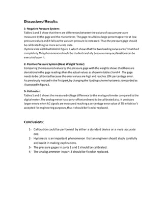
Jordan University of Science and Technology
Faculty of Engineering
Department of Mechanical Engineering
Instrumentation and Dynamic Systems Lab
Experiment #1: Calibration
Introduction:
Instrumentsystemscanbe classifiedmainlyinto Mechanical andElectrical systems.The
formerisrarelyused,simple,andlessaccurate whilethe latteriswidelyused,more
accurate and give digital outputsignals.These instrumentsare probable tohave errorsor
become lessaccurate as a resultof continuoususage whichcausesthe partsto wearor be
fatigued,thustheymustbe periodicallycheckedandfixedtokeepwithinan acceptedrange
and to inhibiterroraccumulation. Zero-offset,range errorandreadingdeviationare three
commonerrors thatoccur to instrumentdevices,calibrationisamajor processtotake care
of these typesof errors.It’sa processof comparingthe readingsof a specificinstrument
witheitherastandardor a more accurate device. Inthisexperimentthree differentsystems
are calibratednamely;negativepressure,deadweighttesterandvoltmetersystems.
Hysteresisphenomenonisthe deviationinreadingswhenmeasurementsare taken
increasinglyandthendecreasingly,itshouldbe givenagreatimportance because many
explanationscanbe executedusingthisphenomenon,suchasthe lossof energyinthe
magneticcurve.
Equipments and instruments:
1- Negative Pressure System:
A vacuumcompressorlike
the one usedina
refrigeratorisusedandis
attachedto a mercury
manometerbya valve to
control the vacuum
pressure,apressure gage
ismountedonthe valve
suctionto measure the
negative pressure value
and compare itsreadings
withthe manometersoitcan be calibrated.
2- Dead weighttester system:
In thissystemapistonisconfinedinsidea
chamberfilledof oil andconnectedtoa
pressure gage tomeasure the oil pressure
inside. Accuratelymeasuredweights are put
above the pistontoapplya pressure inside the
oil whichismeasuredbythe gage.The two
valuesare comparedandthe pressure gage is
calibrated.
3- Voltmeter:
Analogmeters(mechanical) anddigital meters
(electrical)are usedtomeasure bothDC andAC signalsbutwithlattertype being
more accurate, soa multimeterisusedtocalibrate ananalogmeter.A DC power
supplyisusedto give a DC signal while the ACsignal isgeneratedusingafunction
generator.
AC FunctionGenerator DC PowerSupply
Data Analysis:
1- Negative Pressure
Table 1: Actual and gage readings of the
mercury level in the manometer versus the
corresponding gage level increasingly.
Table 2: Actual and gage readings of the
mercury level in the manometer versus the
corresponding gage level decreasingly.
2- Dead Weight (Positive Pressure)
0
5
10
15
20
25
30
35
0 10 20 30 40
GagePressure(cm)
Manometer Pressure (cm)
Figure 1: Hysteresis in Negative Pressure System
Incrasingly Decreasingly
Actual
Manometer (cm)
Gage reading(cm)
Pressure Gage
Actual
Manometer (cm)
Gage reading
Pressure Gage (cm)
3 4 30 31
6 7 27 28
9 10 24 25
12 14 21 23
15 16 18 19
18 20 15 16
21 23 12 14
24 26 9 9
27 28 6 4
30 31 3 1
Actual Weights
(psi)
Gage Dial (psi) Actual Weights
(psi)
Gage Dial (psi)
20 22 200 181
40 37 180 172
60 55 160 155
0
20
40
60
80
100
120
140
160
180
200
0 50 100 150 200 250
GageDial(psi)
Actual Weight (psi)
Figure 2: Hysteresis in Positive Pressure System
Decreasingly Increasingly
80 73 140 132
100 90 120 112
120 112 100 95
140 131 80 72
160 150 60 58
180 172 40 40
200 181 20 22
Table 3: Actual and gage pressure
readings of the dead weight instrument
increasingly.
Table 4: Actual and gage pressure
readings of the dead weight instrument
decreasingly
3- Voltmeter
DC Scale
Actual Digital
(volt)
Gage Analog (volt)
1 0.95
2 1.93
3 2.92
4 3.90
5 4.93
6 5.96
7 6.91
8 7.91
9 8.99
10 9.94
Table 5: Actual and gage readings of
the DC analog & digital meter
increasingly.
Error = |
𝐴𝑐𝑡𝑢𝑎𝑙 −𝐴𝑝𝑝𝑟𝑜𝑥𝑖𝑚𝑎𝑡𝑒
𝐴𝑐𝑡𝑢𝑎𝑙
| ∗
100%
= |
4−3.9
4
| ∗ 100%
= 2.5%
AC Scale:
Actual Digital
(volt)
Gage Analog (volt)
1 0.89
2 1.84
3 2.79
4 3.84
5 4.83
6 5.85
7 6.87
8 7.8
9 ‫ــــــ‬
10 ‫ــــــ‬
Table 6: Actual and gage readings of
the DC analog & digital meters
decreasingly.
Error = |
𝐴𝑐𝑡𝑢𝑎𝑙 −𝐴𝑝𝑝𝑟𝑜𝑥𝑖𝑚𝑎𝑡𝑒
𝐴𝑐𝑡𝑢𝑎𝑙
| ∗ 100%
= |
3−2.79
3
| ∗ 100%
= 7%
Discussionof Results:
1- Negative Pressure System:
Tables1 and 2 showthat there are differencesbetweenthe valuesof vacuumpressure
measuredbythe gage and the manometer.The gage resultsina large percentage errorat low
pressure valuesanditfallsasthe vacuumpressure isincreased.Thusthe pressure gage should
be calibratedtogive more accurate data.
Hysteresisiswell illustratedinfigure 1,whichshowsthatthe two loadingcurvesaren’tmatched
completely.Thisphenomenonshouldbe studiedcarefullybecausemanyexplanationscanbe
executeduponit.
2- Positive Pressure System(Dead WeightTester):
Comparingthe measuredvaluesbythe pressure gage withthe weightsshowsthatthere are
deviationsinthe gage readingsthanthe actual values asshownintables3 and 4 . The gage
needstobe calibratedbecause the errorvaluesare highandreaches10% percentage error.
As previouslynoticedinthe firstpart,bychangingthe loadingscheme hysteresisisrecordedas
illustratedinfigure2.
3- Voltmeter:
Tables5 and 6 showsthe measuredvoltage difference bythe analogvoltmetercomparedtothe
digital meter.The analogmeterhasa zero-offsetandneedtobe calibratedalso.Itproduces
largererrors whenACsignals are measuredreachingapercentage errorvalue of 7% whichisn’t
acceptedforengineeringpurposes,thusitshouldbe fixedorreplaced.
Conclusions:
1- Calibration could be performed by either a standard device or a more accurate
one.
2- Hysteresis is an important phenomenon that an engineer should study carefully
and use it in making explinations.
3- The pressure gages in parts 1 and 2 should be calibrated.
4- The analog ammeter in part 3 should be fixed or replaced.

Instrumentation Lab. Experiment#1 calibration (report)

  • 1.
    Jordan University ofScience and Technology Faculty of Engineering Department of Mechanical Engineering Instrumentation and Dynamic Systems Lab Experiment #1: Calibration
  • 2.
    Introduction: Instrumentsystemscanbe classifiedmainlyinto MechanicalandElectrical systems.The formerisrarelyused,simple,andlessaccurate whilethe latteriswidelyused,more accurate and give digital outputsignals.These instrumentsare probable tohave errorsor become lessaccurate as a resultof continuoususage whichcausesthe partsto wearor be fatigued,thustheymustbe periodicallycheckedandfixedtokeepwithinan acceptedrange and to inhibiterroraccumulation. Zero-offset,range errorandreadingdeviationare three commonerrors thatoccur to instrumentdevices,calibrationisamajor processtotake care of these typesof errors.It’sa processof comparingthe readingsof a specificinstrument witheitherastandardor a more accurate device. Inthisexperimentthree differentsystems are calibratednamely;negativepressure,deadweighttesterandvoltmetersystems. Hysteresisphenomenonisthe deviationinreadingswhenmeasurementsare taken increasinglyandthendecreasingly,itshouldbe givenagreatimportance because many explanationscanbe executedusingthisphenomenon,suchasthe lossof energyinthe magneticcurve. Equipments and instruments: 1- Negative Pressure System: A vacuumcompressorlike the one usedina refrigeratorisusedandis attachedto a mercury manometerbya valve to control the vacuum pressure,apressure gage ismountedonthe valve suctionto measure the negative pressure value and compare itsreadings withthe manometersoitcan be calibrated. 2- Dead weighttester system: In thissystemapistonisconfinedinsidea chamberfilledof oil andconnectedtoa pressure gage tomeasure the oil pressure inside. Accuratelymeasuredweights are put above the pistontoapplya pressure inside the oil whichismeasuredbythe gage.The two valuesare comparedandthe pressure gage is calibrated. 3- Voltmeter: Analogmeters(mechanical) anddigital meters (electrical)are usedtomeasure bothDC andAC signalsbutwithlattertype being more accurate, soa multimeterisusedtocalibrate ananalogmeter.A DC power supplyisusedto give a DC signal while the ACsignal isgeneratedusingafunction generator.
  • 3.
    AC FunctionGenerator DCPowerSupply Data Analysis: 1- Negative Pressure Table 1: Actual and gage readings of the mercury level in the manometer versus the corresponding gage level increasingly. Table 2: Actual and gage readings of the mercury level in the manometer versus the corresponding gage level decreasingly. 2- Dead Weight (Positive Pressure) 0 5 10 15 20 25 30 35 0 10 20 30 40 GagePressure(cm) Manometer Pressure (cm) Figure 1: Hysteresis in Negative Pressure System Incrasingly Decreasingly Actual Manometer (cm) Gage reading(cm) Pressure Gage Actual Manometer (cm) Gage reading Pressure Gage (cm) 3 4 30 31 6 7 27 28 9 10 24 25 12 14 21 23 15 16 18 19 18 20 15 16 21 23 12 14 24 26 9 9 27 28 6 4 30 31 3 1 Actual Weights (psi) Gage Dial (psi) Actual Weights (psi) Gage Dial (psi) 20 22 200 181 40 37 180 172 60 55 160 155
  • 4.
    0 20 40 60 80 100 120 140 160 180 200 0 50 100150 200 250 GageDial(psi) Actual Weight (psi) Figure 2: Hysteresis in Positive Pressure System Decreasingly Increasingly 80 73 140 132 100 90 120 112 120 112 100 95 140 131 80 72 160 150 60 58 180 172 40 40 200 181 20 22 Table 3: Actual and gage pressure readings of the dead weight instrument increasingly. Table 4: Actual and gage pressure readings of the dead weight instrument decreasingly 3- Voltmeter DC Scale Actual Digital (volt) Gage Analog (volt) 1 0.95 2 1.93 3 2.92 4 3.90 5 4.93 6 5.96 7 6.91 8 7.91 9 8.99 10 9.94 Table 5: Actual and gage readings of the DC analog & digital meter increasingly. Error = | 𝐴𝑐𝑡𝑢𝑎𝑙 −𝐴𝑝𝑝𝑟𝑜𝑥𝑖𝑚𝑎𝑡𝑒 𝐴𝑐𝑡𝑢𝑎𝑙 | ∗
  • 5.
    100% = | 4−3.9 4 | ∗100% = 2.5% AC Scale: Actual Digital (volt) Gage Analog (volt) 1 0.89 2 1.84 3 2.79 4 3.84 5 4.83 6 5.85 7 6.87 8 7.8 9 ‫ــــــ‬ 10 ‫ــــــ‬ Table 6: Actual and gage readings of the DC analog & digital meters decreasingly. Error = | 𝐴𝑐𝑡𝑢𝑎𝑙 −𝐴𝑝𝑝𝑟𝑜𝑥𝑖𝑚𝑎𝑡𝑒 𝐴𝑐𝑡𝑢𝑎𝑙 | ∗ 100% = | 3−2.79 3 | ∗ 100% = 7%
  • 6.
    Discussionof Results: 1- NegativePressure System: Tables1 and 2 showthat there are differencesbetweenthe valuesof vacuumpressure measuredbythe gage and the manometer.The gage resultsina large percentage errorat low pressure valuesanditfallsasthe vacuumpressure isincreased.Thusthe pressure gage should be calibratedtogive more accurate data. Hysteresisiswell illustratedinfigure 1,whichshowsthatthe two loadingcurvesaren’tmatched completely.Thisphenomenonshouldbe studiedcarefullybecausemanyexplanationscanbe executeduponit. 2- Positive Pressure System(Dead WeightTester): Comparingthe measuredvaluesbythe pressure gage withthe weightsshowsthatthere are deviationsinthe gage readingsthanthe actual values asshownintables3 and 4 . The gage needstobe calibratedbecause the errorvaluesare highandreaches10% percentage error. As previouslynoticedinthe firstpart,bychangingthe loadingscheme hysteresisisrecordedas illustratedinfigure2. 3- Voltmeter: Tables5 and 6 showsthe measuredvoltage difference bythe analogvoltmetercomparedtothe digital meter.The analogmeterhasa zero-offsetandneedtobe calibratedalso.Itproduces largererrors whenACsignals are measuredreachingapercentage errorvalue of 7% whichisn’t acceptedforengineeringpurposes,thusitshouldbe fixedorreplaced. Conclusions: 1- Calibration could be performed by either a standard device or a more accurate one. 2- Hysteresis is an important phenomenon that an engineer should study carefully and use it in making explinations. 3- The pressure gages in parts 1 and 2 should be calibrated. 4- The analog ammeter in part 3 should be fixed or replaced.