Download to read offline

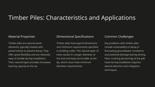


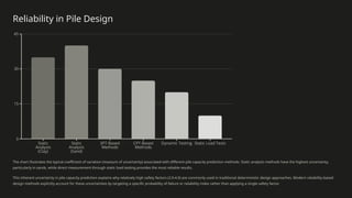
![Ultimate Static Pile Point Capacity
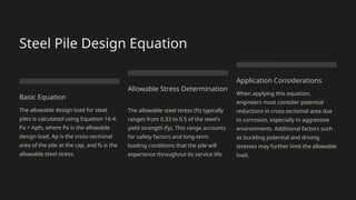
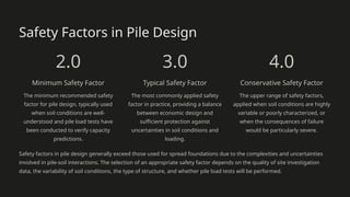
General Equation
The ultimate static pile point
capacity is calculated using
Equation 16-6: Ppu = Ap(cN'cdcsc +
qN'qdqsq + ½γ'BpNγsγ), where Ap
is the effective area of the pile
point, and the other terms
represent soil properties and
bearing capacity factors.
Simplified Form
For practical applications, a
simplified form is often used
(Equation 16-6a): Ppu = Ap[cN'cdc +
q(N'q-1)dq], which neglects the Nγ
term as its contribution is typically
small for deep foundations.
Cohesive Soils
For pure cohesive soils (φ = 0), the
equation simplifies further to
Equation 16-6b: Ppu = Ap(9su),
where su is the undrained shear
strength of the soil beneath the pile
tip.](https://image.slidesharecdn.com/sachpazisstaticpilecapacityanalysisanddesignlt-250309235535-30ab3d60/85/Sachpazis-Foundation-Analysis-and-Design-Single-Piles-19-320.jpg)
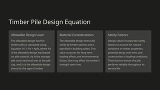
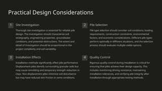
![Bearing Capacity Factors: Vesic Method
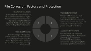
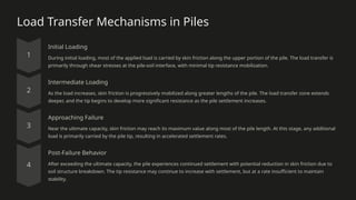
Cohesive Soils
For cohesive soils with internal
friction angle φ > 0, Vesic provides
Equation 16-7a: N'c = (Nq-1)cot φ to
calculate the bearing capacity factor
N'c.
1
Undrained Conditions
When undrained conditions apply (φ
= 0), Vesic suggests Equation 16-7b:
N'c = [1+⅔ln Irr]+1+⅔(π/2) for
calculating the bearing capacity
factor.
2
Rigidity Index
The reduced rigidity index Irr is
calculated using Equation 16-7c: Irr =
Ir/(1+evIr), where Ir is the rigidity
index and ev is the volumetric strain.
3
Shear Modulus Relation
The rigidity index Ir is determined
using Equation 16-7d: Ir = G'/(c+q tan
φ) = G'/s, where G' is the shear
modulus and s is the shear strength
of the soil.
4](https://image.slidesharecdn.com/sachpazisstaticpilecapacityanalysisanddesignlt-250309235535-30ab3d60/85/Sachpazis-Foundation-Analysis-and-Design-Single-Piles-20-320.jpg)
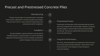
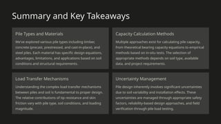
![Using Penetration Test Data for Pile Design
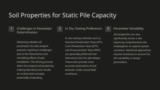
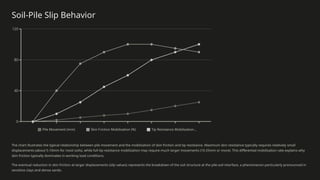
Standard Penetration Test
(SPT)
Meyerhof suggested using SPT data
to estimate pile capacity with
Equation 16-8: Ppu = Ap(40N)Lb/B ≤
Ap[38N(Lb/B)], where N is the SPT
blow count, Lb is the pile embedment
depth, and B is the pile width.
Cone Penetration Test (CPT)
CPT data provides more continuous
soil profile information and can be
directly correlated to pile capacity.
The cone resistance is particularly
useful for estimating both tip
resistance and skin friction along the
pile shaft.
Japanese Method
Shioi and Fukui (1982) proposed
Equation 16-9 for Japanese practice:
Ppu = quitAp, where quit is the
ultimate bearing pressure
determined from either Dutch or
Electric CPT cones or SPT tests.](https://image.slidesharecdn.com/sachpazisstaticpilecapacityanalysisanddesignlt-250309235535-30ab3d60/85/Sachpazis-Foundation-Analysis-and-Design-Single-Piles-21-320.jpg)


ρ. Κώστας Σαχπάζης: Foundation Analysis and Design: Single Piles Welcome to this comprehensive presentation on "Foundation Analysis and Design," focusing on Single Piles—Static Capacity, Lateral Loads, and Pile/Pole Buckling. This presentation will explore the fundamental concepts, equations, and practical considerations for designing and analyzing pile foundations. We'll examine different pile types, their characteristics, load transfer mechanisms, and the complex interactions between piles and surrounding soil. Throughout this presentation, we'll highlight key equations and methodologies for calculating pile capacities under various conditions.