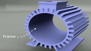
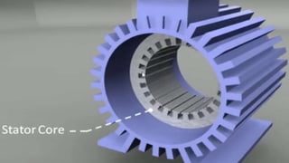
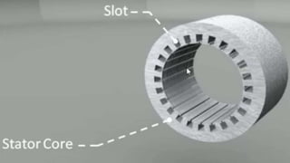
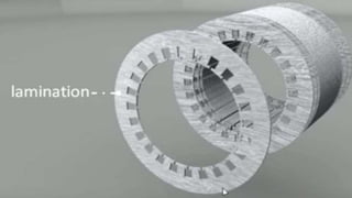
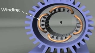
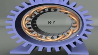
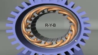
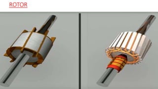
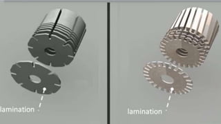
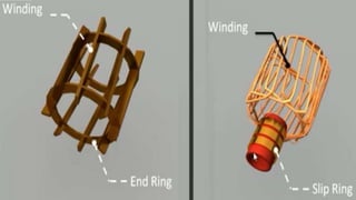
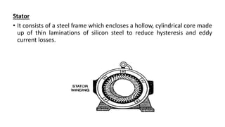
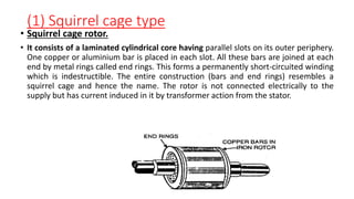
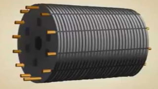
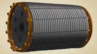
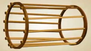
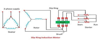
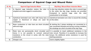
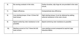
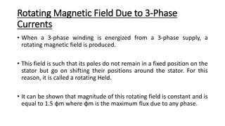
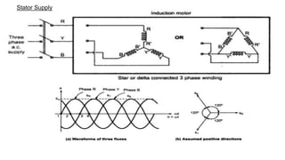
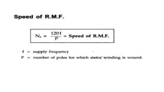
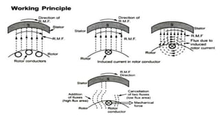
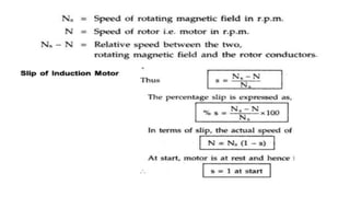
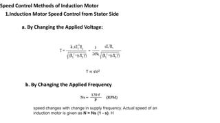
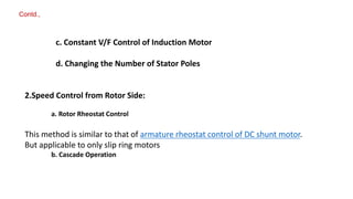
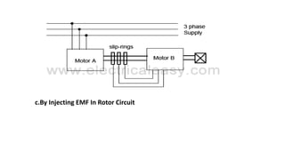
Three Phase Induction
Motors
CONTENTS
Three Phase Induction Motors:
• Construction- working principle
• Torque equation
• Torque-Slip characteristics.
• Speed Control Techniques
• The three-phase induction motors are the most widely used electric
motors in industry. They run at essentially constant speed from no-load
to full-load.
• However, the speed is frequency dependent and consequently these
motors are not easily adapted to speed control.
INTRODUCTION
Advantages
• It has simple and rugged construction.
• It is relatively cheap.
• It requires little maintenance.
• It has high efficiency and reasonably good power factor.
• It has self starting torque.
Disadvantages
• It is essentially a constant speed motor and its speed cannot be changed
easily.
• Its starting torque is inferior to d.c shunt motor.
Construction
• A 3-phase induction motor has two main parts (1) stator and (2) rotor.
• The rotor is separated from the stator by a small air-gap which ranges
from 0.4 mm to 4 mm, depending on the power of the motor.
R
R-Y
R-Y-B
ROTOR
Stator
• It consists of a steel frame which encloses a hollow, cylindrical core made
up of thin laminations of silicon steel to reduce hysteresis and eddy
current losses.
ROTOR
The rotor, mounted on a shaft, is a hollow
laminated core having slots on its outer periphery.
The winding placed in these slots (called rotor
winding) may be one of the following two types:
(1) Squirrel cage type (2) Wound type
(1) Squirrel cage type
• Squirrel cage rotor.
• It consists of a laminated cylindrical core having parallel slots on its outer periphery.
One copper or aluminium bar is placed in each slot. All these bars are joined at each
end by metal rings called end rings. This forms a permanently short-circuited winding
which is indestructible. The entire construction (bars and end rings) resembles a
squirrel cage and hence the name. The rotor is not connected electrically to the
supply but has current induced in it by transformer action from the stator.
(2) Wound type
• Wound rotor
• It consists of a laminated cylindrical core and carries a 3-phase winding,
similar to the one on the stator. The rotor winding is uniformly
distributed in the slots and is usually star-connected.
• The open ends of the rotor winding are brought out and joined to three
insulated slip rings mounted on the rotor shaft with one brush resting on
each slip ring. The three brushes are connected to a 3-phase star-
connected rheostat as shown in Fig. At starting, the external resistances
are included in the rotor circuit to give a large starting torque. These
resistances are gradually reduced to zero as the motor runs up to speed.
Wound type (slip ring induction motor)
Sr. No. Squirrel Cage Induction Motor Slip Ring / Wound Rotor Induction Motor
1) In Squirrel cage induction motors the rotor is
simplest and most rugged in construction.
In slip ring induction motors the rotor is wound type.
In the motor the slip rings, brushes are provided.
Compared to squirrel cage rotor the rotor
construction is not simple.
2) Cylindrical laminated core rotor with heavy bars or
copper or Aluminum or alloys are used for
conductors.
Cylindrical laminated core rotor is wound like winding
on the stator.
3) Rotor conductors or rotor bars are short circuited
with end rings.
At starting the 3 phase windings are connected to a
star connected rheostat and during running condition,
the windings are short circuited at the slip rings.
4) Rotor bars are permanently short circuited and
hence it is not possible to connect external
resistance in the circuit in series with the rotor
conductors.
It is possible to insert additional resistance in the
rotor circuit. Therefore it is possible to increase the
torque; the additional series resistance is used for
starting purposes.
5) Cheaper cost. Cost is slightly higher.
6) No moving contacts in the rotor. Carbon brushes, slip rings etc are provided in the rotor
circuit.
7) Higher efficiency. Comparatively less efficiency.
8) Low starting torque. It has 1.5 time full
load torque.
High starting torque. It can be obtained by adding
external resistance in the rotor circuit.
9) Speed control by rotor resistance is not
possible.
Speed control by rotor resistance is possible.
10) Starting current is 5 to 7 times the full
load current.
Less starting current compared to squirrel cage
Induction Motor.
Rotating Magnetic Field Due to 3-Phase
Currents
• When a 3-phase winding is energized from a 3-phase supply, a
rotating magnetic field is produced.
• This field is such that its poles do not remain in a fixed position on the
stator but go on shifting their positions around the stator. For this
reason, it is called a rotating Held.
• It can be shown that magnitude of this rotating field is constant and is
equal to 1.5 φm where φm is the maximum flux due to any phase.
Stator Supply
Numericals
Numericals
Numerical
Power Stages of 3-φ Induction Motor
Speed Control Methods of Induction Motor
1.Induction Motor Speed Control from Stator Side
a. By Changing the Applied Voltage:
T ∝ sV2
b. By Changing the Applied Frequency
speed changes with change in supply frequency. Actual speed of an
induction motor is given as N = Ns (1 - s). H
c. Constant V/F Control of Induction Motor
d. Changing the Number of Stator Poles
Contd.,
2.Speed Control from Rotor Side:
a. Rotor Rheostat Control
This method is similar to that of armature rheostat control of DC shunt motor.
But applicable to only slip ring motors
b. Cascade Operation
c.By Injecting EMF In Rotor Circuit
REFERENCES
https://www.youtube.com/watch?v=CL2YEx4ul80
https://www.youtube.com/watch?v=AQqyGNOP_3o
https://www.youtube.com/watch?v=JPn5Ou-N0b0
https://www.youtube.com/watch?v=QLvWGFD4Qyo
https://www.youtube.com/watch?v=MEoKTdJgf5s
https://www.youtube.com/watch?v=R9-TozphVmk
https://www.youtube.com/watch?v=LtJoJBUSe28

INDUCTION MOTORS (3).pptx

  • 1.
  • 2.
    CONTENTS Three Phase InductionMotors: • Construction- working principle • Torque equation • Torque-Slip characteristics. • Speed Control Techniques
  • 3.
    • The three-phaseinduction motors are the most widely used electric motors in industry. They run at essentially constant speed from no-load to full-load. • However, the speed is frequency dependent and consequently these motors are not easily adapted to speed control. INTRODUCTION
  • 4.
    Advantages • It hassimple and rugged construction. • It is relatively cheap. • It requires little maintenance. • It has high efficiency and reasonably good power factor. • It has self starting torque. Disadvantages • It is essentially a constant speed motor and its speed cannot be changed easily. • Its starting torque is inferior to d.c shunt motor.
  • 5.
    Construction • A 3-phaseinduction motor has two main parts (1) stator and (2) rotor. • The rotor is separated from the stator by a small air-gap which ranges from 0.4 mm to 4 mm, depending on the power of the motor.
  • 10.
  • 11.
  • 12.
  • 13.
  • 16.
    Stator • It consistsof a steel frame which encloses a hollow, cylindrical core made up of thin laminations of silicon steel to reduce hysteresis and eddy current losses.
  • 17.
    ROTOR The rotor, mountedon a shaft, is a hollow laminated core having slots on its outer periphery. The winding placed in these slots (called rotor winding) may be one of the following two types: (1) Squirrel cage type (2) Wound type
  • 18.
    (1) Squirrel cagetype • Squirrel cage rotor. • It consists of a laminated cylindrical core having parallel slots on its outer periphery. One copper or aluminium bar is placed in each slot. All these bars are joined at each end by metal rings called end rings. This forms a permanently short-circuited winding which is indestructible. The entire construction (bars and end rings) resembles a squirrel cage and hence the name. The rotor is not connected electrically to the supply but has current induced in it by transformer action from the stator.
  • 22.
    (2) Wound type •Wound rotor • It consists of a laminated cylindrical core and carries a 3-phase winding, similar to the one on the stator. The rotor winding is uniformly distributed in the slots and is usually star-connected. • The open ends of the rotor winding are brought out and joined to three insulated slip rings mounted on the rotor shaft with one brush resting on each slip ring. The three brushes are connected to a 3-phase star- connected rheostat as shown in Fig. At starting, the external resistances are included in the rotor circuit to give a large starting torque. These resistances are gradually reduced to zero as the motor runs up to speed.
  • 23.
    Wound type (slipring induction motor)
  • 26.
    Sr. No. SquirrelCage Induction Motor Slip Ring / Wound Rotor Induction Motor 1) In Squirrel cage induction motors the rotor is simplest and most rugged in construction. In slip ring induction motors the rotor is wound type. In the motor the slip rings, brushes are provided. Compared to squirrel cage rotor the rotor construction is not simple. 2) Cylindrical laminated core rotor with heavy bars or copper or Aluminum or alloys are used for conductors. Cylindrical laminated core rotor is wound like winding on the stator. 3) Rotor conductors or rotor bars are short circuited with end rings. At starting the 3 phase windings are connected to a star connected rheostat and during running condition, the windings are short circuited at the slip rings. 4) Rotor bars are permanently short circuited and hence it is not possible to connect external resistance in the circuit in series with the rotor conductors. It is possible to insert additional resistance in the rotor circuit. Therefore it is possible to increase the torque; the additional series resistance is used for starting purposes. 5) Cheaper cost. Cost is slightly higher.
  • 27.
    6) No movingcontacts in the rotor. Carbon brushes, slip rings etc are provided in the rotor circuit. 7) Higher efficiency. Comparatively less efficiency. 8) Low starting torque. It has 1.5 time full load torque. High starting torque. It can be obtained by adding external resistance in the rotor circuit. 9) Speed control by rotor resistance is not possible. Speed control by rotor resistance is possible. 10) Starting current is 5 to 7 times the full load current. Less starting current compared to squirrel cage Induction Motor.
  • 28.
    Rotating Magnetic FieldDue to 3-Phase Currents • When a 3-phase winding is energized from a 3-phase supply, a rotating magnetic field is produced. • This field is such that its poles do not remain in a fixed position on the stator but go on shifting their positions around the stator. For this reason, it is called a rotating Held. • It can be shown that magnitude of this rotating field is constant and is equal to 1.5 φm where φm is the maximum flux due to any phase.
  • 29.
  • 39.
  • 40.
  • 41.
  • 42.
    Power Stages of3-φ Induction Motor
  • 43.
    Speed Control Methodsof Induction Motor 1.Induction Motor Speed Control from Stator Side a. By Changing the Applied Voltage: T ∝ sV2 b. By Changing the Applied Frequency speed changes with change in supply frequency. Actual speed of an induction motor is given as N = Ns (1 - s). H
  • 44.
    c. Constant V/FControl of Induction Motor d. Changing the Number of Stator Poles Contd., 2.Speed Control from Rotor Side: a. Rotor Rheostat Control This method is similar to that of armature rheostat control of DC shunt motor. But applicable to only slip ring motors b. Cascade Operation
  • 45.
    c.By Injecting EMFIn Rotor Circuit
  • 46.