![www.heatflux.com
Flue Gas Flow and Temperature Profile
9
Higher
velocity flue
gas is
observed on
the inner side
Higher flue
gas
temperature
observed near
the inner cell
tubes
Existing Design
[°F]
[ft/s]](https://image.slidesharecdn.com/afrc-improvingperformanceofcokerheatersrev-200415172449/85/Improving-Performance-of-Coker-Heaters-9-320.jpg)
![www.heatflux.com
Radiant Heat Flux Profile
10
Radiant heat flux for
inner cell tubes is
higher as compared to
the outer cell tubes
Existing Design
Inner Tubes Outer Tubes
[Btu/hr.ft2]](https://image.slidesharecdn.com/afrc-improvingperformanceofcokerheatersrev-200415172449/85/Improving-Performance-of-Coker-Heaters-10-320.jpg)
![www.heatflux.com
Flue Gas Temperature around Tubes
11
[°F]
Inner Tubes Outer Tubes
Flue gas temperatures around
inner cell tubes and outer cell
tubes are significantly
different
Existing Design](https://image.slidesharecdn.com/afrc-improvingperformanceofcokerheatersrev-200415172449/85/Improving-Performance-of-Coker-Heaters-11-320.jpg)
![www.heatflux.com
[°F]
Flue Gas Flow and Temperature Profile
12
High flue gas temperature and
velocity is reduced for the inner
tubes
Existing Operating[ft/s]](https://image.slidesharecdn.com/afrc-improvingperformanceofcokerheatersrev-200415172449/85/Improving-Performance-of-Coker-Heaters-12-320.jpg)
![www.heatflux.com
Radiant Heat Flux
13
Inner Tubes Outer Tubes
Radiant heat flux is
similar for inner and
outer tubes for
operating case
Existing Operating
[Btu/hr.ft2]](https://image.slidesharecdn.com/afrc-improvingperformanceofcokerheatersrev-200415172449/85/Improving-Performance-of-Coker-Heaters-13-320.jpg)
![www.heatflux.com
Flue Gas Temperature around Tubes
Inner Tubes
Existing Operating
[°F]
Outer Tubes
Clearly, the difference in
flue gas temperatures around
inner and outer cell tubes
have reduced significantly as
compared to the design case
This reduction is because
inner cells were fired at 30%
lower firing rate than outer
cells
14](https://image.slidesharecdn.com/afrc-improvingperformanceofcokerheatersrev-200415172449/85/Improving-Performance-of-Coker-Heaters-14-320.jpg)
![www.heatflux.com
Flue Gas Temperature Profile
17
Operating Case
For operating case flue
gas temperature in the
inner cell has reduced
[°F]
Design Case](https://image.slidesharecdn.com/afrc-improvingperformanceofcokerheatersrev-200415172449/85/Improving-Performance-of-Coker-Heaters-17-320.jpg)
![www.heatflux.com
Radiant Heat Flux Profile
18
Design Case Operating Case
Radiant tubes heat flux
for inner tubes has
been reduced for the
operating case
[Btu/hr.ft2]](https://image.slidesharecdn.com/afrc-improvingperformanceofcokerheatersrev-200415172449/85/Improving-Performance-of-Coker-Heaters-18-320.jpg)
![www.heatflux.com
Velocity Vectors
Flue gas velocity near inner
tubes is very high and getting
deflected downward
Flue gas velocity is shifted
downward with addition of baffle
Roof tubes are away from flue gas
Adding refractory baffle at the top further improves the flue gas recirculation pattern
Existing Proposed Case with
Baffle
Proposed Case
[ft/s]](https://image.slidesharecdn.com/afrc-improvingperformanceofcokerheatersrev-200415172449/85/Improving-Performance-of-Coker-Heaters-23-320.jpg)
![www.heatflux.com
Flue Gas Temperature Contours
Addition of refractory baffle further increased the distance of hot flue gas with
respect to roof tubes
High temperature flue gas is
touching the inner roof tubes
Shifting roof tubes reduces chances of
flame impingement / coking issues
24
[°F]
Existing Proposed Case with
Baffle
Proposed Case](https://image.slidesharecdn.com/afrc-improvingperformanceofcokerheatersrev-200415172449/85/Improving-Performance-of-Coker-Heaters-24-320.jpg)
![www.heatflux.com
Radiant Tube Heat Flux (Arch)
Maximum heat flux on roof tubes is reduced by ~4,200 Btu/hr.ft2
Proposed Case
Heat Flux 18,651 Btu/hr.ft2 Heat Flux 14,443 Btu/hr.ft2
Existing
25
[Btu/hr.ft2]](https://image.slidesharecdn.com/afrc-improvingperformanceofcokerheatersrev-200415172449/85/Improving-Performance-of-Coker-Heaters-25-320.jpg)
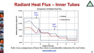
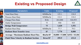
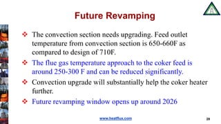


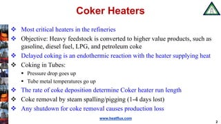
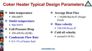
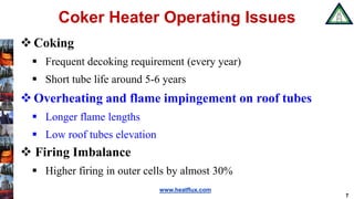
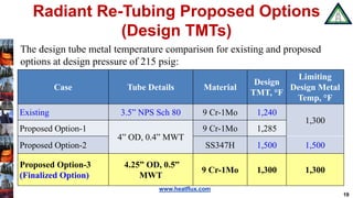
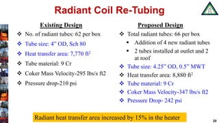
The document discusses improvements to coker heaters critical for converting heavy feedstock in refineries to valuable products like gasoline and diesel fuel. It outlines design parameters, operating issues, and proposes a new radiant coil re-tubing design to enhance performance and reduce overheating. Future upgrades to the convection section are suggested to further optimize heater efficiency in a planned revamping around 2026.


![Kbr[1] report](https://cdn.slidesharecdn.com/ss_thumbnails/kbr1-160104072613-thumbnail.jpg?width=640&height=640&fit=bounds)