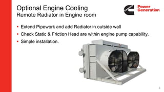
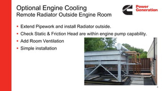
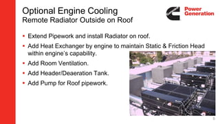
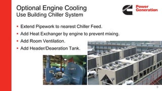
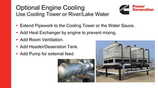
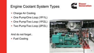
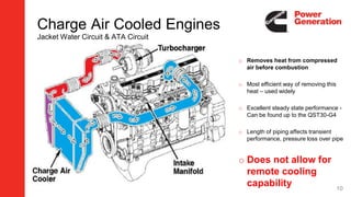
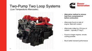
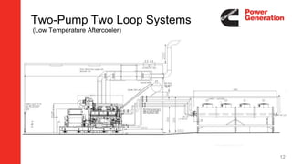
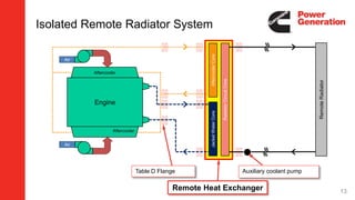
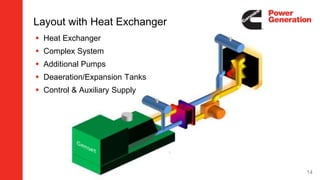
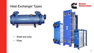
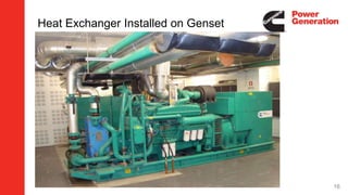
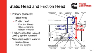
Remote Cooling
Applications
This session…
 Remote Cooling Packages
 Engine Cooling Configurations
 Heat Exchangers & Dearation
 Static and Friction Head
 Room Cooling and Ventilation
2
Optional Engine Cooling
Remote Radiator in Engine room
 Extend Pipework and add Radiator in outside wall
 Check Static & Friction Head are within engine pump capability.
 Simple installation.
3
Optional Engine Cooling
Remote Radiator Outside Engine Room
 Extend Pipework and install Radiator outside.
 Check Static & Friction Head are within engine pump capability.
 Add Room Ventilation
 Simple installation
4
Optional Engine Cooling
Remote Radiator Outside on Roof
 Extend Pipework and install Radiator on roof.
 Add Heat Exchanger by engine to maintain Static & Friction Head
within engine’s capability.
 Add Room Ventilation.
 Add Header/Deaeration Tank.
 Add Pump for Roof pipework.
5
Optional Engine Cooling
Use Building Chiller System
 Extend Pipework to nearest Chiller Feed.
 Add Heat Exchanger by engine to prevent mixing.
 Add Room Ventilation.
 Add Header/Deaeration Tank.
6
Optional Engine Cooling
Use Cooling Tower or River/Lake Water
 Extend Pipework to the Cooling Tower or the Water Sauce.
 Add Heat Exchanger by engine to prevent mixing.
 Add Room Ventilation.
 Add Header/Deaeration Tank.
 Add Pump for external feed.
7
Remote Cooling Applications
So how do we make it work?
8
 Charge Air Cooling
 One Pump/One Loop (1P/1L)
 One Pump/Two Loop (1P/2L)
 Two Pump/Two Loop (2P/2L)
And do not forget..
 Fuel Cooling
Engine Coolant System Types
9
Charge Air Cooled Engines
Jacket Water Circuit & ATA Circuit
o Removes heat from compressed
air before combustion
o Most efficient way of removing this
heat – used widely
o Excellent steady state performance -
Can be found up to the QST30-G4
o Length of piping affects transient
performance, pressure loss over pipe
o Does not allow for
remote cooling
capability 10
11
Two-Pump Two Loop Systems
(Low Temperature Aftercooler)
o Alternative method to remove
heat from compressed air
before combustion
o Aftercooler found on side of
engine, filled with coolant
o Aftercooler chilled by LTA core on
radiator – typically 27 deg C
o Found on larger engines, remote
cooling possible
o Much better transient performance
Two-Pump Two Loop Systems
(Low Temperature Aftercooler)
12
Isolated Remote Radiator System
Aftercooler
Engine
Air
Air
AftercoolerCoreJacketWaterCore
RadiatorCircuitCore
RemoteRadiator
Aftercooler
Table D Flange
Remote Heat Exchanger
Auxiliary coolant pump
13
14
 Heat Exchanger
 Complex System
 Additional Pumps
 Deaeration/Expansion Tanks
 Control & Auxiliary Supply
Layout with Heat Exchanger
15
Heat Exchanger Types
• Shell and tube
• Plate
Heat Exchanger Installed on Genset
16
 Primary concerns:
– Static head
– Friction head
• Pipe size, # bends
• Other components
• Radiator restriction
 If either exceeded, isolated
cooling system required
 Note other system features
– Isolation, fittings.
– multi-loop systems
Static
Head
Friction
Head
Static Head and Friction Head
17
Static Head and Friction Head
 Calculate pump pressure requirements
– Pressure drop across remote radiator
– Pressure drop due to coolant pipes
 Compare engine pump friction head limitations
– If out of spec: weigh cost of increasing pipe size vs adding auxiliary
pump
 Determine remote radiator coolant static head
 Compare to engine static head limitations
– If out of spec: design for isolated system
18
Deaeration Tanks
 Allows air in coolant to escape.
 Allows for expansion of coolant.
 Allows additional coolant
volume for system drawdown
 Applies to set mounted and
remotely cooled systems
Engine
19
Deaeration Tanks
Tank must always be Installed at highest point in the system.
Top Tank
Remote
Radiator
/Cooler
Coolant Line from remote
Radiator to Coolant pump
Coolant Line from
engine/aftercooler
to remote
Radiator
Vent Line
Pressure Cap/Valve
A
B
C
Thermostat
Housing/Coolant out
Coolant Pump Inlet
Cooling System vent
connection Point(s)
A. Top tank to provide
recommended
drawdown capacity.
B.Expansion space
sized by depth of
neck extension into
tank. Vent hole near
top of tank in side of
neck.
C.Tank Fill line 19 mm
(3/4 in) minimum to
provide positive head
to the pump suction.
Overflow Tube
Vent Hole
Vent Line
20
Deaeration Pipes & Tanks
21
Avoid Air Entrapment
 Route fill line/make-up line upstream of water pump
 Avoid air traps in piping/vent lines
22
Deaeration Tanks
 Should hold minimum of 11% of total coolant volume
for system drawdown
 Thermal expansion volume = at least 6% of total
system volume
 Most 2P2L systems utilize a common tank
(exception being some stationary natural gas units)
– Mixing of LT and HT coolant streams is acceptable because of
minimal volume being transferred to LT through make-up fill line
23
Auxiliary Fan for Room Ventilation
Cool Air
Flow In
Radiator
Air Inlet
Louvers
Room Ventilation
Fan
Room ventilation fans provide the necessary vacuum to pull air into the room and across the genset.
It is often beneficial to include an auxiliary fan in set mounted radiators as well to cool the room and
genset after the unit has shutdown. The hot surfaces of the machine will continue to reject heat to
the room and in most cases without a shutdown ventilation fan provision, the room temperature will
rise AFTER the unit is off.
24
Ventilation System Design
Outlet
Inlet
Recommended
(for remote cooling only)
Not Acceptable
OutletInlet
 Airflow is required through genset room for…
 Radiant heat from hot engine parts
 Engine air intake
 Alternator Cooling 25
26
a) Determine heat rejection to ambient room (Qtotal)
• Include engine, alternator, muffler, exhaust piping, auxiliary
items.
b) Maximum allowable temperature rise
• ∆𝑇 𝑚𝑎𝑥 = 𝑀𝑎𝑥. 𝑅𝑜𝑜𝑚𝑇𝑒𝑚𝑝. −𝑀𝑎𝑥. 𝐴𝑚𝑏𝑖𝑒𝑛𝑡𝑇𝑒𝑚𝑝.
c) Calculate cooling airflow required (Qroom)
• 𝑉𝑟𝑜𝑜𝑚 =
𝑄 𝑡𝑜𝑡𝑎𝑙
𝐶 𝑝×∆𝑇 𝑚𝑎𝑥×𝑑
d) Calculate total room airflow requirement (Qroom)
• 𝑉𝑡𝑜𝑡𝑎𝑙 = 𝑉𝑟𝑜𝑜𝑚 + 𝑉𝑐𝑜𝑚𝑏𝑢𝑠𝑡𝑖𝑜𝑛
e) In case of need compensate for density changes due
to altitude
• For every 305 meters increase air flow by 3%
Key
Vroom= minimum forced ventilation
airflow (m3/min)
Qtotal = total heat emitted to room
(MJ/min)
Cp = specific heat
(1.01x10⁻³ MJ/kg/oC)
∆T = Generator set room
temperature rise (oC)
D = density of air (1.20 kg/m3)
Determining Airflow Requirements
Cold Weather Climates
 Motorized Louvers
closed while genset is
off.
 Recirculation dampers
to warm room quickly
 Room heaters
– Anti-condensation
– Space heaters
– Lube/Fuel Oil heaters
– Battery heater
– Control panel heaters
27
CPG Additional features
 55 degC radiators for specific applications.
 Two speed radiator fans for noise reduction.
 Tin Core radiators suited for saline environments
 Special design fins for sandy or dusty conditions
 Vertical and horizontal (flat-bed) remote radiators
 Remote Heat Exchangers
 Fuel coolers
28
29
Any Questions?
Cooling System Capability Ratings
 Limiting Ambient Temperature is measured via a combination of test
and simulation of the genset and cooling package.
– Reflects actual operating conditions
 Air on Core Temperature is measured with only the radiator itself.
– Does not reflect operating conditions
– Genset blocks a sizeable portion of the airflow
– Does not account for the temperature rise across the genset.
– Can also be misleading, as a customer may not check where the temperature is
measured and plan for a higher than capable ambient
30

3. remote cooling applications

  • 1.
  • 2.
    This session…  RemoteCooling Packages  Engine Cooling Configurations  Heat Exchangers & Dearation  Static and Friction Head  Room Cooling and Ventilation 2
  • 3.
    Optional Engine Cooling RemoteRadiator in Engine room  Extend Pipework and add Radiator in outside wall  Check Static & Friction Head are within engine pump capability.  Simple installation. 3
  • 4.
    Optional Engine Cooling RemoteRadiator Outside Engine Room  Extend Pipework and install Radiator outside.  Check Static & Friction Head are within engine pump capability.  Add Room Ventilation  Simple installation 4
  • 5.
    Optional Engine Cooling RemoteRadiator Outside on Roof  Extend Pipework and install Radiator on roof.  Add Heat Exchanger by engine to maintain Static & Friction Head within engine’s capability.  Add Room Ventilation.  Add Header/Deaeration Tank.  Add Pump for Roof pipework. 5
  • 6.
    Optional Engine Cooling UseBuilding Chiller System  Extend Pipework to nearest Chiller Feed.  Add Heat Exchanger by engine to prevent mixing.  Add Room Ventilation.  Add Header/Deaeration Tank. 6
  • 7.
    Optional Engine Cooling UseCooling Tower or River/Lake Water  Extend Pipework to the Cooling Tower or the Water Sauce.  Add Heat Exchanger by engine to prevent mixing.  Add Room Ventilation.  Add Header/Deaeration Tank.  Add Pump for external feed. 7
  • 8.
    Remote Cooling Applications Sohow do we make it work? 8
  • 9.
     Charge AirCooling  One Pump/One Loop (1P/1L)  One Pump/Two Loop (1P/2L)  Two Pump/Two Loop (2P/2L) And do not forget..  Fuel Cooling Engine Coolant System Types 9
  • 10.
    Charge Air CooledEngines Jacket Water Circuit & ATA Circuit o Removes heat from compressed air before combustion o Most efficient way of removing this heat – used widely o Excellent steady state performance - Can be found up to the QST30-G4 o Length of piping affects transient performance, pressure loss over pipe o Does not allow for remote cooling capability 10
  • 11.
    11 Two-Pump Two LoopSystems (Low Temperature Aftercooler) o Alternative method to remove heat from compressed air before combustion o Aftercooler found on side of engine, filled with coolant o Aftercooler chilled by LTA core on radiator – typically 27 deg C o Found on larger engines, remote cooling possible o Much better transient performance
  • 12.
    Two-Pump Two LoopSystems (Low Temperature Aftercooler) 12
  • 13.
    Isolated Remote RadiatorSystem Aftercooler Engine Air Air AftercoolerCoreJacketWaterCore RadiatorCircuitCore RemoteRadiator Aftercooler Table D Flange Remote Heat Exchanger Auxiliary coolant pump 13
  • 14.
    14  Heat Exchanger Complex System  Additional Pumps  Deaeration/Expansion Tanks  Control & Auxiliary Supply Layout with Heat Exchanger
  • 15.
    15 Heat Exchanger Types •Shell and tube • Plate
  • 16.
  • 17.
     Primary concerns: –Static head – Friction head • Pipe size, # bends • Other components • Radiator restriction  If either exceeded, isolated cooling system required  Note other system features – Isolation, fittings. – multi-loop systems Static Head Friction Head Static Head and Friction Head 17
  • 18.
    Static Head andFriction Head  Calculate pump pressure requirements – Pressure drop across remote radiator – Pressure drop due to coolant pipes  Compare engine pump friction head limitations – If out of spec: weigh cost of increasing pipe size vs adding auxiliary pump  Determine remote radiator coolant static head  Compare to engine static head limitations – If out of spec: design for isolated system 18
  • 19.
    Deaeration Tanks  Allowsair in coolant to escape.  Allows for expansion of coolant.  Allows additional coolant volume for system drawdown  Applies to set mounted and remotely cooled systems Engine 19
  • 20.
    Deaeration Tanks Tank mustalways be Installed at highest point in the system. Top Tank Remote Radiator /Cooler Coolant Line from remote Radiator to Coolant pump Coolant Line from engine/aftercooler to remote Radiator Vent Line Pressure Cap/Valve A B C Thermostat Housing/Coolant out Coolant Pump Inlet Cooling System vent connection Point(s) A. Top tank to provide recommended drawdown capacity. B.Expansion space sized by depth of neck extension into tank. Vent hole near top of tank in side of neck. C.Tank Fill line 19 mm (3/4 in) minimum to provide positive head to the pump suction. Overflow Tube Vent Hole Vent Line 20
  • 21.
  • 22.
    Avoid Air Entrapment Route fill line/make-up line upstream of water pump  Avoid air traps in piping/vent lines 22
  • 23.
    Deaeration Tanks  Shouldhold minimum of 11% of total coolant volume for system drawdown  Thermal expansion volume = at least 6% of total system volume  Most 2P2L systems utilize a common tank (exception being some stationary natural gas units) – Mixing of LT and HT coolant streams is acceptable because of minimal volume being transferred to LT through make-up fill line 23
  • 24.
    Auxiliary Fan forRoom Ventilation Cool Air Flow In Radiator Air Inlet Louvers Room Ventilation Fan Room ventilation fans provide the necessary vacuum to pull air into the room and across the genset. It is often beneficial to include an auxiliary fan in set mounted radiators as well to cool the room and genset after the unit has shutdown. The hot surfaces of the machine will continue to reject heat to the room and in most cases without a shutdown ventilation fan provision, the room temperature will rise AFTER the unit is off. 24
  • 25.
    Ventilation System Design Outlet Inlet Recommended (forremote cooling only) Not Acceptable OutletInlet  Airflow is required through genset room for…  Radiant heat from hot engine parts  Engine air intake  Alternator Cooling 25
  • 26.
    26 a) Determine heatrejection to ambient room (Qtotal) • Include engine, alternator, muffler, exhaust piping, auxiliary items. b) Maximum allowable temperature rise • ∆𝑇 𝑚𝑎𝑥 = 𝑀𝑎𝑥. 𝑅𝑜𝑜𝑚𝑇𝑒𝑚𝑝. −𝑀𝑎𝑥. 𝐴𝑚𝑏𝑖𝑒𝑛𝑡𝑇𝑒𝑚𝑝. c) Calculate cooling airflow required (Qroom) • 𝑉𝑟𝑜𝑜𝑚 = 𝑄 𝑡𝑜𝑡𝑎𝑙 𝐶 𝑝×∆𝑇 𝑚𝑎𝑥×𝑑 d) Calculate total room airflow requirement (Qroom) • 𝑉𝑡𝑜𝑡𝑎𝑙 = 𝑉𝑟𝑜𝑜𝑚 + 𝑉𝑐𝑜𝑚𝑏𝑢𝑠𝑡𝑖𝑜𝑛 e) In case of need compensate for density changes due to altitude • For every 305 meters increase air flow by 3% Key Vroom= minimum forced ventilation airflow (m3/min) Qtotal = total heat emitted to room (MJ/min) Cp = specific heat (1.01x10⁻³ MJ/kg/oC) ∆T = Generator set room temperature rise (oC) D = density of air (1.20 kg/m3) Determining Airflow Requirements
  • 27.
    Cold Weather Climates Motorized Louvers closed while genset is off.  Recirculation dampers to warm room quickly  Room heaters – Anti-condensation – Space heaters – Lube/Fuel Oil heaters – Battery heater – Control panel heaters 27
  • 28.
    CPG Additional features 55 degC radiators for specific applications.  Two speed radiator fans for noise reduction.  Tin Core radiators suited for saline environments  Special design fins for sandy or dusty conditions  Vertical and horizontal (flat-bed) remote radiators  Remote Heat Exchangers  Fuel coolers 28
  • 29.
  • 30.
    Cooling System CapabilityRatings  Limiting Ambient Temperature is measured via a combination of test and simulation of the genset and cooling package. – Reflects actual operating conditions  Air on Core Temperature is measured with only the radiator itself. – Does not reflect operating conditions – Genset blocks a sizeable portion of the airflow – Does not account for the temperature rise across the genset. – Can also be misleading, as a customer may not check where the temperature is measured and plan for a higher than capable ambient 30

Editor's Notes

  • #11 We have both JWC & ATA circuit Purpose of the ATA is to remove heat from compressed air before combustion Turbocharge – turbine driven by exhaust gases, connected to compressor Air through air filters – compressed – more fuel 1m3 air – squeeze down, laws of physics tell us that we have a temp rise – 30degC to 150degC We need to get rid of this heat, hot air could cause pre ignition Air passed through charge air cooler – essentially an air to air radiator Cools down to eg 27deg C before into engine Most efficient, good steady state No remote cooling, poor transients
  • #12 Alternative method to remove heat from compressed air Ignore two stage turbo – focus on red aftercooler After cooler filled with coolant, chilled by LTA core – typically @ 27degC Air compressed, passed through aftercooler, straight into cylinders Notice much shorter pipe length – better transients, better at dealing with sudden load changes – large motors Found on larger engine – qsk95, kta50 etc
  • #14 Here is an example of an isolated remote radiator system. In this diagram, the jacket water and aftercooler coolant are on separate fluid circuits, although a one pump two loop system could also be used. These fluid flow through heat exchanger cores in a remote heat exchanger which is usually not far from the genset. The heat is transferred into an isolated remote radiator loop that makes the long run out to a remote radiator. This isolated loop is powered by an auxiliary coolant pump, which reduces stress on the engine’s own coolant pump.
  • #16 Shell and Tube Plate
  • #21 Deaeration tanks are also called “top tanks” because they are normally located on top of the radiator. They must be situated at the highest point in the system to prevent coolant from freely flowing into them under the force of gravity. A deaeration tank should always be fitted with a pressure cap to allow pressure to escape in the case of a boil-over. Without the cap, unusually high pressure could damage other parts of the system. The cooling system is generally filled and topped off with coolant from the deaeration tank. It is advantageous to fill the system at this point to avoid air bubble entrainment. The tanks usually have a sight glass, which allows for easy determination of the coolant level. The tanks should be sized for 17% of the total volume of the cooling system. This allows 6% to account for the thermal expansion of the coolant and 11% for drawdown. Drawdown is the capacity that can be lost by slow, undetected leaks. Deaeration tanks are also termed as “top tanks” since they normally sit on top of the radiator (usually the highest point in the system, it provides a convenient place for it) Pressure cap prevents damage to radiator core and flex lines from blowing out due to high pressure Filling from the deaeration tank makes logical sense since it is the highest point in the system as long as there is a fill line from the tank to the lowest point in the system Sight glass… if the top tank is dry, you don’t have enough coolant to complete the loop Drawdown: Amount of coolant that can be lost from the system before the coolant pump begins to draw air instead of coolant
  • #22 Route fill line/make-up line upstream of water pump (Low point in system). When venting to the top tank is not possible, atmospheric vents may need to be used. These lose significantly more coolant than a closed system Top tank volume needs to be increased (to ~14%) Avoid air traps in piping/vent lines Common air traps:
  • #25 Here is a diagram that shows room ventilation airflow for a remotely cooled genset. Electric fans can cool the room when the genset is running, and continue to cool the room after the genset has shut off.
  • #26 Hot spots can damage equipment. Critical to manage vacuum pressure within room Locate intake and discharge fans to distribute airflow evenly across genset Never locate exhaust components within 1’ of combustible materials or sprinkler heads. Never have the intake and exhaust louvers adjoining or even in close proximity Consider prevailing winds when locating radiator exhaust outlets The following rules apply to the ducting of heated engine air out of a building: Whenever possible, use no ductwork at all. Simply position the inlet air duct so that air will be drawn directly over the generator and expelled horizontally to the building exterior (outdoors). If duct work must be used between the generator installation location and the building air outlet opening, keep such ductwork as short as possible with a minimum number of bends. Construct air outlet duct work of self-supported sheet metal. Never locate the air outlet opening of a structure close to adjacent buildings or walls as noise is amplified when air is expelled in large volumes. Rules of Thumb: Intake: 1.5 x radiator core size for “Effective Open Area” Discharge: 1 x radiator core size for “Effective Open Area” Independently powered ventilation fans may be required to move air through room
  • #28 Dampers Divert a portion of discharge airflow back into room to increase ambient temperature Containerized genset with Climate Control Fuel oil waxing
  • #31 Limiting ambient temperature is measured in a test and simulation of the genset and cooling package. This rating reflects the capability of the cooling system under operating conditions. Air on Core temperatures are measured solely based on radiator performance. These tests do not reflect operating conditions, as the presence of the genset complicates airflow patterns over the radiator. Nor does it account for the temperature rise across genset components. This specification can be misleading to customers who would believe that the temperature rating is the environmental temperature at which the genset may be operated.