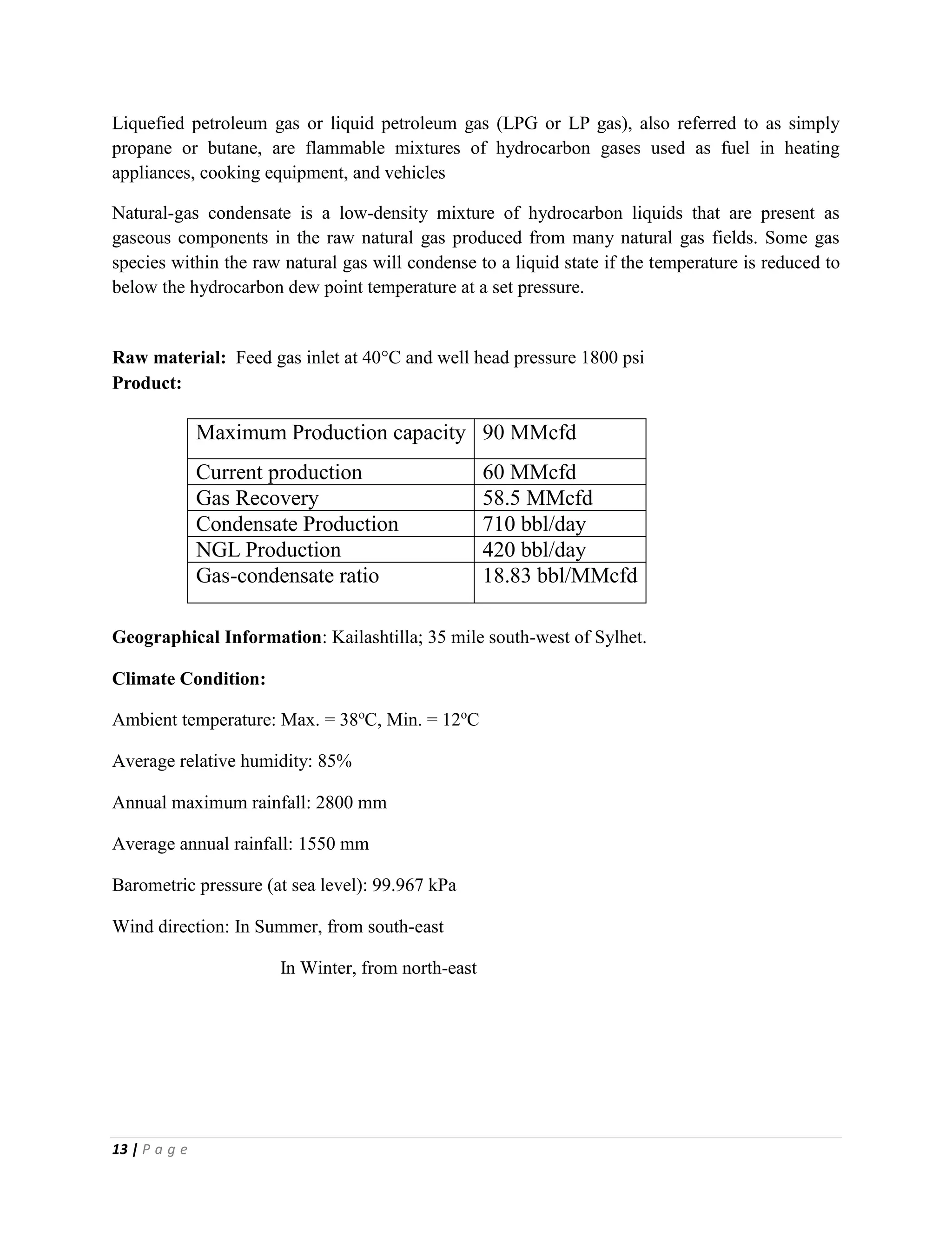
SlideShare a Scribd company logo
1 of 49
Download to read offline
1 | P a g e
Group Members
• Tanvir Ahmed 2011332005
• Iftekhar Hussain Chowdhury 2011332007
• Sabiha Akter 2011332019
• Md. Shahedul Haque 2011332024
• Md. Foridur Rahman Shishir 2011332038
• Israt Jahan 2011332039
• Khaliquzzaman Choudhury 2011332048
• Sainte Chakma 2011332052
• Sadia Begum 2011332058
• Tanmoy Das 2010332018
2 | P a g e
Contents
Page No.
Acknowledgement 4
Abstract 5
Chapter- I: Introduction 7-10
I.1 Plant Definition & Objectives
I.2 Definition of Natural Gas
I.3 Classification of natural gas
I.4 Key Definitions & Composition of NG
Chapter- II: Design Basis & Selection of Process 12-17
II.1 Design basis
II.2 Selection of Process
III.3 Comparison among process
Chapter- III: Process Description 19-26
III.1 Necessity of Natural Gas Processing
III.2 Process Description
III.3 MSTE Plant Units
III.4 Liquid Hydrocarbon (Condensate) Processing
Chapter- IV: Utilities 29-30
IV.1 Utilities of the Plant
3 | P a g e
Chapter- V: Plant Control System 32-33
Chapter- VI: Material & Energy Balance
Chapter- VII: In Plant Safety 35-40
VII.1 Plant Safety Issues
VII.2 Hazards in Plant
VII.3 Hazard Mitigation Planning & Prevention
Chapter- VIII: Economic Analysis 42-46
VIII.1 Cost Estimation
VIII.2 Cash Flow for Plant Operation
VIII.3 Capital Investment
VIII.4 Plant Income Summary
VIII.5 Return on Investment
VIII.6 Plant Total Cash flow Summary
Plant Layout 47
Conclusion 48
References 49
4 | P a g e
Acknowledgement
At first we are grateful to our Almighty Creator who is most beneficent and
merciful. We would like to thank our head of our department, Professor Dr. Md
Mastabur Rahman for granting us permission to perform this plant visit. We
express our deepest and profound respect to our supervisors Prof. Dr. Salma
Akhter and Rahatun Akter. We are indebted to them for helping us by providing
the necessary guidance, encouragement, valuable suggestions, strong inspection
and advice to perform the work successfully. We give special thanks to Md. Abul
Bashar & DGM of the Kailashtilla gas field for helping us on our site visit and
completing it without any obstacles. We also want to thank all the people of
Kailashtilla Gas Field Ltd. for their assistance, encouragement and support.
5 | P a g e
Abstract
Bangladesh has a lot of natural resources. Natural gas is the main geo resource
among them. Natural gas of our country is unique in the world for its quality.
Addition to this a lot amount of condensate is extracted in gas processing plants. In
our country the exploration processing and distributing are co-ordinated by the
Bangladesh Oil gas & Mineral Corporation. It has different companies for different
purposes. A number of associated foreign companies are also participating in this
sector. The industrial and power sector of Bangladesh has a great dependency on
the natural gas either for fuel or for raw material. The processed gas is also used in
domestic purpose and nowadays in vehicles as fuel.
This work includes natural gas processing and also how the processing plant works
(i.e. both the structural and functional aspects). The chapters deal with process
description of SGFL, Safety maintenance, fractionation, Laboratory analysis etc.
Details of molecular sieve in Kailashtilla gas fields have been discussed. The
purpose of the de-ethanizer is to separate by fractionation the methane and ethane
components contained in the feed. A de-ethanizer is designed for an assumed feed
composition.
6 | P a g e
Chapter I:
Introduction
7 | P a g e
I.1 Plant Definition & Objectives
A natural gas processing plant is a facility designed to process raw natural gas by separating
impurities and various non-methane hydrocarbons and fluids to produce what is known as
pipeline quality dry natural gas.
The objective of the project is to design a natural gas processing plant located at Kailashtilla,
Sylhet in Bangladesh, with a production capacity of 21900 MMCF per year, corresponding to a
daily production of 60 MMCFD, and 400 from 420 barrels of NGLs and 650 to 750 barrels of
condensate with sales gas, as by-product, including all offsite auxiliaries, utilities and support
facilities using natural gas as feed.
I.2 Definition of Natural Gas
Natural gas is a mixture of Methane, ethane, propane, butane, pentane, carbon dioxide, Nitrogen
etc. is the most important fuel belonging to this class & is found mainly in the vicinity of coal
mines or oil fields. The natural gas is also found associated with petroleum in Nature. It is not
only used as fuel or domestic or industrial purposes but also used as a chemical raw material for
various syntheses. Most of the natural gas used as fuel is derived from oil fields. However
sometimes the gas evaporated from the oil & diffused through rocks is trapped by impervious
dome shaped structure which may be far off from the original oil deposit. This constitutes a gas
field which may be under high pressure. Due to earth movement or pressure it may suddenly
escape out through fissure. This may result in ignition on its emergence to the atmosphere,
because of the static electricity produced by the rushing gas or because of increased temperatures
caused by friction. This gas is collected from the mine by drilling well & after some processing it
reaches to the consumers.
The global use of natural gas is growing rapidly. This is primarily attributed to the environmental
advantages it enjoys over other fossil fuels such as oil and coal. There is worldwide drive
towards increasing the utilization of natural gas and the need to minimize energy consumption
and increase profit associated with the process. These objectives can be achieved by reducing
time required to get products to market, increasing the quantity and quality of product produced
and designing plants for an optimum performance along their life cycle.
In Bangladesh this resource is controlled by the Bangladesh Oil gas & mineral Corporation
(PetroBangla). It has different departments to control different sections.
8 | P a g e
I.2 Classification of Natural Gas
The natural gas derived from wells are divided into three types, according to consisting of
different kinds of Hydrocarbon.
1. Dry Gas: If the lower hydrocarbons like methane ethane etc. are present at large amount
& small amount of water in well gas is called dry gas.
2. Wet Gas: If higher hydrocarbons are present with natural gas then it is called wet gas. It
is also called “marsh gas”.
I.3 Key Definitions & Composition of NG
Methane:
Methane is the predominant component of natural gas typically forming of 70% -99% of bulk
gas. It is colorless, odorless flammable gas. It is chemically inactive sparingly soluble in water &
is lighter than air.
Condensate:
It refers to the portion which condenses and separates out from NG as liquids when the gas is
produced at the surface. This liquid is composed of heavier hydrocarbon that exists as vapor
dissolved in NG in underground pressure temperature condition but turned to liquid at the
surface wellhead condition. Condensate is a valuable product & is processed to use commercially
as fuel.
Natural Gas Liquids (NGL):
NGL refers to a mixture of all hydrocarbons except methane which can be extracted by
compression and cooling in separator. After extraction NGL is distilled to be separated into
ethane, propane, butane & natural gasoline.
Liquefied Petroleum Gas (LPG):
LPG refers to mixture of essentially propane and butane which is extracted from wet natural gas.
LPG is also available during of crude oil. It is used as fuel to run automobiles.
Liquefied Natural Gas (LNG):
LNG refers to liquid form of natural gas that is produced by special liquefaction process in a
plant surface. LNG is suitable for transportation.
9 | P a g e
Compressed Natural Gas (CNG):
It refers to the NG made available in compressed form for the use as fuel in vehicles. Usually
NG is compressed to 300 pounds per square inch gauge in refining station and put in cylinder for
CNG run vehicles cooling the gas to 160o
C.
10 | P a g e
Table I.3-1: Constituents of Natural Gas
Components Amount (%) Pie-Chart
Methane 0.931
Ethane 0.03
Propane 0.007
i-Butane 0.0028
n-Butane 0.0028
i-Pentane 0.0025
n-Pentane 0.0023
n-Hexane 0.0022
n-Heptane 0.002
n-Octane 0.0018
n-Nonane 0.0015
n-Decane 0.0011
n-C11 0.0009
n-C12 0.0007
n-C13 0.0005
H2O 0.0109
Methane
Ethane
Propane
i-Butane
n-Butane
i-Pentane
n-Pentane
n-Hexane
n-Heptane
n-Octane
11 | P a g e
Chapter II:
Design Basis &
Selection of Process
12 | P a g e
II.1 Design Basis
Natural gas is considered 'dry' when it is almost pure methane, having had most of the other
commonly associated hydrocarbons removed. When other hydrocarbons are present, the natural
gas is 'wet'. Raw natural gas comes primarily from any one of three types of wells: crude oil
wells, gas wells, and condensate wells.
Crude oil wells—raw natural gas that comes from crude oil wells is called associated gas. This
gas can exist separate from the crude oil in the underground formation, or dissolved in the crude
oil. Condensate produced from oil wells is often referred to as lease condensate.
Dry gas wells—these wells typically produce only raw natural gas that does not contain any
hydrocarbon liquids. Such gas is called non-associated gas. Condensate from dry gas is extracted
at gas processing plants and, hence, is often referred to as plant condensate.
Condensate wells—these wells produce raw natural gas along with natural gas liquid. Such gas
is also called associated gas and often referred to as wet gas.
Natural gas that comes from crude oil wells is typically called associated gas. This gas can have
existed as a gas cap above the crude oil in the underground formation, or could have been
dissolved in the crude oil.
Natural gas from gas wells and from condensate wells, in which there is little or no crude oil, is
called non-associated gas. Gas wells typically produce only raw natural gas, while condensate
wells produce raw natural gas along with other low molecular weight hydrocarbons. Those that
are liquid at ambient conditions (i.e., pentane and heavier) are called natural gas
condensate (sometimes also called natural gasoline or simply condensate).
Natural gas is called sweet gas when relatively free of hydrogen sulfide; however, gas that does
contain hydrogen sulfide is called sour gas. Natural gas, or any other gas mixture, containing
significant quantities of hydrogen sulfide, carbon dioxide or similar acidic gases, is called acid
gas
The term NGL (natural gas liquids) is a general term which applies to liquids recovered from
natural gas and as such refers to ethane and heavier products. The term LPG (liquefied petroleum
gas) describes hydrocarbon mixtures in which the main components are propane, iso and normal
butane, propene and butenes.
13 | P a g e
Liquefied petroleum gas or liquid petroleum gas (LPG or LP gas), also referred to as simply
propane or butane, are flammable mixtures of hydrocarbon gases used as fuel in heating
appliances, cooking equipment, and vehicles
Natural-gas condensate is a low-density mixture of hydrocarbon liquids that are present as
gaseous components in the raw natural gas produced from many natural gas fields. Some gas
species within the raw natural gas will condense to a liquid state if the temperature is reduced to
below the hydrocarbon dew point temperature at a set pressure.
Raw material: Feed gas inlet at 40C and well head pressure 1800 psi
Product:
Maximum Production capacity 90 MMcfd
Current production 60 MMcfd
Gas Recovery 58.5 MMcfd
Condensate Production 710 bbl/day
NGL Production 420 bbl/day
Gas-condensate ratio 18.83 bbl/MMcfd
Geographical Information: Kailashtilla; 35 mile south-west of Sylhet.
Climate Condition:
Ambient temperature: Max. = 38o
C, Min. = 12o
C
Average relative humidity: 85%
Annual maximum rainfall: 2800 mm
Average annual rainfall: 1550 mm
Barometric pressure (at sea level): 99.967 kPa
Wind direction: In Summer, from south-east
In Winter, from north-east
14 | P a g e
Utility conditions:
Electric power:
Power generation - 40 KV, 3 phase, 50 Hz
Motor and pumps - 440 volts, 3 phase, 50 Hz
Fuel: Raw natural gas or pipeline gas, Ethane
II.2 Selection of Process
There are several methods of dehydrating natural gas. The refrigeration(direct cooling and
indirect cooling), Liquid desiccant (glycol) dehydration and solid desiccant dehydration, the first
two methods employ cooling to condense the water molecules to the liquid phase with the
subsequent injection of inhibitor to prevent hydrate formation. The other two methods utilize
mass transfer of the water molecular into a liquid solvent (glycol solution) or a crystalline
structure (dry desiccant). However, the choice of dehydration method is usually between glycol
and solid.
1. Dehydration:
(i)Direct cooling: The saturated vapor content of natural gas decreases with increased pressure or
decreased temperature in direct cooling.
(ii)Adsorption: Molecular sieves (zeolites), silica gel, and bauxite are the desiccants used in
adsorption processes
(iii)Absorption: In absorption processes, the most frequently used desiccants are diethylene and
triethylene glycols.
15 | P a g e
2. NGL Extraction Process:
1. Short Cycle Dry Desiccant Adsorption
2. Cooling
– Joule-Thomson Expansion (JT valve)
– Refrigeration
a) With glycol
b) With methanol
– Turbo-Expander
3. Lean Oil Absorption
In this plant, Joule-Thomson (JT valve) and Turbo Expander used in parallel for cryogenic
processing.
II.3 Comparison among Process
Based on dehydration of natural gas and NGL extraction, we can use a several methods
Dehydration:
Direct cooling: Reduced the temperature low enough to liquefies the water vapor in gas.
Cons: Gas dehydrated by cooling still at its dew point, so water vapor exists in significant
amount
Indirect cooling: A huge temperature drop can be achieved by expansion done by expander or
Joule-Thomson effect
Cons: Required extent of dehydration can not be achieved
Either two of this process cannot be used solely in gas dehydration. They are used in conjunction
with these two processes:
I. Dehydration by absorption: Tri ethylene glycol(TEG), Tetra ethylene glycol(TREG)
II. Dehydration by adsorption: Molecular sieve(zeolite), Activated Alumina
16 | P a g e
Dehydration by absorption:
Ethylene glycol (EG), Diethylene glycol (DEG), Triethyleneglycol (TEG), and Tetraethylene
glycol (TREG) are used as liquid desiccant widely
Advantages:
• Strong affinity for water
• Ease of regeneration and operation
• Low potential for corrosion and low volatility
• Low solubility in hydrocarbon
• Good thermal stability to prevent high temperature decomposition
Disadvantages:
• Lower depression of dew point relatively solid sorbent
• Glycol is susceptible to contamination
• Glycol can be very corrosive on contaminated or decomposed
• Loses occur due to high solubility I hydrocarbon condensate
Dehydration by adsorption:
Molecular sieve (zeolite) Activated alumina, Silica Gel are mostly used as solid desiccant
Advantages:
• Larger surface area for high capacity
• High mass transfer rate
• Capable of dehydration to less than 0.1 ppm water content
• Small resistance to gas flow
• Easy regeneration
• High mechanical strength to crushing and dust formation
• Cheap, nontoxic, non-corrosive and chemically inert
Disadvantages:
• High capital cost to set up
• High space and weight requirement
• Deactivation may occur by small particulate deposition
• High energy required for regeneration
17 | P a g e
NGL extraction
• For hydrocarbon dew point control only:
-Short cycle adsorption
-Joule-Thomson expansion
-Refrigeration about -20o
C
• For basic NGL recovery:
-Lean oil absorption at ambient temperature
-Turbo expander without external refrigeration
-Refrigeration to about 20o
C
• For high NGL recovery, including ethane:
-Turbo expander
-Refrigerated lean oil absorption (but not suited for ethane recovery)
-Refrigeration to about -30o
C
By analysis the raw gas properties, its composition and required quality of pipeline transmission;
we found that our best suited process is Molecular Sieve Turbo Expander (MSTE).
Project Life Cycle:
Figure II.3-1: Project Life Cycle
18 | P a g e
Chapter III:
Process Description
19 | P a g e
III.1 Necessity of Natural Gas Processing
 Removal of unwanted and corrosive components (water, sludge, dust, H2S, CO2 etc.) to
meet the pipeline quality gas.
 Recovery of the valuable components(liquid hydrocarbons)
 Maintaining the delivery pressure and temperature
III.2 Process Description
• Firstly raw natural gas is collected from the well heads and then sent to gas processing
plant also named.
• Molecular sieves are used for gas dehydration
• Turbo expander/ J-T valve (cryogenic process) used for natural gas liquid (NGL)
recovery.
III.3 Molecular Sieve – Turbo Expander (MSTE) Plant
In Kailashtilla gas field raw natural gas is collected from the well heads which is a mixture of
natural gas, water, natural gas condensate etc. In natural gas process plants these different
components are separated and pipeline quality natural gas is extracted. In this plant Molecular
Sieves are used for gas dehydration and Cryogenic process (Turbo expander / J-T Valve) is
applied for Natural Gas Liquid (NGL) recovery. The process units of the plant are described
below:
1. Inlet heater:
It is a double pipe type heat exchanger. Gas from the wells is fed to three separate inlet heaters
to raise the temperature above 26°C. It is done to prevent hydrate formation when inlet gas
pressure is reduced to 88bar from 150bar. Gas is passed through the tubes and hot oil
(Therminol-6, 6) on the shell side.
20 | P a g e
PFD Diagram:
21 | P a g e
PFD Diagram: (with utility)
22 | P a g e
2. Inlet separator / Three Phase Separator:
Gases from three inlet heaters are fed to three corresponding inlet separator. In these separators
components are separated by specific gravity and a pressure of 88bar is maintained. Feed is
separated into Gas, water and Condensate. Water level in the separator is maintained at a certain
level and excess is drained, gas is fed to inlet filter and condensate is charged into Stabilizer at 7
bar and 20°C.
3. Inlet Filter Separator:
Feed gas from the three-phase separator is further filtered here to protect the molecular sieve in
the dehydrator tower. There are two units, one is always on duty and another is spare. This unit
consists of filter area with replaceable filter element and a vent type mist extractor.
4. Molecular Sieve Type dehydrator:
There are different types of gas dehydrator based on desiccants such as silica-gel type, TEG
(Glycol) type, Molecular sieve type etc. In this plant Molecular sieves are used in dehydration of
gas stream. Two dehydrators are used; one is on duty and another in regeneration for time cycle
of 8 hours.
Molecular sieve has porous cavities to entrap moistures. Feed gas at 88bar pressure and 29°C are
fed to one online dehydrator from the top in a down flow pattern for 8 hours. When desiccants
are exhausted the unit is turned into regeneration cycle and the other one is made online.
Regeneration of Molecular sieves:
Regeneration is done by passing hot gas through the bed; this gas is fed from the bypass of the
residue gas. The steps in regeneration are:
 Depressurization:
First the flow of gas to the tower to be regenerated is cut off by closing the valve and
depressurized slowly from 88bar to 32bar over a time period of 30 minutes to avoid high
gas velocity that can damage the bed. The residue gas from expander-compressor or J-T
valve is passed through a heat exchanger and gas temperature is raised to 276°C. The hot
gas is then passed through the bed for 4 hours, bed temperature become 180°C and water
in the molecular sieves are vaporized and flow with hot gas.
23 | P a g e
To make the bed ready for dehydration residue gas is passed through a bypass line
instead of the heat exchanger and then passed through the bed for 3 hours. Bed
temperature is decreased to 42°C.
 Pressurization:
The tower is pressured back to 88bar from 32bar in a period of 30min. Then the inlet gas
is bypassed to this tower for dehydration and the other one starts regeneration.
5. Regeneration gas heater:
It is a shell & tube type heat exchanger. Hot oil at 276°C passes through the tube side and gas is
passed through the shell side and gas is heated for using in regeneration of bed.
6. Regeneration gas cooler:
This is an air cooled heat exchanger. It is used to condense the water and hydrocarbon vapor
produced during the regeneration heat cycle. The outlet temperature is 16 to 49°C.
7. Regeneration Gas scrubber:
In this unit gas is passed to separate gas and any liquid contents. Gas leaves this vessel at the top
and passes through a mesh screen so that any residue is collected.
8. Dust Filter:
Dusts maybe present in the gas and also can be the cracked particles of molecular sieves. Dusts
are removed by passing the gas stream through a dust filter. Water molecules present after
dehydration are also entrapped here. Outlet stream of this unit is then passed to the Gas to gas
heat exchanger (97%) and De-ethanizer feed heater (3%).
9. Gas to Gas heat exchanger:
It is a shell and tube type heat exchanger which is used to cool the gas. The cooling gas is the gas
stream from the top of the De-ethanizer column which is at a temperature of - 47°C as a result of
going through the cryogenic process. The hot stream is at 29°C that is to be cooled down.
24 | P a g e
10. Cold separator:
In gas-gas heat exchanger the inlet gas is cooled down to -18°C, as a result liquid is formed by
condensation. Cold separator extracts this condensed liquid.
Inlet gas then flows through the 3 expanders or their bypass J-T (Joule Thomson) valves. Then
flows to the expander separator. Liquid formed in this unit also flows to the expander separator.
11. Turbo expander:
A turbo expander, also referred to as an expansion turbine, is a centrifugal or axial flow turbine
through which a high pressure gas is expanded to produce work that is often used to drive a
compressor. Turbo expanders are very widely used as sources of refrigeration in industrial
processes such as the extraction of ethane and natural gas liquids (NGLs) from natural gas.
Inlet gas from the cold separator flows through the 3 expanders at 88bar. The expansion of the
gas releases energy and provides work. As a result gas stream is cooled down to - °C and as the
temperatures of the gases drop below the dew point, they condense out as liquid and higher
hydrocarbon such as propane, butane is recovered as NGL.
12. J-T (Joule-Thomson) valve:
It is an alternative to the turbo expander, also when turbo expander is overloaded JT valve is
used to expand the excess gas stream.
The use of turbo expanders, however, does not eliminate the need for the Joule Thompson valve.
This is typically referred to as the expander bypass valve but operates under the Joule Thompson
effect. The valve is used to enable a more efficient startup and shutdown of the turbo expander. It
is also used to continue the process when the expander goes offline or if flow increases beyond
the full speed capacity of the turbo expander.
Inlet gas flows through the 3 expanders or their bypass J-T (Joule Thomson) valves. Then it
flows to the expander separator.
13. Expander / Cold separator:
It is designed to separate the NGL liquid from the gas stream which is coming from turbo
expander / JT valve. This separator has to inlet, one from cold separator bottom and another from
expander outlet. The gas from this unit is passed through a mist extractor to recover residual
NGL. Separated NGL from this unit is then fed to the De-ethanaizer.
14. De-ethanizer feed heater:
25 | P a g e
This heat exchanger is used for pre heating the De-ethanizer feed. Process gas from dust filter is
used as heating media. The feed is heated so that ethane recovery becomes easier.
15. De-ethanizer:
It is a fractionation column. The purpose of de-ethanizer is to remove ethane and trace amount of
methane from NGL that contains propane, butane etc. It consists of number of trays with bubble
caps. Lighter components are stripped from NGL and these gases leave the tower at the top. De
ethanized NGL is then stored in NGL storage tanks.
16. De ethanizer Reboiler:
It is a kettle type reboiler that supplies sufficient heat to the bottom liquid to produce enough
vapors to strip the lighter components from NGL feed. Hot oil flows through tube bundle. The
reboiler shell has spillover internal weir that keep the tube bundle submerged in liquid.
17. Residue Gas Compressor:
There are five gas compressors which are identical and separate self-contained packaged unit.
Each unit has lube oil and cooling systems. These compressors work in parallel. Gas from
expander compressor common discharge header in cryogenic section is fed to these compressors
after compression gas pressure is increased to 55 bar and fed to the pipeline
18. Gas Cooler:
Temperature of the gas raise as the pressure increased. So gas needs to be cooled. Compressed
gas cooled at 300
C by a gas cool and fed to the pipeline
Final Gas pressure and temperature in the pipeline is 55 bar at 300C.
III.4 Liquid Hydrocarbon (Condensate) Processing
1. Liquid Stabilizer:
The stabilizer with 16 trays to handle hydrocarbon Liquid that drops out in the three inlet
separators. Liquid from the inlet separator is flashed to 12.1bar and is feed into the top of the
stabilizer. The stabilizer operates at 200
C on the top tray and 1800
C on the bottom tray. The
26 | P a g e
stabilizer reboiler outlet temperature is controlled at 2120
C at 7 bar. The liquid is cooled to 350
C
and then pumped to NGL surge drum. The vapor product is fed to fuel gas system at a rate of
500 m3
/hr. 97% of the ethane & 62% propane plus heavier components exit the bottom as a
stabilized NGL product. In this process all of the N2 & CO2 from the feed stream is removed. The
total liquid stream from tray number 8 is routed through the separator where the water settles out
of the hydrocarbon. The hydrocarbon is then returned to the stabilizer on to tray no 9.
The tower feed is saturated with water; therefore a water separator is required to remove the
undesired water. The separator is fed from a draw-off tray below tray-8 & returns hydrocarbon
condensate must flow through the mesh pad mater molecules are coalesced to from larger
droplets of water. In the separator section water is separated from the hydrocarbon condensate &
accumulated in the separated boot. Water accumulated in the separated boot must be drained
manually at regular intervals to prevent flooding in the stabilizer, which may reduce the
efficiency of the stabilizer.
Heat is added to the bottom of the tower by the stabilizer reboiler. The reboiler is a kettle type
with hot oil circulated through the tube bundle. The hot oil flow is temperature controlled to
maintain a constant tower bottom temperature. The reboiler shell is equipped with a spill-over
weir which ensures that the tube bundle is completely submerged in liquids at all times. The weir
forms a reservoir on the down streamside where NGL product is collected. The excess NGL
product is level controlled from the reservoir section through the stabilizer product cooler.
2. Stabilizer Product Cooler:
The 1750
C NGL product from the stabilizer is cooled to 300
C by to identical forced draft air-
cooled exchanger. One air cooler is spare & appropriate isolating valves are provided. Each air
cooler has three fans driven by 1.6KW electric motors. After cooling, NGL product is pumped to
the surge drum.
27 | P a g e
Chapter VI:
Material & Energy
Balance
28 | P a g e
Chapter- IV:
Utilities
29 | P a g e
VI.1 Utilities of the Plant
Several systems work together in the gas plant to produce electricity, steam heat, and chilled
water to meet the needs of production. The purpose of the Utilities Plant is to provide utility
commodities: steam, instrument air, utility air, fuel gas, emergency power, conditioned boiler
feed water, utility water and most importantly in a gas plant is heating oil.
Among the most important utility system these are mandatory for gas plant operation:
1. Heating oil system
2. Gas turbine generator
3. Chillers
4. Potable Water system
5. Instrument Air generation
6. Air compressor
1. Heating oil:
In MSTE gas processing plant used high boiling point oil for heating purpose in different
instrument (heater, heat exchanger etc). The most used heating oil is mainly Theol oil. Here is a
list of oils that are used for heat transfer mechanism:
Abbreviation Full Name Norm boil point (oC)
MT-IG-2* Multitherm-IG-2 436
MT-PG-1* Multitherm-PG-1 361
MT-503* Multitherm-503 329
THEOL-LT* Therminol-LT 181
THEOLD12* Therminol-D12 193
THEOL-44* Therminol-44 363
THEOL-55* Therminol-55 351
THEOL-59* Therminol-59 289
30 | P a g e
2. Gas Turbine Generator:
This mainly used for generating electric current for the plant operation and other instrument
power.
3. Chiller:
Chillers are mainly used to cool down the hot gas temperature to a certain limit. Sometimes it
can bring gas temperature to negative so that liquid fraction separation becomes easy.
Actually it is one kind of heat exchanger usually setup before the liquid separation tank.
4. Turbine and Compressor:
Turbine and compressor are mainly used for ensuring high pressure flow of gas in supply
line. After heavy condensate extraction, gas need to be supply in distant places with high
pressure. High power compressors are driven by turbine. In some case internal combustion
gas turbine are used for high power production.
5. Potable water system:
Water is collected from underground reservoir through a number of tube wells and filtered to
remove any impurities.
6. Instrument Air:
Existing pneumatic gas supply piping, control instruments, and valve actuators of the gas
pneumatic system can be reused in an instrument air system. In these systems,
atmospheric air is compressed, stored in a volume tank, filtered and dried for instrument use.
THEOL-60* Therminol-60 329
THEOL-66* Therminol-66 341
THEOL-75* Therminol-75 383
THEOLVP1* Therminol-VP1 257
PathrmHE* Paratherm HE 415
PathrmNF* Paratherm NF 346
MritrmS* MARLOTHERM SH 390
31 | P a g e
Chapter V:
Plant Control System
32 | P a g e
Plant Control System
Industrial control system (ICS) is a general term that includes several types of control systems
used in industrial production, including SCADA, DCS, and other smaller control system
configurations such as PLC often found in the industrial sectors and critical infrastructures.
In this plant Control system is based on SCADA and PLC.
 SCADA:
(Supervisory Control and Data Acquisition) is an industrial automation control system at the
core of many modern industries.
SCADA systems deploy multiple software and hardware elements that allow industrial
organizations to:
 Monitor, gather, and process data
 Interact with and control machines and devices such as valves, pumps, motors,
and more, which are connected through HMI (human-machine interface) software
 Record events into a log file
In basic SCADA architectures, information from sensors or manual inputs are sent to PLCs
or RTUs (remote terminal units), which then send that information to computers with
SCADA software.
SCADA software analyzes and displays the data in order to help operators and other workers
to reduce waste and improve efficiency in the manufacturing process.
 PLC:
A Programmable Logic Controller (PLC) is an industrial computer control system that
continuously monitors the state of input devices and makes decisions based upon a custom
program to control the state of output devices.
33 | P a g e
Example of Control System:
34 | P a g e
Chapter VII:
In Plant Safety
35 | P a g e
VII.1 Plant Safety Issues
Safety is a term consists of some precautionary measures that are observed by the people at the
time of performing a job inside the factory with the help of some machines & equipments.
The ultimate aim of safety is the complete prevention of personal injury, loss of life &
destruction of property. Effective plant safety & fire protection are essential for every phase of
operation and maintenance of equipment& machines. Equipments & other individual items must
be examined time to time for normal service and also for emergency demand. All buildings,
workshops, installation & equipments must be furnished and maintained so as to protect the
workers against accidents & professional diseases.
VII.2 Hazards in Plant
Incidents occur in natural gas processing due to
-Toxic, Reactive, Flammable, Explosive
-Temperature, Pressure, Level, Composition etc.
Safety hazards associated with gas extraction activities are-
1. Vehicle Collision
2. Struck-By/Caught-In/Caught-Between
3. Explosions And Fire
4. Falls
5. Chemical exposure
6. Confined Spaces
7. Ergonomic Hazard
8. High Pressure lines And Equipment
9. Electrical And Other Hazardous Energy
10. Machine Hazard
11. Gas Flare
36 | P a g e
1. Vehicle Collisions
Workers and equipment are required to be transported to and from well sites. Wells are often
located in remote areas, and require traveling long distances to get to the sites. Highway vehicle
crashes are the leading cause of gas extraction worker fatalities. One of the main reasons for
these reckless accidents has been carelessness and less alertness or exhausted drivers. Many a
time’s trucks were found to be in disrepair and in a bad condition.
OSHA's Motor Vehicle Safety and NIOSH's provide Prevention Strategies for Employers which
give sufficient guidance and safety regulations to prevent vehicle collisions for oil rig workers.
2. Struck-By/Caught-In/Caught-Between
Three of every five on-site fatalities in the oil and gas extraction industry are the result of struck-
by/caught -in/caught-between hazards. Workers might be exposed to struck-by/caught-in/caught-
between hazards from multiple sources, including moving vehicles or equipment, falling
equipment, and high-pressure lines. The following OSHA and NIOSH documents provide
guidance on recognizing and controlling these hazards.( Crane, Derrick, and Hoist Safety,
Struck-By Guidelines on the Stability of Well Servicing Derricks)
Relevant OSHA standards applicable to these hazards include:
 Eye and face protection 1910.133
 Head protection 1910.135
 Foot protection 1910.136
 Hand protection 1910.138
 Handling materials - General 1910.176
 Powered industrial trucks 1910.178 App A
 Crawler locomotive and truck cranes 1910.180
 Slings 1910.184
 Machinery and machine guarding 1910 Subpart O
 General requirements for all machines 1910.212
 Mechanical power-transmission apparatus 1910.219
37 | P a g e
3. Explosions and Fires
Oil and gas rigs house a lot of highly combustible chemicals and gas, which means there is
always a chance of a fire breaking out or explosions. Most of the times these occur without the
slightest warning and so are difficult to prevent. You need to be ready with all possible
preventive measures to face such hazards.
A detailed firefighting plant:
 need to have equipment, extinguishers and suppression agents ready in case of an
emergency
 Most of the accident prone areas like gas chambers, oil tanks and electricity rooms are
under continuous threat of fire and explosion; it is important that all the machinery and
equipment susceptible to fire should be inspected on a regular basis.
 Placing adequate amount of extinguishers and safety equipment in and around such
places.
 Offering proper safety training to the employees working in such hazardous areas.
 Regular inspection and maintenance of such places and equipment can reduce the risks
of such hazards.
Fig VII.2-3: Fire Safety Appliances
Fire Hydrant
A fire hydrant is a connection point by which firefighters can tap from a water supply. It is a
component of active fire protection. The user attaches a hose to the fire hydrant, then opens a
valve on the hydrant to provide a powerful flow of water.
38 | P a g e
4. Falls
Workers might be required to access platforms and equipment located high above the ground.
OSHA requires fall protection to prevent falls from the mast, drilling platform, and other
elevated equipment.
 It is important that the floor is kept clear of unnecessary tools, ropes or cords. Also make
it a point to clean oil or chemical spills immediately.
 Making use of slip resistant and waterproof boots to reduce slips and trips.
5. Confined Space
Workers are often required to enter confined spaces such as petroleum and other storage tanks,
mud pits, reserve pits and other excavated areas, sand storage containers, and other confined
spaces around a wellhead. Safety hazards associated with confined space include ignition of
flammable vapors or gases. Health hazards include asphyxiation and exposure to hazardous
chemicals. Confined spaces that contain or have the potential to contain a serious atmospheric
hazard must be classified as permit-required confined spaces, tested prior to entry, and
continuously monitored.
 Avoid entering confined spaces, e.g. by doing the work from outside.
 If entry to a confined space is unavoidable, develop and implement a safe system of
work.
 And devise an appropriate emergency plan before the work start.
6. Chemical Exposure
Most of the gas rigs release high concentrations of H2S (Hydrogen sulfide). Pipeline operator
faces maximum risks caused by dangerous levels of H2S. It can cause paralysis, leukemia and
other cancers or even death. Other side effects of toxic exposure that have been reported are
headaches, nausea, dizziness, eye and skin irritation and chemical burns. It is important that
proper eye, face and respiratory protection masks are used on gas plant.
7. Ergonomic Hazard
Oil and gas workers might be exposed to ergonomics-related injury risks, such as lifting heavy
items, bending, reaching overhead, pushing and pulling heavy loads, working in awkward body
postures, and performing the same or similar tasks repetitively. Risk factors and the resulting
injuries can be minimized or, in many cases, eliminated through interventions such as pre-task
planning, use of the right tools, proper placement of materials, education of workers about the
risk, and early recognition and reporting of injury signs and symptoms.
39 | P a g e
8. High Pressure Line and Equipment
Workers might be exposed to hazards from compressed gases or from high-pressure lines.
Internal erosion of lines might result in leaks or line bursts, exposing workers to high-pressure
hazards from compressed gases or from high-pressure lines. If connections securing high-
pressure lines fail, struck-by hazards might be created.
 Ensure the regulator and pipework is appropriate for the type of gas and pressure regime.
 Do not use grease or PTFE tape on threads - this can present an explosion risk and
indicates unsatisfactory seal being made which could leak.
 Ensure the cylinder is secured in a trolley or securely chained/strapped to the wall or
bench.
 Do not store flammable gases near any source of ignition.
9. Electrical and Other Hazardous Energy
Workers might be exposed to uncontrolled electrical, mechanical, hydraulic, or other sources of
hazardous energy if equipment is not designed, installed, and maintained properly. Further,
administrative controls such as operating procedures must be developed and implemented to
ensure safe operations.
 Have only licensed electricians install, repair and dismantle jobsite wiring.
 Do a thorough check for electrical wiring before cutting through any wall, floor or
ceiling.
 Inspect power tools on a regular basis.
 Check insulated tools for damage before each use.
 Ensure that all electrical components stay dry.
10. Machine Hazard
Oil and gas extraction workers may be exposed to a wide variety of rotating wellhead equipment,
including top drives and Kelly drives, draw works, pumps, compressors, catheads, hoist blocks,
belt wheels, and conveyors, and might be injured if they are struck by or caught between
unguarded machines.
 Machines used for drilling activities generally cause a lot of noise and vibration which
can harm the operator. While using such equipment the operator should make it a point to
wear protective gear like gloves and earplugs.
 It is important to follow OSHA regulations to guard machinery, update equipment and
keep them in good working condition to ensure safe use.
40 | P a g e
The following OSHA and NIOSH documents provide guidance on recognizing and controlling
these hazards: (Barrier Guard for Draw works Drum at Oil Drilling Sites, Caught-Between
Machine Safety).
11. Gas Flare
A gas flare alternatively known as a flare stack, is a gas combustion device used in industrial
plants such as Gas plant. Fire stacks are primarily used for burning off flammable gas released
by pressure relief valves during unplanned over-pressuring of plant equipment, during plant or
partial plant starts and shutdowns.
When industrial plant equipment items are over pressured, the pressure relief valve is an
essential safety device that automatically releases the gases. The released gases and liquids are
routed through large piping systems called flare headers to a vertical elevated flare.
VII.3 Hazard Mitigation Planning & Prevention
 Identification & Evaluating the hazards at the worksite is very important. Many companies
within the oil and gas industry use the Job Safety Analysis Process (also referred to as a JSA,
Job Hazard Analysis, or JHA) to identify hazards and find solutions.
 Establishing ways to protect workers, including developing and implementing safe practices
for:
 Confined space; excavations
 Chemical handling; exposure
 Chemical storage
 Electrical work
 Emergency response
 Equipment/machine hazards
 Fall protection
 Fire protection
 Hot work, welding, flame cutting operations
 Personal protective equipment use
 Power sources (lockout/tag out provisions, safe distance from power lines)
 Working in the heat, long shifts
 Providing personal protective equipment (PPE). When engineering controls alone cannot
protect worker overexposure to chemicals, noise, or other hazards, the employer must
provide PPE.
 Training of the workers & planning for contractor safety and their training also.
41 | P a g e
Chapter VIII:
Economic Analysis
42 | P a g e
VIII.1 Cost Estimation
An acceptable plant design must present a process that is capable of operating under conditions
which will yield a profit. Since net profit equals total income minus all expenses, it is essential to
be aware of the many different types of costs involved in manufacturing processes.
So a capital investment is required to meet up all the expenses involved in the plant and
determination of the necessary investment is an important part of a plant-design project.
VIII.2 Cash Flow for Plant Operation
Fig VII.2: Tree diagram for cash flow
43 | P a g e
VIII.3 Capital Investment
The capital needed to set up our described plant can be divided into two major categories:-
1. Fixed Capital Investment
2. Working Capital Investment
1. Fixed Capital Investment
The capital needed to supply the necessary manufacturing and plant facilities is called the Fixed
Capital Investment.
2. Working Capital Investment
The capital needed to supply the payment of expenses involved in the plant operation is called
the working capital investment.
44 | P a g e
1. Fixed Capital Investment:
Components Cost (Crore TK.) Assumed % of total
Purchased Equipment 240 40
Purchased Equipment Installation 66 11
Instrumentation 27 4.5
Piping 24 4
Electrical 36 6
Building 36 6
Yard Improvement 12 2
Service Facilities 54 9
Land 6 1
Engineering and supervision 45 7.5
Construction expenses 21 3.5
Contractor's fee 9 1.5
Contingency 24 4
Total Fixed Capital
600
2. Working Capital Investment:
 Raw Material Cost
 Finished product in stock & semi-finished product in manufacturing
 Accounts Receivable
 Operating Cost
 Accounts Payable
 Taxes Payable
Total Working Capital (approx.) = 120 Crore taka
45 | P a g e
VIII.4 Plant Income Summary
Components Unit Selling Rate
Income (crore
tk)
Gas Production 58.5
MMCFD
$8.39/thousand cubic ft 143.68
Natural Gas Liquid
(NGL)
420
barrel/day
$20/ barrel 24.53
Condensate 710
barrel/day
$40 /barrel 81.792
Total Income From
Selling
250 Crore taka
VIII.5 Return on Investment
 Total Income From Selling, Sj = 250 crore taka
 Operating Cost, Co = 73% of Working Capital = 120 × 0.73 = 87.6 crore taka
 Depreciation Cost, d = 2.75% of Equipment cost of the plant (Purchased + Installation) =
306 × 0.0275 = 8.415 crore taka / yr
 Net profit before tax, Npo = Sj – Co – d = (250 – 87.6 – 8.415) = 153.985 crore taka/yr
 Net profit after tax (34% of the Npo ), Np = 153.985 – (153.985 × 0.34) = 101.63 crore
taka / yr
So, Return on Capital Investment =
𝐹𝑖𝑥𝑒𝑑 𝐶𝑎𝑖𝑡𝑎𝑙 𝐶𝑜𝑠𝑡
𝑁𝑝
=
600 𝑐𝑟𝑜𝑟𝑒 𝑡𝑎𝑘𝑎
101.63 𝑐𝑟𝑜𝑟𝑒 𝑡𝑎𝑘𝑎/𝑦𝑟
= 6 year (approx.)
46 | P a g e
Fig VII.5: Return on Investment chart
VIII.6 Plant Total Cash flow Summary
Items
Cost (Crore taka)
Fixed Capital Cost
600
Working Capital
120
Total Capital Investment
720
Income From Total Selling
250
Net Profit After Tax (34%)
101.63
So in our case, Return on Capital Investment = 6 years
47 | P a g e
Plant Layout
48 | P a g e
Conclusion
Energy sector may be defined as the key of the world economy. Natural resources like natural
gas play an important role in this regard. Natural gas is main energy source of our power
generation and another chemical industry. It is also used as raw material in several industries.
Petrobangla has excellent consequences in survey exploration, drilling and gas processing.
Different kinds of processing plants exist in our country. Molecular Sieve Turbo Expander
(MSTE) plant is one of the modern technologies of the world. Another conventional technology
like silica gel and glycol extraction plant is used. We have used ASPEN HYSIS, Auto CAD and
MS Visio in different parts of this report. Plant training is like a bridge between academic and
practical knowledge. As plant trainee we have been introduced with the different processing
plants, fractionations, maintenance, utilities, metering and also with drilling. From this sessional
course we have learned application of basic engineering courses in actual field of process
designing, development of a clear concept on real plant scenario, process optimization-selection
of best suitable process for the plant and designing a new plant that meets economic feasibility.
49 | P a g e
References
1. Datasheet from SGFL, Kailashtilla field
2. www.petrobangla.com
3. www.bapex.com.bd
4. Donald L. Kaltz and Robert L. Lee; Natural Gas Engineering: production
and storage
5. Plant Design & Economics For Chemical Engineers (Max Peters).pdf
6. https://www.osha.gov/SLTC/oilgaswelldrilling
7. Sam Mannan (Editor) (2005). Lee's Loss Prevention in the Process
Industries: Hazard Identification, Assessment and Control, Volume 1 (3rd
ed.)

More Related Content

What's hot

Comparison of lpg sphere with lpg cylindrical bullet
Comparison of lpg sphere with lpg cylindrical bulletComparison of lpg sphere with lpg cylindrical bullet
Comparison of lpg sphere with lpg cylindrical bulletlpgbnhgastank
 
City gas station (cgs), bawal
City gas station (cgs), bawalCity gas station (cgs), bawal
City gas station (cgs), bawalRamandeepSingh418
 
Oil and Gas market overview
Oil and Gas market overviewOil and Gas market overview
Oil and Gas market overviewAalok Patwardhan
 
1. natural gas overview
1. natural gas overview1. natural gas overview
1. natural gas overviewElsayed Amer
 
NATURAL GAS DEHYDRATION
NATURAL GAS DEHYDRATION NATURAL GAS DEHYDRATION
NATURAL GAS DEHYDRATION Ahmed Shoman
 
Le 03 Natural Gas (NG) Transportation and Distribution
Le 03 Natural Gas (NG) Transportation and DistributionLe 03 Natural Gas (NG) Transportation and Distribution
Le 03 Natural Gas (NG) Transportation and DistributionNsulangi Paul
 
natural gas presentation (3 chapters)
natural gas presentation (3 chapters)natural gas presentation (3 chapters)
natural gas presentation (3 chapters)Eng-Ahmed Radwan
 
Principles of Pre-reforming Technology
Principles of Pre-reforming TechnologyPrinciples of Pre-reforming Technology
Principles of Pre-reforming TechnologyGerard B. Hawkins
 
Steam Methane Reformer
Steam Methane ReformerSteam Methane Reformer
Steam Methane ReformerSoumya Ranjan
 
What is NATURAL GAS ,LNG,LPG CNG,PNG ?
What is NATURAL GAS ,LNG,LPG CNG,PNG ?What is NATURAL GAS ,LNG,LPG CNG,PNG ?
What is NATURAL GAS ,LNG,LPG CNG,PNG ?Ghanshyam Shukla
 
Natural gas processing technology separation
Natural gas processing technology    separationNatural gas processing technology    separation
Natural gas processing technology separationMohamad Abdelraof
 
Liquefied petroleum gas
Liquefied petroleum gasLiquefied petroleum gas
Liquefied petroleum gasDharmik
 
Ammonia Synthesis Flowsheet - Operator training
Ammonia Synthesis Flowsheet - Operator trainingAmmonia Synthesis Flowsheet - Operator training
Ammonia Synthesis Flowsheet - Operator trainingGerard B. Hawkins
 
Introduction to Process Flares
Introduction to Process FlaresIntroduction to Process Flares
Introduction to Process FlaresKarl Kolmetz
 

What's hot (20)

Comparison of lpg sphere with lpg cylindrical bullet
Comparison of lpg sphere with lpg cylindrical bulletComparison of lpg sphere with lpg cylindrical bullet
Comparison of lpg sphere with lpg cylindrical bullet
 
City gas station (cgs), bawal
City gas station (cgs), bawalCity gas station (cgs), bawal
City gas station (cgs), bawal
 
Oil and Gas market overview
Oil and Gas market overviewOil and Gas market overview
Oil and Gas market overview
 
1. natural gas overview
1. natural gas overview1. natural gas overview
1. natural gas overview
 
NATURAL GAS DEHYDRATION
NATURAL GAS DEHYDRATION NATURAL GAS DEHYDRATION
NATURAL GAS DEHYDRATION
 
Introduction to Gas Transportation
Introduction to Gas TransportationIntroduction to Gas Transportation
Introduction to Gas Transportation
 
Gas engineering
Gas engineeringGas engineering
Gas engineering
 
Flare technology
Flare technologyFlare technology
Flare technology
 
Petrochemicals an Overview (1 of 3)
Petrochemicals an Overview (1 of 3)Petrochemicals an Overview (1 of 3)
Petrochemicals an Overview (1 of 3)
 
Le 03 Natural Gas (NG) Transportation and Distribution
Le 03 Natural Gas (NG) Transportation and DistributionLe 03 Natural Gas (NG) Transportation and Distribution
Le 03 Natural Gas (NG) Transportation and Distribution
 
natural gas presentation (3 chapters)
natural gas presentation (3 chapters)natural gas presentation (3 chapters)
natural gas presentation (3 chapters)
 
Principles of Pre-reforming Technology
Principles of Pre-reforming TechnologyPrinciples of Pre-reforming Technology
Principles of Pre-reforming Technology
 
Steam Methane Reformer
Steam Methane ReformerSteam Methane Reformer
Steam Methane Reformer
 
Refinery process
Refinery process Refinery process
Refinery process
 
What is NATURAL GAS ,LNG,LPG CNG,PNG ?
What is NATURAL GAS ,LNG,LPG CNG,PNG ?What is NATURAL GAS ,LNG,LPG CNG,PNG ?
What is NATURAL GAS ,LNG,LPG CNG,PNG ?
 
Natural gas processing technology separation
Natural gas processing technology    separationNatural gas processing technology    separation
Natural gas processing technology separation
 
Liquefied petroleum gas
Liquefied petroleum gasLiquefied petroleum gas
Liquefied petroleum gas
 
Draft vol. ii
Draft vol. iiDraft vol. ii
Draft vol. ii
 
Ammonia Synthesis Flowsheet - Operator training
Ammonia Synthesis Flowsheet - Operator trainingAmmonia Synthesis Flowsheet - Operator training
Ammonia Synthesis Flowsheet - Operator training
 
Introduction to Process Flares
Introduction to Process FlaresIntroduction to Process Flares
Introduction to Process Flares
 

Similar to Report on NG Processing Plant

Sylhet field work 2019
Sylhet field work 2019Sylhet field work 2019
Sylhet field work 2019Srimontorumpa
 
Comparative Economic Analysis of Using Natural Gas For Liquefied Natural Gas ...
Comparative Economic Analysis of Using Natural Gas For Liquefied Natural Gas ...Comparative Economic Analysis of Using Natural Gas For Liquefied Natural Gas ...
Comparative Economic Analysis of Using Natural Gas For Liquefied Natural Gas ...IJRES Journal
 
Training report Oil India Limited LPG, Duliajan by upal jb
Training report Oil India Limited LPG, Duliajan by upal jbTraining report Oil India Limited LPG, Duliajan by upal jb
Training report Oil India Limited LPG, Duliajan by upal jbUpal Jb
 
Pakistan Oilfields Limted (POL) Internship Report
Pakistan Oilfields Limted (POL) Internship ReportPakistan Oilfields Limted (POL) Internship Report
Pakistan Oilfields Limted (POL) Internship ReportMuneeb Ur Rahman
 
A Review Paper on "Performance of Different Fuels inInternal Combustion Engine"
A Review Paper on "Performance of Different Fuels inInternal Combustion Engine"A Review Paper on "Performance of Different Fuels inInternal Combustion Engine"
A Review Paper on "Performance of Different Fuels inInternal Combustion Engine"IRJET Journal
 
PROJECT REPORT ON VARIOUS MECHANICAL UNITS INVOLVED IN THE BOTTLING OF LPG CY...
PROJECT REPORT ON VARIOUS MECHANICAL UNITS INVOLVED IN THE BOTTLING OF LPG CY...PROJECT REPORT ON VARIOUS MECHANICAL UNITS INVOLVED IN THE BOTTLING OF LPG CY...
PROJECT REPORT ON VARIOUS MECHANICAL UNITS INVOLVED IN THE BOTTLING OF LPG CY...Mohit Dhull
 
WORD FORMAT PROJECT REPORT ON VARIOUS MECHANICAL UNITS INVOLVED IN THE BOTTLI...
WORD FORMAT PROJECT REPORT ON VARIOUS MECHANICAL UNITS INVOLVED IN THE BOTTLI...WORD FORMAT PROJECT REPORT ON VARIOUS MECHANICAL UNITS INVOLVED IN THE BOTTLI...
WORD FORMAT PROJECT REPORT ON VARIOUS MECHANICAL UNITS INVOLVED IN THE BOTTLI...Mohit Dhull
 
Gas Processing and Conditioning SLIDE Master DAY ONE.ppt
Gas Processing and Conditioning  SLIDE  Master DAY ONE.pptGas Processing and Conditioning  SLIDE  Master DAY ONE.ppt
Gas Processing and Conditioning SLIDE Master DAY ONE.pptTemitopeBello6
 
Experimental Study of Hydrogen Peroxide Induction to a 4-Stroke Diesel Engine...
Experimental Study of Hydrogen Peroxide Induction to a 4-Stroke Diesel Engine...Experimental Study of Hydrogen Peroxide Induction to a 4-Stroke Diesel Engine...
Experimental Study of Hydrogen Peroxide Induction to a 4-Stroke Diesel Engine...IRJET Journal
 
Summer Training Report,Oil India Limited
Summer Training Report,Oil India LimitedSummer Training Report,Oil India Limited
Summer Training Report,Oil India LimitedRijumoni Boro
 
Re-refining of used lube oil
Re-refining of used lube oilRe-refining of used lube oil
Re-refining of used lube oilsaurabh Asole
 
Performance and Emission Characteristics of Tire Pyrolysis Oil (TPO) Blend w...
Performance and Emission Characteristics of Tire Pyrolysis Oil (TPO) Blend  w...Performance and Emission Characteristics of Tire Pyrolysis Oil (TPO) Blend  w...
Performance and Emission Characteristics of Tire Pyrolysis Oil (TPO) Blend w...IRJET Journal
 
BIO-FUEL & It's Aspect Of Bangladesh
BIO-FUEL & It's Aspect Of BangladeshBIO-FUEL & It's Aspect Of Bangladesh
BIO-FUEL & It's Aspect Of BangladeshSharif Raihan Kabir
 
Project report ankur rawal june2011
Project report ankur rawal june2011Project report ankur rawal june2011
Project report ankur rawal june2011Qualisys
 
Properties of Fuel Oil & Bunkering Procedure by Hanif Dewan
Properties of Fuel Oil & Bunkering Procedure by Hanif DewanProperties of Fuel Oil & Bunkering Procedure by Hanif Dewan
Properties of Fuel Oil & Bunkering Procedure by Hanif DewanMohammud Hanif Dewan M.Phil.
 
Internship Report_Arpan Saxena
Internship Report_Arpan SaxenaInternship Report_Arpan Saxena
Internship Report_Arpan SaxenaArpan Saxena
 

Similar to Report on NG Processing Plant (20)

Sylhet field work 2019
Sylhet field work 2019Sylhet field work 2019
Sylhet field work 2019
 
Comparative Economic Analysis of Using Natural Gas For Liquefied Natural Gas ...
Comparative Economic Analysis of Using Natural Gas For Liquefied Natural Gas ...Comparative Economic Analysis of Using Natural Gas For Liquefied Natural Gas ...
Comparative Economic Analysis of Using Natural Gas For Liquefied Natural Gas ...
 
Training report Oil India Limited LPG, Duliajan by upal jb
Training report Oil India Limited LPG, Duliajan by upal jbTraining report Oil India Limited LPG, Duliajan by upal jb
Training report Oil India Limited LPG, Duliajan by upal jb
 
Pakistan Oilfields Limted (POL) Internship Report
Pakistan Oilfields Limted (POL) Internship ReportPakistan Oilfields Limted (POL) Internship Report
Pakistan Oilfields Limted (POL) Internship Report
 
A Review Paper on "Performance of Different Fuels inInternal Combustion Engine"
A Review Paper on "Performance of Different Fuels inInternal Combustion Engine"A Review Paper on "Performance of Different Fuels inInternal Combustion Engine"
A Review Paper on "Performance of Different Fuels inInternal Combustion Engine"
 
PROJECT REPORT ON VARIOUS MECHANICAL UNITS INVOLVED IN THE BOTTLING OF LPG CY...
PROJECT REPORT ON VARIOUS MECHANICAL UNITS INVOLVED IN THE BOTTLING OF LPG CY...PROJECT REPORT ON VARIOUS MECHANICAL UNITS INVOLVED IN THE BOTTLING OF LPG CY...
PROJECT REPORT ON VARIOUS MECHANICAL UNITS INVOLVED IN THE BOTTLING OF LPG CY...
 
WORD FORMAT PROJECT REPORT ON VARIOUS MECHANICAL UNITS INVOLVED IN THE BOTTLI...
WORD FORMAT PROJECT REPORT ON VARIOUS MECHANICAL UNITS INVOLVED IN THE BOTTLI...WORD FORMAT PROJECT REPORT ON VARIOUS MECHANICAL UNITS INVOLVED IN THE BOTTLI...
WORD FORMAT PROJECT REPORT ON VARIOUS MECHANICAL UNITS INVOLVED IN THE BOTTLI...
 
Gas Processing and Conditioning SLIDE Master DAY ONE.ppt
Gas Processing and Conditioning  SLIDE  Master DAY ONE.pptGas Processing and Conditioning  SLIDE  Master DAY ONE.ppt
Gas Processing and Conditioning SLIDE Master DAY ONE.ppt
 
Experimental Study of Hydrogen Peroxide Induction to a 4-Stroke Diesel Engine...
Experimental Study of Hydrogen Peroxide Induction to a 4-Stroke Diesel Engine...Experimental Study of Hydrogen Peroxide Induction to a 4-Stroke Diesel Engine...
Experimental Study of Hydrogen Peroxide Induction to a 4-Stroke Diesel Engine...
 
GTL
GTLGTL
GTL
 
Summer Training Report,Oil India Limited
Summer Training Report,Oil India LimitedSummer Training Report,Oil India Limited
Summer Training Report,Oil India Limited
 
Final Presentation
Final PresentationFinal Presentation
Final Presentation
 
Broshuor PIFL
Broshuor PIFLBroshuor PIFL
Broshuor PIFL
 
Re-refining of used lube oil
Re-refining of used lube oilRe-refining of used lube oil
Re-refining of used lube oil
 
Performance and Emission Characteristics of Tire Pyrolysis Oil (TPO) Blend w...
Performance and Emission Characteristics of Tire Pyrolysis Oil (TPO) Blend  w...Performance and Emission Characteristics of Tire Pyrolysis Oil (TPO) Blend  w...
Performance and Emission Characteristics of Tire Pyrolysis Oil (TPO) Blend w...
 
BIO-FUEL & It's Aspect Of Bangladesh
BIO-FUEL & It's Aspect Of BangladeshBIO-FUEL & It's Aspect Of Bangladesh
BIO-FUEL & It's Aspect Of Bangladesh
 
Project report ankur rawal june2011
Project report ankur rawal june2011Project report ankur rawal june2011
Project report ankur rawal june2011
 
Properties of Fuel Oil & Bunkering Procedure by Hanif Dewan
Properties of Fuel Oil & Bunkering Procedure by Hanif DewanProperties of Fuel Oil & Bunkering Procedure by Hanif Dewan
Properties of Fuel Oil & Bunkering Procedure by Hanif Dewan
 
Internship Report_Arpan Saxena
Internship Report_Arpan SaxenaInternship Report_Arpan Saxena
Internship Report_Arpan Saxena
 
DIGBOI Rajan
DIGBOI RajanDIGBOI Rajan
DIGBOI Rajan
 

Report on NG Processing Plant

  • 1. 1 | P a g e Group Members • Tanvir Ahmed 2011332005 • Iftekhar Hussain Chowdhury 2011332007 • Sabiha Akter 2011332019 • Md. Shahedul Haque 2011332024 • Md. Foridur Rahman Shishir 2011332038 • Israt Jahan 2011332039 • Khaliquzzaman Choudhury 2011332048 • Sainte Chakma 2011332052 • Sadia Begum 2011332058 • Tanmoy Das 2010332018
  • 2. 2 | P a g e Contents Page No. Acknowledgement 4 Abstract 5 Chapter- I: Introduction 7-10 I.1 Plant Definition & Objectives I.2 Definition of Natural Gas I.3 Classification of natural gas I.4 Key Definitions & Composition of NG Chapter- II: Design Basis & Selection of Process 12-17 II.1 Design basis II.2 Selection of Process III.3 Comparison among process Chapter- III: Process Description 19-26 III.1 Necessity of Natural Gas Processing III.2 Process Description III.3 MSTE Plant Units III.4 Liquid Hydrocarbon (Condensate) Processing Chapter- IV: Utilities 29-30 IV.1 Utilities of the Plant
  • 3. 3 | P a g e Chapter- V: Plant Control System 32-33 Chapter- VI: Material & Energy Balance Chapter- VII: In Plant Safety 35-40 VII.1 Plant Safety Issues VII.2 Hazards in Plant VII.3 Hazard Mitigation Planning & Prevention Chapter- VIII: Economic Analysis 42-46 VIII.1 Cost Estimation VIII.2 Cash Flow for Plant Operation VIII.3 Capital Investment VIII.4 Plant Income Summary VIII.5 Return on Investment VIII.6 Plant Total Cash flow Summary Plant Layout 47 Conclusion 48 References 49
  • 4. 4 | P a g e Acknowledgement At first we are grateful to our Almighty Creator who is most beneficent and merciful. We would like to thank our head of our department, Professor Dr. Md Mastabur Rahman for granting us permission to perform this plant visit. We express our deepest and profound respect to our supervisors Prof. Dr. Salma Akhter and Rahatun Akter. We are indebted to them for helping us by providing the necessary guidance, encouragement, valuable suggestions, strong inspection and advice to perform the work successfully. We give special thanks to Md. Abul Bashar & DGM of the Kailashtilla gas field for helping us on our site visit and completing it without any obstacles. We also want to thank all the people of Kailashtilla Gas Field Ltd. for their assistance, encouragement and support.
  • 5. 5 | P a g e Abstract Bangladesh has a lot of natural resources. Natural gas is the main geo resource among them. Natural gas of our country is unique in the world for its quality. Addition to this a lot amount of condensate is extracted in gas processing plants. In our country the exploration processing and distributing are co-ordinated by the Bangladesh Oil gas & Mineral Corporation. It has different companies for different purposes. A number of associated foreign companies are also participating in this sector. The industrial and power sector of Bangladesh has a great dependency on the natural gas either for fuel or for raw material. The processed gas is also used in domestic purpose and nowadays in vehicles as fuel. This work includes natural gas processing and also how the processing plant works (i.e. both the structural and functional aspects). The chapters deal with process description of SGFL, Safety maintenance, fractionation, Laboratory analysis etc. Details of molecular sieve in Kailashtilla gas fields have been discussed. The purpose of the de-ethanizer is to separate by fractionation the methane and ethane components contained in the feed. A de-ethanizer is designed for an assumed feed composition.
  • 6. 6 | P a g e Chapter I: Introduction
  • 7. 7 | P a g e I.1 Plant Definition & Objectives A natural gas processing plant is a facility designed to process raw natural gas by separating impurities and various non-methane hydrocarbons and fluids to produce what is known as pipeline quality dry natural gas. The objective of the project is to design a natural gas processing plant located at Kailashtilla, Sylhet in Bangladesh, with a production capacity of 21900 MMCF per year, corresponding to a daily production of 60 MMCFD, and 400 from 420 barrels of NGLs and 650 to 750 barrels of condensate with sales gas, as by-product, including all offsite auxiliaries, utilities and support facilities using natural gas as feed. I.2 Definition of Natural Gas Natural gas is a mixture of Methane, ethane, propane, butane, pentane, carbon dioxide, Nitrogen etc. is the most important fuel belonging to this class & is found mainly in the vicinity of coal mines or oil fields. The natural gas is also found associated with petroleum in Nature. It is not only used as fuel or domestic or industrial purposes but also used as a chemical raw material for various syntheses. Most of the natural gas used as fuel is derived from oil fields. However sometimes the gas evaporated from the oil & diffused through rocks is trapped by impervious dome shaped structure which may be far off from the original oil deposit. This constitutes a gas field which may be under high pressure. Due to earth movement or pressure it may suddenly escape out through fissure. This may result in ignition on its emergence to the atmosphere, because of the static electricity produced by the rushing gas or because of increased temperatures caused by friction. This gas is collected from the mine by drilling well & after some processing it reaches to the consumers. The global use of natural gas is growing rapidly. This is primarily attributed to the environmental advantages it enjoys over other fossil fuels such as oil and coal. There is worldwide drive towards increasing the utilization of natural gas and the need to minimize energy consumption and increase profit associated with the process. These objectives can be achieved by reducing time required to get products to market, increasing the quantity and quality of product produced and designing plants for an optimum performance along their life cycle. In Bangladesh this resource is controlled by the Bangladesh Oil gas & mineral Corporation (PetroBangla). It has different departments to control different sections.
  • 8. 8 | P a g e I.2 Classification of Natural Gas The natural gas derived from wells are divided into three types, according to consisting of different kinds of Hydrocarbon. 1. Dry Gas: If the lower hydrocarbons like methane ethane etc. are present at large amount & small amount of water in well gas is called dry gas. 2. Wet Gas: If higher hydrocarbons are present with natural gas then it is called wet gas. It is also called “marsh gas”. I.3 Key Definitions & Composition of NG Methane: Methane is the predominant component of natural gas typically forming of 70% -99% of bulk gas. It is colorless, odorless flammable gas. It is chemically inactive sparingly soluble in water & is lighter than air. Condensate: It refers to the portion which condenses and separates out from NG as liquids when the gas is produced at the surface. This liquid is composed of heavier hydrocarbon that exists as vapor dissolved in NG in underground pressure temperature condition but turned to liquid at the surface wellhead condition. Condensate is a valuable product & is processed to use commercially as fuel. Natural Gas Liquids (NGL): NGL refers to a mixture of all hydrocarbons except methane which can be extracted by compression and cooling in separator. After extraction NGL is distilled to be separated into ethane, propane, butane & natural gasoline. Liquefied Petroleum Gas (LPG): LPG refers to mixture of essentially propane and butane which is extracted from wet natural gas. LPG is also available during of crude oil. It is used as fuel to run automobiles. Liquefied Natural Gas (LNG): LNG refers to liquid form of natural gas that is produced by special liquefaction process in a plant surface. LNG is suitable for transportation.
  • 9. 9 | P a g e Compressed Natural Gas (CNG): It refers to the NG made available in compressed form for the use as fuel in vehicles. Usually NG is compressed to 300 pounds per square inch gauge in refining station and put in cylinder for CNG run vehicles cooling the gas to 160o C.
  • 10. 10 | P a g e Table I.3-1: Constituents of Natural Gas Components Amount (%) Pie-Chart Methane 0.931 Ethane 0.03 Propane 0.007 i-Butane 0.0028 n-Butane 0.0028 i-Pentane 0.0025 n-Pentane 0.0023 n-Hexane 0.0022 n-Heptane 0.002 n-Octane 0.0018 n-Nonane 0.0015 n-Decane 0.0011 n-C11 0.0009 n-C12 0.0007 n-C13 0.0005 H2O 0.0109 Methane Ethane Propane i-Butane n-Butane i-Pentane n-Pentane n-Hexane n-Heptane n-Octane
  • 11. 11 | P a g e Chapter II: Design Basis & Selection of Process
  • 12. 12 | P a g e II.1 Design Basis Natural gas is considered 'dry' when it is almost pure methane, having had most of the other commonly associated hydrocarbons removed. When other hydrocarbons are present, the natural gas is 'wet'. Raw natural gas comes primarily from any one of three types of wells: crude oil wells, gas wells, and condensate wells. Crude oil wells—raw natural gas that comes from crude oil wells is called associated gas. This gas can exist separate from the crude oil in the underground formation, or dissolved in the crude oil. Condensate produced from oil wells is often referred to as lease condensate. Dry gas wells—these wells typically produce only raw natural gas that does not contain any hydrocarbon liquids. Such gas is called non-associated gas. Condensate from dry gas is extracted at gas processing plants and, hence, is often referred to as plant condensate. Condensate wells—these wells produce raw natural gas along with natural gas liquid. Such gas is also called associated gas and often referred to as wet gas. Natural gas that comes from crude oil wells is typically called associated gas. This gas can have existed as a gas cap above the crude oil in the underground formation, or could have been dissolved in the crude oil. Natural gas from gas wells and from condensate wells, in which there is little or no crude oil, is called non-associated gas. Gas wells typically produce only raw natural gas, while condensate wells produce raw natural gas along with other low molecular weight hydrocarbons. Those that are liquid at ambient conditions (i.e., pentane and heavier) are called natural gas condensate (sometimes also called natural gasoline or simply condensate). Natural gas is called sweet gas when relatively free of hydrogen sulfide; however, gas that does contain hydrogen sulfide is called sour gas. Natural gas, or any other gas mixture, containing significant quantities of hydrogen sulfide, carbon dioxide or similar acidic gases, is called acid gas The term NGL (natural gas liquids) is a general term which applies to liquids recovered from natural gas and as such refers to ethane and heavier products. The term LPG (liquefied petroleum gas) describes hydrocarbon mixtures in which the main components are propane, iso and normal butane, propene and butenes.
  • 13. 13 | P a g e Liquefied petroleum gas or liquid petroleum gas (LPG or LP gas), also referred to as simply propane or butane, are flammable mixtures of hydrocarbon gases used as fuel in heating appliances, cooking equipment, and vehicles Natural-gas condensate is a low-density mixture of hydrocarbon liquids that are present as gaseous components in the raw natural gas produced from many natural gas fields. Some gas species within the raw natural gas will condense to a liquid state if the temperature is reduced to below the hydrocarbon dew point temperature at a set pressure. Raw material: Feed gas inlet at 40C and well head pressure 1800 psi Product: Maximum Production capacity 90 MMcfd Current production 60 MMcfd Gas Recovery 58.5 MMcfd Condensate Production 710 bbl/day NGL Production 420 bbl/day Gas-condensate ratio 18.83 bbl/MMcfd Geographical Information: Kailashtilla; 35 mile south-west of Sylhet. Climate Condition: Ambient temperature: Max. = 38o C, Min. = 12o C Average relative humidity: 85% Annual maximum rainfall: 2800 mm Average annual rainfall: 1550 mm Barometric pressure (at sea level): 99.967 kPa Wind direction: In Summer, from south-east In Winter, from north-east
  • 14. 14 | P a g e Utility conditions: Electric power: Power generation - 40 KV, 3 phase, 50 Hz Motor and pumps - 440 volts, 3 phase, 50 Hz Fuel: Raw natural gas or pipeline gas, Ethane II.2 Selection of Process There are several methods of dehydrating natural gas. The refrigeration(direct cooling and indirect cooling), Liquid desiccant (glycol) dehydration and solid desiccant dehydration, the first two methods employ cooling to condense the water molecules to the liquid phase with the subsequent injection of inhibitor to prevent hydrate formation. The other two methods utilize mass transfer of the water molecular into a liquid solvent (glycol solution) or a crystalline structure (dry desiccant). However, the choice of dehydration method is usually between glycol and solid. 1. Dehydration: (i)Direct cooling: The saturated vapor content of natural gas decreases with increased pressure or decreased temperature in direct cooling. (ii)Adsorption: Molecular sieves (zeolites), silica gel, and bauxite are the desiccants used in adsorption processes (iii)Absorption: In absorption processes, the most frequently used desiccants are diethylene and triethylene glycols.
  • 15. 15 | P a g e 2. NGL Extraction Process: 1. Short Cycle Dry Desiccant Adsorption 2. Cooling – Joule-Thomson Expansion (JT valve) – Refrigeration a) With glycol b) With methanol – Turbo-Expander 3. Lean Oil Absorption In this plant, Joule-Thomson (JT valve) and Turbo Expander used in parallel for cryogenic processing. II.3 Comparison among Process Based on dehydration of natural gas and NGL extraction, we can use a several methods Dehydration: Direct cooling: Reduced the temperature low enough to liquefies the water vapor in gas. Cons: Gas dehydrated by cooling still at its dew point, so water vapor exists in significant amount Indirect cooling: A huge temperature drop can be achieved by expansion done by expander or Joule-Thomson effect Cons: Required extent of dehydration can not be achieved Either two of this process cannot be used solely in gas dehydration. They are used in conjunction with these two processes: I. Dehydration by absorption: Tri ethylene glycol(TEG), Tetra ethylene glycol(TREG) II. Dehydration by adsorption: Molecular sieve(zeolite), Activated Alumina
  • 16. 16 | P a g e Dehydration by absorption: Ethylene glycol (EG), Diethylene glycol (DEG), Triethyleneglycol (TEG), and Tetraethylene glycol (TREG) are used as liquid desiccant widely Advantages: • Strong affinity for water • Ease of regeneration and operation • Low potential for corrosion and low volatility • Low solubility in hydrocarbon • Good thermal stability to prevent high temperature decomposition Disadvantages: • Lower depression of dew point relatively solid sorbent • Glycol is susceptible to contamination • Glycol can be very corrosive on contaminated or decomposed • Loses occur due to high solubility I hydrocarbon condensate Dehydration by adsorption: Molecular sieve (zeolite) Activated alumina, Silica Gel are mostly used as solid desiccant Advantages: • Larger surface area for high capacity • High mass transfer rate • Capable of dehydration to less than 0.1 ppm water content • Small resistance to gas flow • Easy regeneration • High mechanical strength to crushing and dust formation • Cheap, nontoxic, non-corrosive and chemically inert Disadvantages: • High capital cost to set up • High space and weight requirement • Deactivation may occur by small particulate deposition • High energy required for regeneration
  • 17. 17 | P a g e NGL extraction • For hydrocarbon dew point control only: -Short cycle adsorption -Joule-Thomson expansion -Refrigeration about -20o C • For basic NGL recovery: -Lean oil absorption at ambient temperature -Turbo expander without external refrigeration -Refrigeration to about 20o C • For high NGL recovery, including ethane: -Turbo expander -Refrigerated lean oil absorption (but not suited for ethane recovery) -Refrigeration to about -30o C By analysis the raw gas properties, its composition and required quality of pipeline transmission; we found that our best suited process is Molecular Sieve Turbo Expander (MSTE). Project Life Cycle: Figure II.3-1: Project Life Cycle
  • 18. 18 | P a g e Chapter III: Process Description
  • 19. 19 | P a g e III.1 Necessity of Natural Gas Processing  Removal of unwanted and corrosive components (water, sludge, dust, H2S, CO2 etc.) to meet the pipeline quality gas.  Recovery of the valuable components(liquid hydrocarbons)  Maintaining the delivery pressure and temperature III.2 Process Description • Firstly raw natural gas is collected from the well heads and then sent to gas processing plant also named. • Molecular sieves are used for gas dehydration • Turbo expander/ J-T valve (cryogenic process) used for natural gas liquid (NGL) recovery. III.3 Molecular Sieve – Turbo Expander (MSTE) Plant In Kailashtilla gas field raw natural gas is collected from the well heads which is a mixture of natural gas, water, natural gas condensate etc. In natural gas process plants these different components are separated and pipeline quality natural gas is extracted. In this plant Molecular Sieves are used for gas dehydration and Cryogenic process (Turbo expander / J-T Valve) is applied for Natural Gas Liquid (NGL) recovery. The process units of the plant are described below: 1. Inlet heater: It is a double pipe type heat exchanger. Gas from the wells is fed to three separate inlet heaters to raise the temperature above 26°C. It is done to prevent hydrate formation when inlet gas pressure is reduced to 88bar from 150bar. Gas is passed through the tubes and hot oil (Therminol-6, 6) on the shell side.
  • 20. 20 | P a g e PFD Diagram:
  • 21. 21 | P a g e PFD Diagram: (with utility)
  • 22. 22 | P a g e 2. Inlet separator / Three Phase Separator: Gases from three inlet heaters are fed to three corresponding inlet separator. In these separators components are separated by specific gravity and a pressure of 88bar is maintained. Feed is separated into Gas, water and Condensate. Water level in the separator is maintained at a certain level and excess is drained, gas is fed to inlet filter and condensate is charged into Stabilizer at 7 bar and 20°C. 3. Inlet Filter Separator: Feed gas from the three-phase separator is further filtered here to protect the molecular sieve in the dehydrator tower. There are two units, one is always on duty and another is spare. This unit consists of filter area with replaceable filter element and a vent type mist extractor. 4. Molecular Sieve Type dehydrator: There are different types of gas dehydrator based on desiccants such as silica-gel type, TEG (Glycol) type, Molecular sieve type etc. In this plant Molecular sieves are used in dehydration of gas stream. Two dehydrators are used; one is on duty and another in regeneration for time cycle of 8 hours. Molecular sieve has porous cavities to entrap moistures. Feed gas at 88bar pressure and 29°C are fed to one online dehydrator from the top in a down flow pattern for 8 hours. When desiccants are exhausted the unit is turned into regeneration cycle and the other one is made online. Regeneration of Molecular sieves: Regeneration is done by passing hot gas through the bed; this gas is fed from the bypass of the residue gas. The steps in regeneration are:  Depressurization: First the flow of gas to the tower to be regenerated is cut off by closing the valve and depressurized slowly from 88bar to 32bar over a time period of 30 minutes to avoid high gas velocity that can damage the bed. The residue gas from expander-compressor or J-T valve is passed through a heat exchanger and gas temperature is raised to 276°C. The hot gas is then passed through the bed for 4 hours, bed temperature become 180°C and water in the molecular sieves are vaporized and flow with hot gas.
  • 23. 23 | P a g e To make the bed ready for dehydration residue gas is passed through a bypass line instead of the heat exchanger and then passed through the bed for 3 hours. Bed temperature is decreased to 42°C.  Pressurization: The tower is pressured back to 88bar from 32bar in a period of 30min. Then the inlet gas is bypassed to this tower for dehydration and the other one starts regeneration. 5. Regeneration gas heater: It is a shell & tube type heat exchanger. Hot oil at 276°C passes through the tube side and gas is passed through the shell side and gas is heated for using in regeneration of bed. 6. Regeneration gas cooler: This is an air cooled heat exchanger. It is used to condense the water and hydrocarbon vapor produced during the regeneration heat cycle. The outlet temperature is 16 to 49°C. 7. Regeneration Gas scrubber: In this unit gas is passed to separate gas and any liquid contents. Gas leaves this vessel at the top and passes through a mesh screen so that any residue is collected. 8. Dust Filter: Dusts maybe present in the gas and also can be the cracked particles of molecular sieves. Dusts are removed by passing the gas stream through a dust filter. Water molecules present after dehydration are also entrapped here. Outlet stream of this unit is then passed to the Gas to gas heat exchanger (97%) and De-ethanizer feed heater (3%). 9. Gas to Gas heat exchanger: It is a shell and tube type heat exchanger which is used to cool the gas. The cooling gas is the gas stream from the top of the De-ethanizer column which is at a temperature of - 47°C as a result of going through the cryogenic process. The hot stream is at 29°C that is to be cooled down.
  • 24. 24 | P a g e 10. Cold separator: In gas-gas heat exchanger the inlet gas is cooled down to -18°C, as a result liquid is formed by condensation. Cold separator extracts this condensed liquid. Inlet gas then flows through the 3 expanders or their bypass J-T (Joule Thomson) valves. Then flows to the expander separator. Liquid formed in this unit also flows to the expander separator. 11. Turbo expander: A turbo expander, also referred to as an expansion turbine, is a centrifugal or axial flow turbine through which a high pressure gas is expanded to produce work that is often used to drive a compressor. Turbo expanders are very widely used as sources of refrigeration in industrial processes such as the extraction of ethane and natural gas liquids (NGLs) from natural gas. Inlet gas from the cold separator flows through the 3 expanders at 88bar. The expansion of the gas releases energy and provides work. As a result gas stream is cooled down to - °C and as the temperatures of the gases drop below the dew point, they condense out as liquid and higher hydrocarbon such as propane, butane is recovered as NGL. 12. J-T (Joule-Thomson) valve: It is an alternative to the turbo expander, also when turbo expander is overloaded JT valve is used to expand the excess gas stream. The use of turbo expanders, however, does not eliminate the need for the Joule Thompson valve. This is typically referred to as the expander bypass valve but operates under the Joule Thompson effect. The valve is used to enable a more efficient startup and shutdown of the turbo expander. It is also used to continue the process when the expander goes offline or if flow increases beyond the full speed capacity of the turbo expander. Inlet gas flows through the 3 expanders or their bypass J-T (Joule Thomson) valves. Then it flows to the expander separator. 13. Expander / Cold separator: It is designed to separate the NGL liquid from the gas stream which is coming from turbo expander / JT valve. This separator has to inlet, one from cold separator bottom and another from expander outlet. The gas from this unit is passed through a mist extractor to recover residual NGL. Separated NGL from this unit is then fed to the De-ethanaizer. 14. De-ethanizer feed heater:
  • 25. 25 | P a g e This heat exchanger is used for pre heating the De-ethanizer feed. Process gas from dust filter is used as heating media. The feed is heated so that ethane recovery becomes easier. 15. De-ethanizer: It is a fractionation column. The purpose of de-ethanizer is to remove ethane and trace amount of methane from NGL that contains propane, butane etc. It consists of number of trays with bubble caps. Lighter components are stripped from NGL and these gases leave the tower at the top. De ethanized NGL is then stored in NGL storage tanks. 16. De ethanizer Reboiler: It is a kettle type reboiler that supplies sufficient heat to the bottom liquid to produce enough vapors to strip the lighter components from NGL feed. Hot oil flows through tube bundle. The reboiler shell has spillover internal weir that keep the tube bundle submerged in liquid. 17. Residue Gas Compressor: There are five gas compressors which are identical and separate self-contained packaged unit. Each unit has lube oil and cooling systems. These compressors work in parallel. Gas from expander compressor common discharge header in cryogenic section is fed to these compressors after compression gas pressure is increased to 55 bar and fed to the pipeline 18. Gas Cooler: Temperature of the gas raise as the pressure increased. So gas needs to be cooled. Compressed gas cooled at 300 C by a gas cool and fed to the pipeline Final Gas pressure and temperature in the pipeline is 55 bar at 300C. III.4 Liquid Hydrocarbon (Condensate) Processing 1. Liquid Stabilizer: The stabilizer with 16 trays to handle hydrocarbon Liquid that drops out in the three inlet separators. Liquid from the inlet separator is flashed to 12.1bar and is feed into the top of the stabilizer. The stabilizer operates at 200 C on the top tray and 1800 C on the bottom tray. The
  • 26. 26 | P a g e stabilizer reboiler outlet temperature is controlled at 2120 C at 7 bar. The liquid is cooled to 350 C and then pumped to NGL surge drum. The vapor product is fed to fuel gas system at a rate of 500 m3 /hr. 97% of the ethane & 62% propane plus heavier components exit the bottom as a stabilized NGL product. In this process all of the N2 & CO2 from the feed stream is removed. The total liquid stream from tray number 8 is routed through the separator where the water settles out of the hydrocarbon. The hydrocarbon is then returned to the stabilizer on to tray no 9. The tower feed is saturated with water; therefore a water separator is required to remove the undesired water. The separator is fed from a draw-off tray below tray-8 & returns hydrocarbon condensate must flow through the mesh pad mater molecules are coalesced to from larger droplets of water. In the separator section water is separated from the hydrocarbon condensate & accumulated in the separated boot. Water accumulated in the separated boot must be drained manually at regular intervals to prevent flooding in the stabilizer, which may reduce the efficiency of the stabilizer. Heat is added to the bottom of the tower by the stabilizer reboiler. The reboiler is a kettle type with hot oil circulated through the tube bundle. The hot oil flow is temperature controlled to maintain a constant tower bottom temperature. The reboiler shell is equipped with a spill-over weir which ensures that the tube bundle is completely submerged in liquids at all times. The weir forms a reservoir on the down streamside where NGL product is collected. The excess NGL product is level controlled from the reservoir section through the stabilizer product cooler. 2. Stabilizer Product Cooler: The 1750 C NGL product from the stabilizer is cooled to 300 C by to identical forced draft air- cooled exchanger. One air cooler is spare & appropriate isolating valves are provided. Each air cooler has three fans driven by 1.6KW electric motors. After cooling, NGL product is pumped to the surge drum.
  • 27. 27 | P a g e Chapter VI: Material & Energy Balance
  • 28. 28 | P a g e Chapter- IV: Utilities
  • 29. 29 | P a g e VI.1 Utilities of the Plant Several systems work together in the gas plant to produce electricity, steam heat, and chilled water to meet the needs of production. The purpose of the Utilities Plant is to provide utility commodities: steam, instrument air, utility air, fuel gas, emergency power, conditioned boiler feed water, utility water and most importantly in a gas plant is heating oil. Among the most important utility system these are mandatory for gas plant operation: 1. Heating oil system 2. Gas turbine generator 3. Chillers 4. Potable Water system 5. Instrument Air generation 6. Air compressor 1. Heating oil: In MSTE gas processing plant used high boiling point oil for heating purpose in different instrument (heater, heat exchanger etc). The most used heating oil is mainly Theol oil. Here is a list of oils that are used for heat transfer mechanism: Abbreviation Full Name Norm boil point (oC) MT-IG-2* Multitherm-IG-2 436 MT-PG-1* Multitherm-PG-1 361 MT-503* Multitherm-503 329 THEOL-LT* Therminol-LT 181 THEOLD12* Therminol-D12 193 THEOL-44* Therminol-44 363 THEOL-55* Therminol-55 351 THEOL-59* Therminol-59 289
  • 30. 30 | P a g e 2. Gas Turbine Generator: This mainly used for generating electric current for the plant operation and other instrument power. 3. Chiller: Chillers are mainly used to cool down the hot gas temperature to a certain limit. Sometimes it can bring gas temperature to negative so that liquid fraction separation becomes easy. Actually it is one kind of heat exchanger usually setup before the liquid separation tank. 4. Turbine and Compressor: Turbine and compressor are mainly used for ensuring high pressure flow of gas in supply line. After heavy condensate extraction, gas need to be supply in distant places with high pressure. High power compressors are driven by turbine. In some case internal combustion gas turbine are used for high power production. 5. Potable water system: Water is collected from underground reservoir through a number of tube wells and filtered to remove any impurities. 6. Instrument Air: Existing pneumatic gas supply piping, control instruments, and valve actuators of the gas pneumatic system can be reused in an instrument air system. In these systems, atmospheric air is compressed, stored in a volume tank, filtered and dried for instrument use. THEOL-60* Therminol-60 329 THEOL-66* Therminol-66 341 THEOL-75* Therminol-75 383 THEOLVP1* Therminol-VP1 257 PathrmHE* Paratherm HE 415 PathrmNF* Paratherm NF 346 MritrmS* MARLOTHERM SH 390
  • 31. 31 | P a g e Chapter V: Plant Control System
  • 32. 32 | P a g e Plant Control System Industrial control system (ICS) is a general term that includes several types of control systems used in industrial production, including SCADA, DCS, and other smaller control system configurations such as PLC often found in the industrial sectors and critical infrastructures. In this plant Control system is based on SCADA and PLC.  SCADA: (Supervisory Control and Data Acquisition) is an industrial automation control system at the core of many modern industries. SCADA systems deploy multiple software and hardware elements that allow industrial organizations to:  Monitor, gather, and process data  Interact with and control machines and devices such as valves, pumps, motors, and more, which are connected through HMI (human-machine interface) software  Record events into a log file In basic SCADA architectures, information from sensors or manual inputs are sent to PLCs or RTUs (remote terminal units), which then send that information to computers with SCADA software. SCADA software analyzes and displays the data in order to help operators and other workers to reduce waste and improve efficiency in the manufacturing process.  PLC: A Programmable Logic Controller (PLC) is an industrial computer control system that continuously monitors the state of input devices and makes decisions based upon a custom program to control the state of output devices.
  • 33. 33 | P a g e Example of Control System:
  • 34. 34 | P a g e Chapter VII: In Plant Safety
  • 35. 35 | P a g e VII.1 Plant Safety Issues Safety is a term consists of some precautionary measures that are observed by the people at the time of performing a job inside the factory with the help of some machines & equipments. The ultimate aim of safety is the complete prevention of personal injury, loss of life & destruction of property. Effective plant safety & fire protection are essential for every phase of operation and maintenance of equipment& machines. Equipments & other individual items must be examined time to time for normal service and also for emergency demand. All buildings, workshops, installation & equipments must be furnished and maintained so as to protect the workers against accidents & professional diseases. VII.2 Hazards in Plant Incidents occur in natural gas processing due to -Toxic, Reactive, Flammable, Explosive -Temperature, Pressure, Level, Composition etc. Safety hazards associated with gas extraction activities are- 1. Vehicle Collision 2. Struck-By/Caught-In/Caught-Between 3. Explosions And Fire 4. Falls 5. Chemical exposure 6. Confined Spaces 7. Ergonomic Hazard 8. High Pressure lines And Equipment 9. Electrical And Other Hazardous Energy 10. Machine Hazard 11. Gas Flare
  • 36. 36 | P a g e 1. Vehicle Collisions Workers and equipment are required to be transported to and from well sites. Wells are often located in remote areas, and require traveling long distances to get to the sites. Highway vehicle crashes are the leading cause of gas extraction worker fatalities. One of the main reasons for these reckless accidents has been carelessness and less alertness or exhausted drivers. Many a time’s trucks were found to be in disrepair and in a bad condition. OSHA's Motor Vehicle Safety and NIOSH's provide Prevention Strategies for Employers which give sufficient guidance and safety regulations to prevent vehicle collisions for oil rig workers. 2. Struck-By/Caught-In/Caught-Between Three of every five on-site fatalities in the oil and gas extraction industry are the result of struck- by/caught -in/caught-between hazards. Workers might be exposed to struck-by/caught-in/caught- between hazards from multiple sources, including moving vehicles or equipment, falling equipment, and high-pressure lines. The following OSHA and NIOSH documents provide guidance on recognizing and controlling these hazards.( Crane, Derrick, and Hoist Safety, Struck-By Guidelines on the Stability of Well Servicing Derricks) Relevant OSHA standards applicable to these hazards include:  Eye and face protection 1910.133  Head protection 1910.135  Foot protection 1910.136  Hand protection 1910.138  Handling materials - General 1910.176  Powered industrial trucks 1910.178 App A  Crawler locomotive and truck cranes 1910.180  Slings 1910.184  Machinery and machine guarding 1910 Subpart O  General requirements for all machines 1910.212  Mechanical power-transmission apparatus 1910.219
  • 37. 37 | P a g e 3. Explosions and Fires Oil and gas rigs house a lot of highly combustible chemicals and gas, which means there is always a chance of a fire breaking out or explosions. Most of the times these occur without the slightest warning and so are difficult to prevent. You need to be ready with all possible preventive measures to face such hazards. A detailed firefighting plant:  need to have equipment, extinguishers and suppression agents ready in case of an emergency  Most of the accident prone areas like gas chambers, oil tanks and electricity rooms are under continuous threat of fire and explosion; it is important that all the machinery and equipment susceptible to fire should be inspected on a regular basis.  Placing adequate amount of extinguishers and safety equipment in and around such places.  Offering proper safety training to the employees working in such hazardous areas.  Regular inspection and maintenance of such places and equipment can reduce the risks of such hazards. Fig VII.2-3: Fire Safety Appliances Fire Hydrant A fire hydrant is a connection point by which firefighters can tap from a water supply. It is a component of active fire protection. The user attaches a hose to the fire hydrant, then opens a valve on the hydrant to provide a powerful flow of water.
  • 38. 38 | P a g e 4. Falls Workers might be required to access platforms and equipment located high above the ground. OSHA requires fall protection to prevent falls from the mast, drilling platform, and other elevated equipment.  It is important that the floor is kept clear of unnecessary tools, ropes or cords. Also make it a point to clean oil or chemical spills immediately.  Making use of slip resistant and waterproof boots to reduce slips and trips. 5. Confined Space Workers are often required to enter confined spaces such as petroleum and other storage tanks, mud pits, reserve pits and other excavated areas, sand storage containers, and other confined spaces around a wellhead. Safety hazards associated with confined space include ignition of flammable vapors or gases. Health hazards include asphyxiation and exposure to hazardous chemicals. Confined spaces that contain or have the potential to contain a serious atmospheric hazard must be classified as permit-required confined spaces, tested prior to entry, and continuously monitored.  Avoid entering confined spaces, e.g. by doing the work from outside.  If entry to a confined space is unavoidable, develop and implement a safe system of work.  And devise an appropriate emergency plan before the work start. 6. Chemical Exposure Most of the gas rigs release high concentrations of H2S (Hydrogen sulfide). Pipeline operator faces maximum risks caused by dangerous levels of H2S. It can cause paralysis, leukemia and other cancers or even death. Other side effects of toxic exposure that have been reported are headaches, nausea, dizziness, eye and skin irritation and chemical burns. It is important that proper eye, face and respiratory protection masks are used on gas plant. 7. Ergonomic Hazard Oil and gas workers might be exposed to ergonomics-related injury risks, such as lifting heavy items, bending, reaching overhead, pushing and pulling heavy loads, working in awkward body postures, and performing the same or similar tasks repetitively. Risk factors and the resulting injuries can be minimized or, in many cases, eliminated through interventions such as pre-task planning, use of the right tools, proper placement of materials, education of workers about the risk, and early recognition and reporting of injury signs and symptoms.
  • 39. 39 | P a g e 8. High Pressure Line and Equipment Workers might be exposed to hazards from compressed gases or from high-pressure lines. Internal erosion of lines might result in leaks or line bursts, exposing workers to high-pressure hazards from compressed gases or from high-pressure lines. If connections securing high- pressure lines fail, struck-by hazards might be created.  Ensure the regulator and pipework is appropriate for the type of gas and pressure regime.  Do not use grease or PTFE tape on threads - this can present an explosion risk and indicates unsatisfactory seal being made which could leak.  Ensure the cylinder is secured in a trolley or securely chained/strapped to the wall or bench.  Do not store flammable gases near any source of ignition. 9. Electrical and Other Hazardous Energy Workers might be exposed to uncontrolled electrical, mechanical, hydraulic, or other sources of hazardous energy if equipment is not designed, installed, and maintained properly. Further, administrative controls such as operating procedures must be developed and implemented to ensure safe operations.  Have only licensed electricians install, repair and dismantle jobsite wiring.  Do a thorough check for electrical wiring before cutting through any wall, floor or ceiling.  Inspect power tools on a regular basis.  Check insulated tools for damage before each use.  Ensure that all electrical components stay dry. 10. Machine Hazard Oil and gas extraction workers may be exposed to a wide variety of rotating wellhead equipment, including top drives and Kelly drives, draw works, pumps, compressors, catheads, hoist blocks, belt wheels, and conveyors, and might be injured if they are struck by or caught between unguarded machines.  Machines used for drilling activities generally cause a lot of noise and vibration which can harm the operator. While using such equipment the operator should make it a point to wear protective gear like gloves and earplugs.  It is important to follow OSHA regulations to guard machinery, update equipment and keep them in good working condition to ensure safe use.
  • 40. 40 | P a g e The following OSHA and NIOSH documents provide guidance on recognizing and controlling these hazards: (Barrier Guard for Draw works Drum at Oil Drilling Sites, Caught-Between Machine Safety). 11. Gas Flare A gas flare alternatively known as a flare stack, is a gas combustion device used in industrial plants such as Gas plant. Fire stacks are primarily used for burning off flammable gas released by pressure relief valves during unplanned over-pressuring of plant equipment, during plant or partial plant starts and shutdowns. When industrial plant equipment items are over pressured, the pressure relief valve is an essential safety device that automatically releases the gases. The released gases and liquids are routed through large piping systems called flare headers to a vertical elevated flare. VII.3 Hazard Mitigation Planning & Prevention  Identification & Evaluating the hazards at the worksite is very important. Many companies within the oil and gas industry use the Job Safety Analysis Process (also referred to as a JSA, Job Hazard Analysis, or JHA) to identify hazards and find solutions.  Establishing ways to protect workers, including developing and implementing safe practices for:  Confined space; excavations  Chemical handling; exposure  Chemical storage  Electrical work  Emergency response  Equipment/machine hazards  Fall protection  Fire protection  Hot work, welding, flame cutting operations  Personal protective equipment use  Power sources (lockout/tag out provisions, safe distance from power lines)  Working in the heat, long shifts  Providing personal protective equipment (PPE). When engineering controls alone cannot protect worker overexposure to chemicals, noise, or other hazards, the employer must provide PPE.  Training of the workers & planning for contractor safety and their training also.
  • 41. 41 | P a g e Chapter VIII: Economic Analysis
  • 42. 42 | P a g e VIII.1 Cost Estimation An acceptable plant design must present a process that is capable of operating under conditions which will yield a profit. Since net profit equals total income minus all expenses, it is essential to be aware of the many different types of costs involved in manufacturing processes. So a capital investment is required to meet up all the expenses involved in the plant and determination of the necessary investment is an important part of a plant-design project. VIII.2 Cash Flow for Plant Operation Fig VII.2: Tree diagram for cash flow
  • 43. 43 | P a g e VIII.3 Capital Investment The capital needed to set up our described plant can be divided into two major categories:- 1. Fixed Capital Investment 2. Working Capital Investment 1. Fixed Capital Investment The capital needed to supply the necessary manufacturing and plant facilities is called the Fixed Capital Investment. 2. Working Capital Investment The capital needed to supply the payment of expenses involved in the plant operation is called the working capital investment.
  • 44. 44 | P a g e 1. Fixed Capital Investment: Components Cost (Crore TK.) Assumed % of total Purchased Equipment 240 40 Purchased Equipment Installation 66 11 Instrumentation 27 4.5 Piping 24 4 Electrical 36 6 Building 36 6 Yard Improvement 12 2 Service Facilities 54 9 Land 6 1 Engineering and supervision 45 7.5 Construction expenses 21 3.5 Contractor's fee 9 1.5 Contingency 24 4 Total Fixed Capital 600 2. Working Capital Investment:  Raw Material Cost  Finished product in stock & semi-finished product in manufacturing  Accounts Receivable  Operating Cost  Accounts Payable  Taxes Payable Total Working Capital (approx.) = 120 Crore taka
  • 45. 45 | P a g e VIII.4 Plant Income Summary Components Unit Selling Rate Income (crore tk) Gas Production 58.5 MMCFD $8.39/thousand cubic ft 143.68 Natural Gas Liquid (NGL) 420 barrel/day $20/ barrel 24.53 Condensate 710 barrel/day $40 /barrel 81.792 Total Income From Selling 250 Crore taka VIII.5 Return on Investment  Total Income From Selling, Sj = 250 crore taka  Operating Cost, Co = 73% of Working Capital = 120 × 0.73 = 87.6 crore taka  Depreciation Cost, d = 2.75% of Equipment cost of the plant (Purchased + Installation) = 306 × 0.0275 = 8.415 crore taka / yr  Net profit before tax, Npo = Sj – Co – d = (250 – 87.6 – 8.415) = 153.985 crore taka/yr  Net profit after tax (34% of the Npo ), Np = 153.985 – (153.985 × 0.34) = 101.63 crore taka / yr So, Return on Capital Investment = 𝐹𝑖𝑥𝑒𝑑 𝐶𝑎𝑖𝑡𝑎𝑙 𝐶𝑜𝑠𝑡 𝑁𝑝 = 600 𝑐𝑟𝑜𝑟𝑒 𝑡𝑎𝑘𝑎 101.63 𝑐𝑟𝑜𝑟𝑒 𝑡𝑎𝑘𝑎/𝑦𝑟 = 6 year (approx.)
  • 46. 46 | P a g e Fig VII.5: Return on Investment chart VIII.6 Plant Total Cash flow Summary Items Cost (Crore taka) Fixed Capital Cost 600 Working Capital 120 Total Capital Investment 720 Income From Total Selling 250 Net Profit After Tax (34%) 101.63 So in our case, Return on Capital Investment = 6 years
  • 47. 47 | P a g e Plant Layout
  • 48. 48 | P a g e Conclusion Energy sector may be defined as the key of the world economy. Natural resources like natural gas play an important role in this regard. Natural gas is main energy source of our power generation and another chemical industry. It is also used as raw material in several industries. Petrobangla has excellent consequences in survey exploration, drilling and gas processing. Different kinds of processing plants exist in our country. Molecular Sieve Turbo Expander (MSTE) plant is one of the modern technologies of the world. Another conventional technology like silica gel and glycol extraction plant is used. We have used ASPEN HYSIS, Auto CAD and MS Visio in different parts of this report. Plant training is like a bridge between academic and practical knowledge. As plant trainee we have been introduced with the different processing plants, fractionations, maintenance, utilities, metering and also with drilling. From this sessional course we have learned application of basic engineering courses in actual field of process designing, development of a clear concept on real plant scenario, process optimization-selection of best suitable process for the plant and designing a new plant that meets economic feasibility.
  • 49. 49 | P a g e References 1. Datasheet from SGFL, Kailashtilla field 2. www.petrobangla.com 3. www.bapex.com.bd 4. Donald L. Kaltz and Robert L. Lee; Natural Gas Engineering: production and storage 5. Plant Design & Economics For Chemical Engineers (Max Peters).pdf 6. https://www.osha.gov/SLTC/oilgaswelldrilling 7. Sam Mannan (Editor) (2005). Lee's Loss Prevention in the Process Industries: Hazard Identification, Assessment and Control, Volume 1 (3rd ed.)