The document presents a group project on implementing a NAND gate circuit. It includes:
- An introduction to NAND gates and their usage.
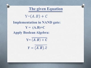
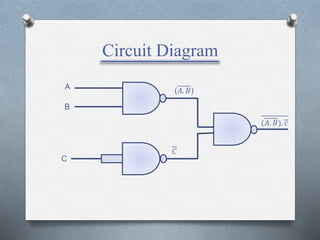
- A circuit diagram and truth table for a circuit with the equation Y=A.B+C.
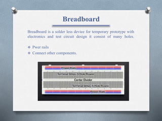
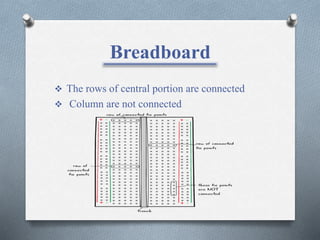
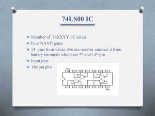
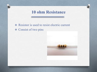
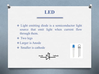
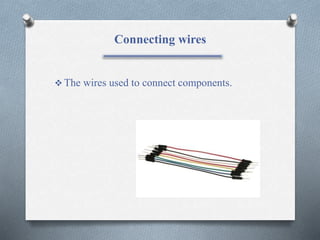
- A description of the components used - a breadboard, 74LS00 IC containing four NAND gates, resistors, LEDs, wires and a 9V battery.
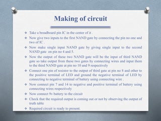
- Steps for constructing the circuit on the breadboard by connecting the IC pins to inputs and outputs and adding an LED and resistor to indicate the output.