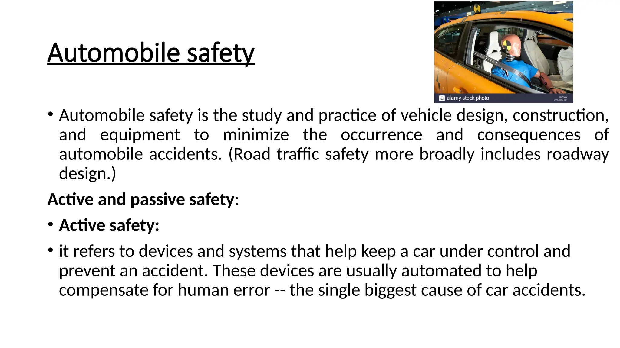
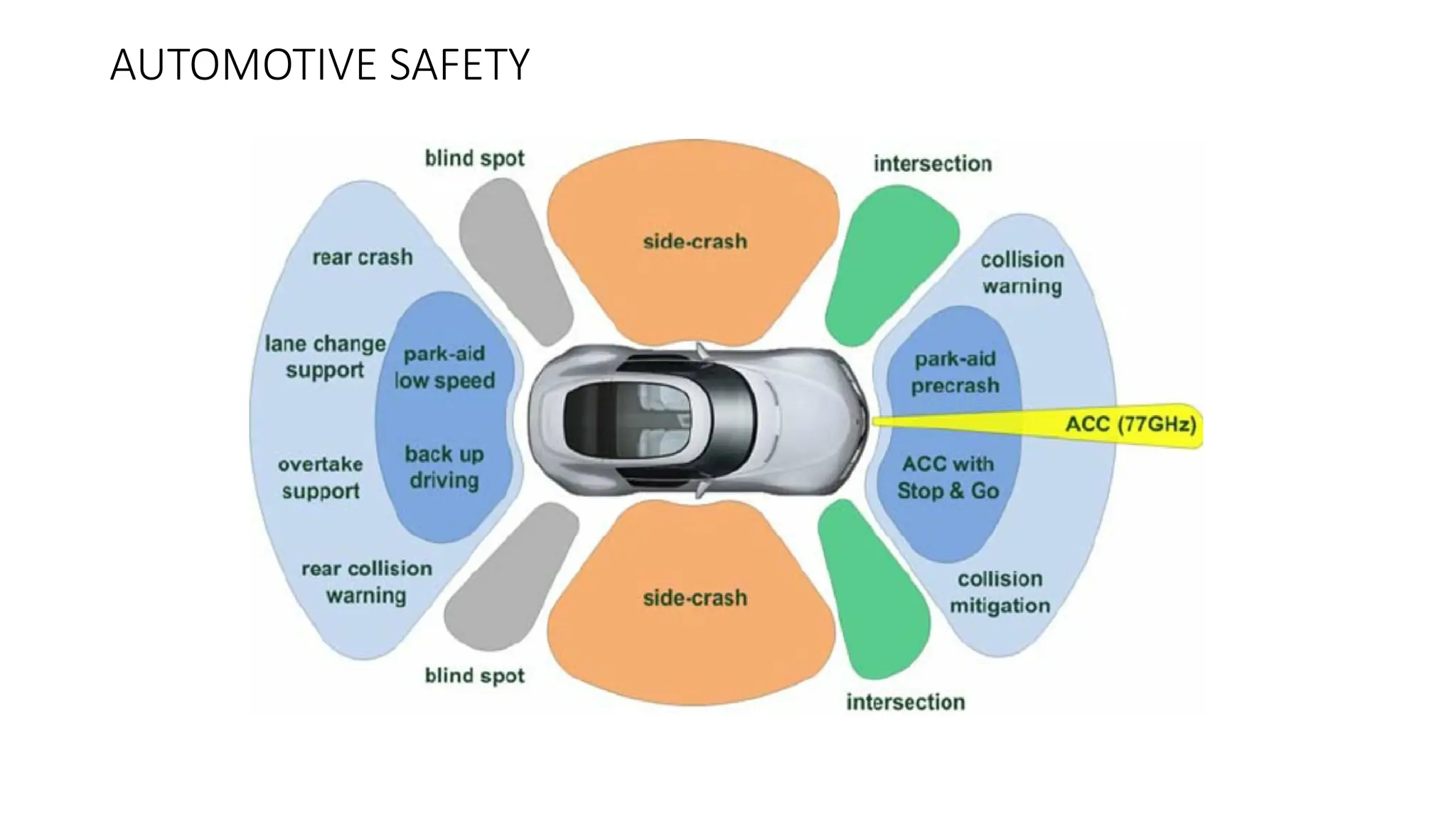
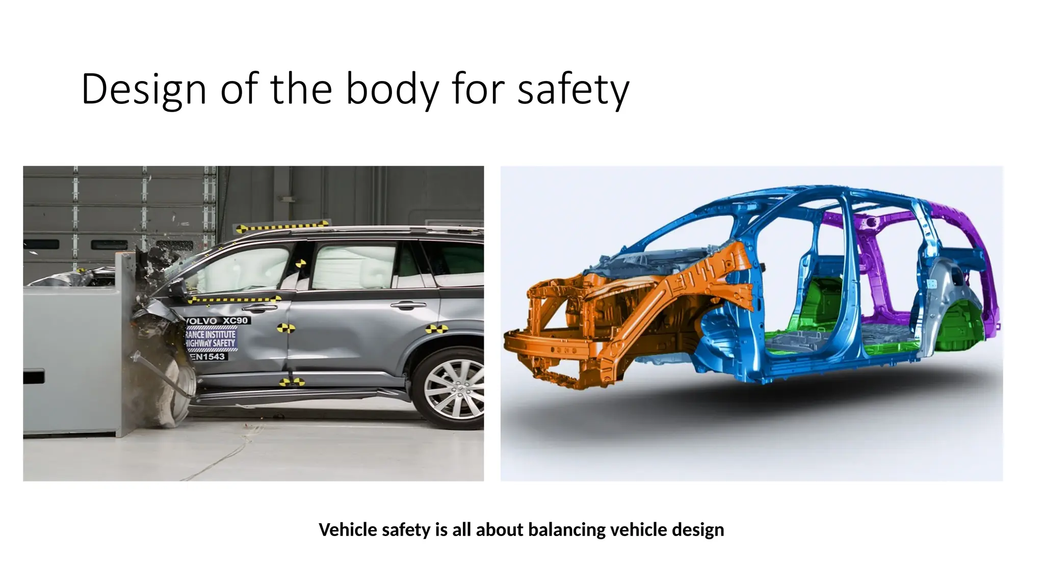
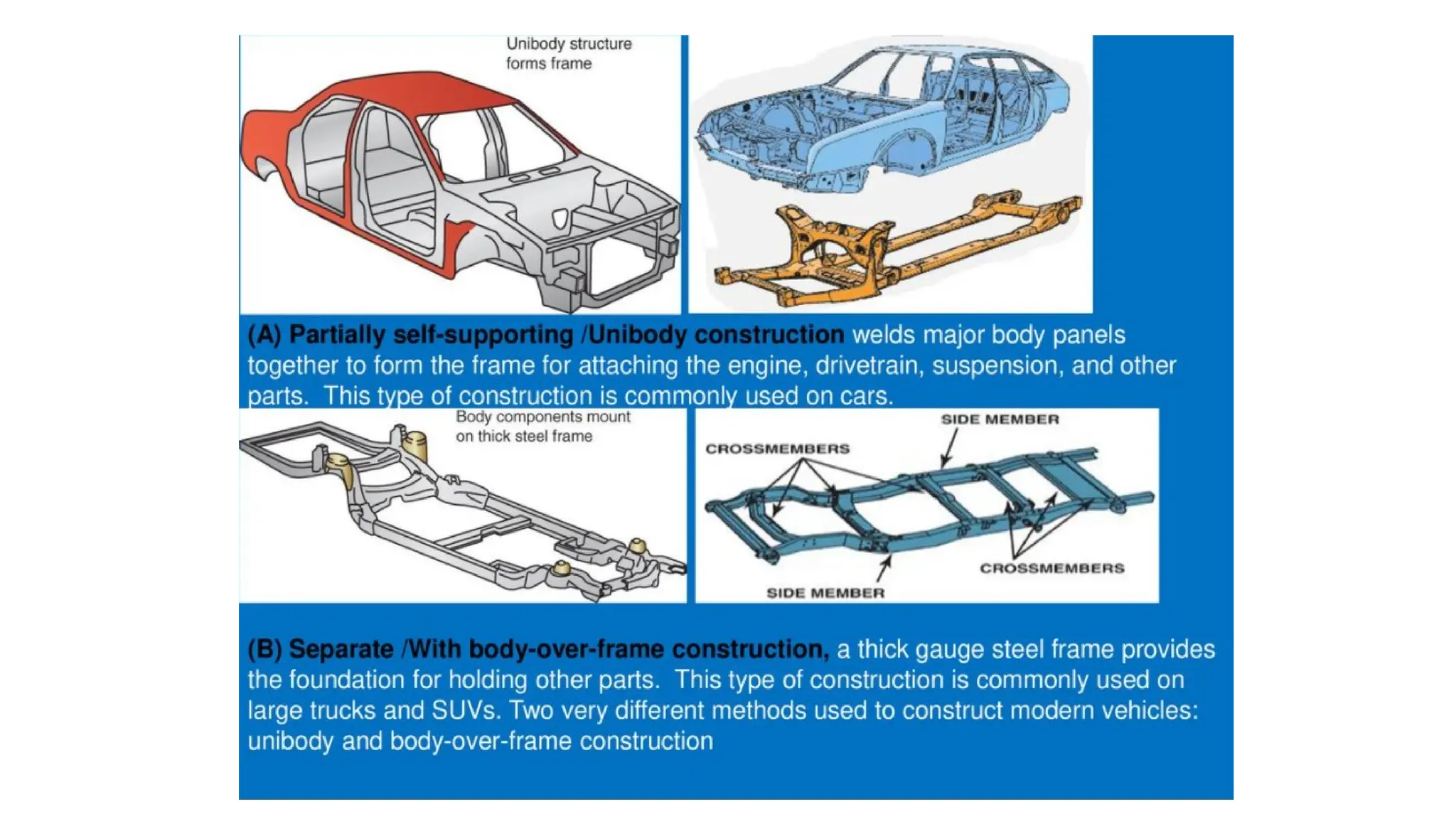
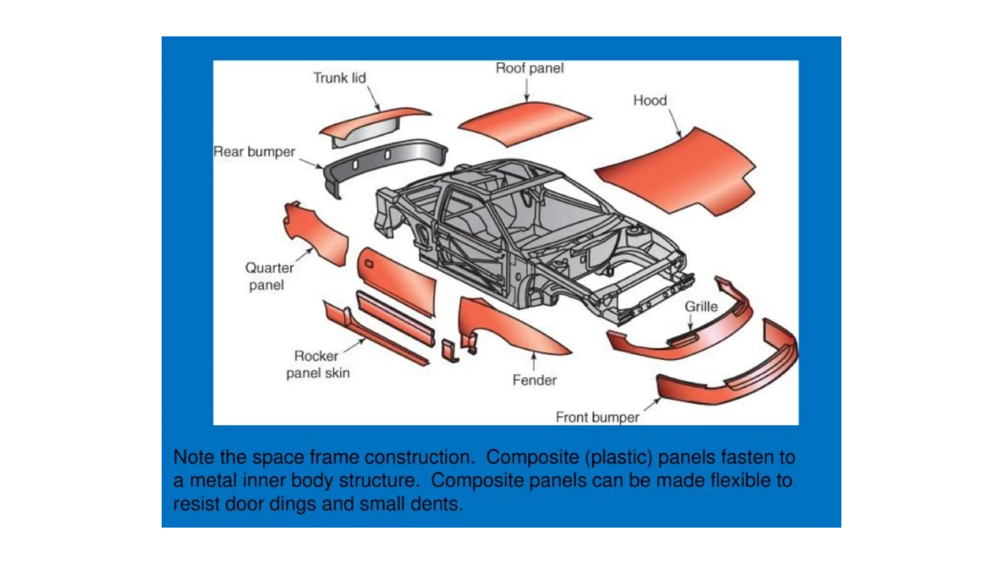
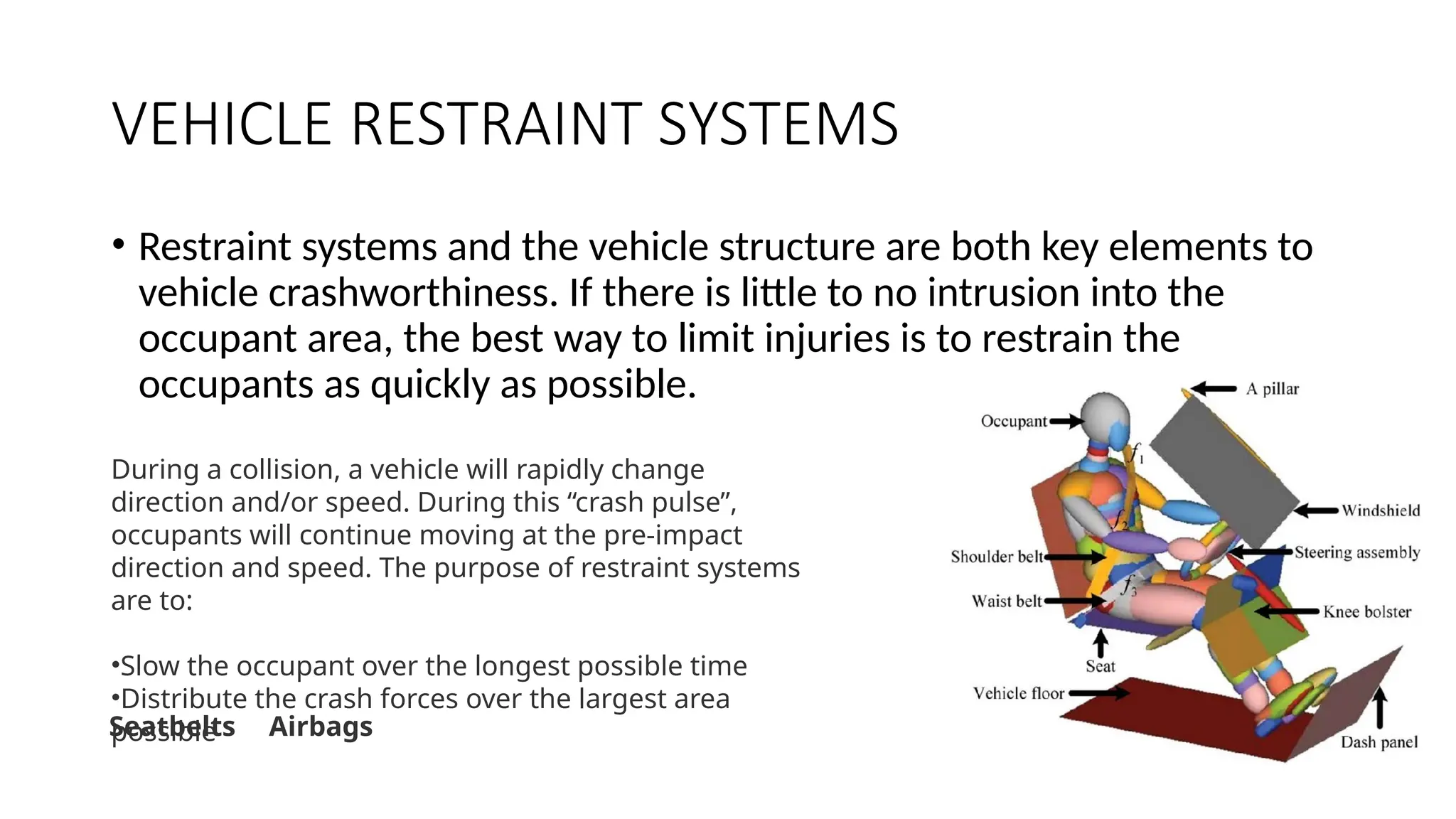
UNIT -1
INTRODUCTION
04/09/2024 1
AUTOMOTIVE SAFTY
Mr. Ramkumar N P
Assistant Professor
Department of Mechanical Engineering
FET-JAIN Deemed to be University
Content
• Design of the body for safety,
• Energy equation, Engine location,
• deceleration of vehicle inside passenger compartment,
• deceleration on impact with stationary and movable obstacle,
• concept of crumble zone,
• safety sandwich construction.
Automobile safety
• Automobile safety is the study and practice of vehicle design, construction,
and equipment to minimize the occurrence and consequences of
automobile accidents. (Road traffic safety more broadly includes roadway
design.)
Active and passive safety:
• Active safety:
• it refers to devices and systems that help keep a car under control and
prevent an accident. These devices are usually automated to help
compensate for human error -- the single biggest cause of car accidents.
example:
• Anti-lock brakes prevent the wheels from locking up when the driver
brakes, enabling the driver to steer while braking.
• Traction control systems prevent the wheels from slipping while the
car is accelerating.
• Electronic stability control keeps the car under control and on the
road.
Passive safety:
• it refers to systems in the car that protect the driver and passengers from injury if an
accident does occur.
Example:
• Air bags provide a cushion to protect the driver and passengers during a crash.
• Seat belts hold passengers in place so that they aren't thrown forward or ejected from the
car.
• Rollover bars protect the car's occupants from injury if the vehicle rolls over during an
accident.
• Head restraints prevent the driver and passengers from getting whiplash during a rear-end
collision.
Crash avoidance:
Crash avoidance systems and devices help the driver and, increasingly,
help the vehicle itself —to avoid a collision. This category includes:
• The vehicle's headlamps, reflectors, and other lights and signals
• The vehicle's mirrors
• The vehicle's brakes, steering, and suspension systems
Driver assistance:
A subset of crash avoidance is driver assistance systems, which help the driver to
detect ordinarily-hidden obstacles and to control the vehicle. Driver assistance
systems include:
i) Automatic Braking systems to prevent or reduce the severity of collision.
ii) Infrared night vision systems to increase seeing distance beyond headlamp range
iii)Adaptive high beam which automatically and continuously adapts the headlamp
range to the distance of vehicles ahead or which are oncoming
iv)Adaptive headlamps swivels headlamps around corners
v) Reverse backup sensors, which alert drivers to difficult-to-see objects in their
path when reversing
vi) Backup camera
• vii) Adaptive cruise control which maintains a safe distance from the vehicle in front
viii) Lane departure warning systems to alert the driver of an unintended departure
from the intended lane of travel
• ix) Tire pressure monitoring systems.
• x)Traction control systems which restore traction if driven wheels begin to spin
• xi) Electronic Stability Control, which intervenes to avert an impending loss of
control
• xii) Anti-lock braking systems
• xiii)Electronic brake-force distribution systems
• xiv)Emergency brake assist systems
• xv) Cornering Brake Control systems
• xvi) Pre-crash system
• xvii) Automated parking system
AUTOMOTIVE SAFETY
Design of the body for safety
Vehicle safety is all about balancing vehicle design
Design of vehicle body for safety
The safety of a vehicle and its passengers can be
improved by properly designing and selecting the material for
vehicle bodies.
The vehicle body structure is subjected to static and
dynamic service loads during the life cycle. It also has to
provide adequate protection in survivable crashes.
At present there are two designs of vehicle body
constructions: 1. Body over frame structure and 2. Uni body
structure.
Body on frame and unibody
• Body on frame is when the body of the car is mounted on a chassis
that carries the powertrain.
• Unibody construction is when the frame and the body of the car are
manufactured as one piece.
Body on Frame Pros:
•Better off-road vehicles
•Higher towing capacity
•Cheaper to build and repair
•Produce less road noise
•Better protected from moisture from the road
Body on Frame Cons:
•Heavier than unibody
•Lower fuel economy rating
•Lack crumple zones
•Rougher rides on normal roads
•More severe accidents
Unibody Pros:
•Easier to design
•Better fuel economy
•More common/easier to find one to buy
•Rollovers less likely
•Smoother ride quality
Unibody Cons:
•Towing capacity not as high
•Off-roading more difficult
•Expensive to repair
•More expensive design and
manufacturing costs
Necessary features of a safe vehicle body:
1. Deformable yet stiff front structure with crumple zones to absorb the
crash kinetic energy from frontal collisions
2. Deformable rear structure to safeguard rear passenger compartment
and protect the fuel tank
3. Properly designed side structures and doors to minimize intrusion in
side impact and prevent doors from opening due to crash loads
4. Strong roof structure for rollover protection
5. Properly designed restraint systems with working in harmony with
the vehicle structure
6. Accommodate various chassis designs for different power train
locations and drive train configurations.
VEHICLE RESTRAINT SYSTEMS
• Restraint systems and the vehicle structure are both key elements to
vehicle crashworthiness. If there is little to no intrusion into the
occupant area, the best way to limit injuries is to restrain the
occupants as quickly as possible.
During a collision, a vehicle will rapidly change
direction and/or speed. During this “crash pulse”,
occupants will continue moving at the pre-impact
direction and speed. The purpose of restraint systems
are to:
•Slow the occupant over the longest possible time
•Distribute the crash forces over the largest area
possible
Seatbelts Airbags
Design techniques/strategies:
1. Desired dummy performance:
 Dummy is a physical model representing humans inside a car.
 To model a car for safety, it should be modeled for proper crash energy
management.
 As the human beings are to be safeguarded, the interaction of the human beings
with the restraint system during a crash has to be studied first. This branch of
study is widely known as bio-mechanics.
The following design techniques/strategies are to be followed while designing a car body (especially
front structure) to reduce the impact of crash and increase the safety of the car and passengers.
2. Stiff cage structural concept:
Stiff cage is the passenger compartment structure which provides
protection for the passengers in all modes of survivable collisions.
The necessary features of a good stiff cage structure are:
1. sufficient peak load capacity to support the energy absorbing
members in front of it,
2. High crash energy absorption. The stiff cage structure should
withstand all the extreme loads and the severe deformation.
Energy equation
• The application of the conservation of energy principle provides a powerful tool for
problem solving.
• For example, the solution for the impact velocity of a falling object is much easier by
energy methods.
• The basic reason for the advantage of the energy approach is that just the beginning
and ending energies need be considered; intermediate processes do not need to be
examined in detail since conservation of energy guarantees that the final energy of
the system is the same as the initial energy.
• The work- energy principle is also a useful approach to the use of conservation of
energy in mechanics problem solving.
• It is particularly useful in cases where an object is brought to rest as in a car crash or
the normal stopping of an automobile.
• Kinetic energy is energy of motion.
• Objects that are moving, have kinetic energy (KE). If a car crashes into a wall at 5
mph, it shouldn't do much damage to the car. But if it hits the wall at 40 mph, the
car will most likely be totaled.
• Kinetic energy is similar to potential energy.
• The more the object weighs, and the faster it is moving, the more kinetic energy it
has.
• The formula for KE is: KE = 1/2*m*v2
where m is the mass and v is the velocity.
• One of the interesting things about kinetic energy is that it increases
with the velocity squared.
• This means that if a car is going twice as fast, it has four times the
energy. You may have noticed that your car accelerates much faster
from 0 mph to 20 mph than it does from 40 mph to 60 mph.
There are a lot of other factors involved in determining a car's acceleration, such
as aerodynamic drag, which also increases with the velocity squared.
Engine location
• Front engine:
The large mass of an engine at the front of the car gives the driver
protection in the event of a head on collision. Engine cooling is simpler to
arrange and in addition the cornering ability of a vehicle is normally better
if the weight is concentrated at the front.
• Rear engine:
It increases the load on the rear driving wheels, giving them better grip of the
road. Most rear- engine layouts have been confined to comparatively small cars,
because the heavy engine at the rear has an adverse effect on the ‘handling’ of the
car by making it ‘tail-heavy’.
Also it takes up good deal of space that would be used on a front-engine car for
carrying luggage.
Most of the space vacated by the engine at the front end can be used for luggage,
but this space is usually less than that available at the rear.
• Central and mid-engine:
These engine situations generally apply to sports cars
because the engine sitting gives a load distribution that
achieves both good handling and maximum traction
from the driving wheels.
These advantages, whilst of great importance for special
cars, are outweighed in the case of everyday cars by the
fact that the engine takes up space that would normally
be occupied by passengers.
The mid-engine layout shown combines the engine and
transmission components in one unit. The term mid-
engine is used because the engine is mounted in front of
rear axle line.
Deceleration of vehicle and passenger compartment on impact
with stationary and movable obstacle.
It is important to study the deceleration inside passenger compartment to know the effect of crash
completely, so that the crash avoidance systems can be suitably designed.
For example, if the deceleration of the passenger after crash is very high, the air bag system and the seat belt
system has to be so designed that the activation time for them is reduced to a lower value
Otherwise it may lead to injuries and fatalities.
Usually tests are conducted to know the deceleration behavior after the crash with a stationary obstacle.
The tests are conducted at the following speeds:
• 15 mph (miles per hour)
• 20 mph
• 40 mph
• 50 mph
• 15 mph test:
The following pictures show the body deformation and acceleration graph after
crash.
The body deformation is less as the vehicle speed is low. The crash occurs at time 0
seconds. From the graph, we can know that after the crash, deceleration occurs
which is shown in the negative (lower) portion. After some time the acceleration
slowly comes to zero (the car stops)
• 20 mph test:
In the 20 mph test, the body deformation is more than 15 mph test. Moreover, the
acceleration has reduced to a further lower value (up to 35 g) in the negative direction.
In this case the maximum deceleration is obtained in 50 milli seconds whereas for 10 mph
test it was 35 milli seconds. The rebound velocity for this case is1.7 mph whereas for 10
mph it is 1.3 mph.40 mph test: In the 40 mph test, we can see that the acceleration curve
goes down (deceleration) then suddenly goes up in the positive region (acceleration).
This is due to the fact that, at 40 mph, the deformation is more and the accelerometer
(sensor) mounting area has buckled and resulted in an increase in acceleration value. The
body deformation is also high such that the accelerometer mounting area is also damaged.
So, we have to carefully analyze the graph to study the situation. The graphs are shown
below:
• 40 mph test:
In the 40 mph test, we can see that the acceleration curve goes down (deceleration)
then suddenly goes up in the positive region (acceleration).
This is due to the fact that, at 40 mph, the deformation is more and the
accelerometer (sensor) mounting area has buckled and resulted in an increase in
acceleration value.
The body deformation is also high such that the accelerometer mounting area is
also damaged. So, we have to carefully analyze the graph to study the situation.
• 50 mph test:
The body deformation is very high as the speed is more. The
acceleration curve shows that the maximum deceleration is around 35g
and happens in time duration of 45 milli seconds. The rebound velocity
is 1.6 mph.
Deceleration on impact with a movable obstacle:
• A movable obstacle can be
another car or any other vehicle.
Let us consider a car is impacting
with another car.
• We shall study for the two cars;
one car which is impacting the
second car, the other car is which
is being impacted. In this case the
test is conducted at 40 mph.
Impacting vehicle:
• Impacted vehicle
Crumple zone
• The crumple zone of an automobile is a structural feature designed to compress
during an accident to absorb energy from the impact.
• Typically, crumple zones are located in the front part of the vehicle, in order to
absorb the impact of a head-on collision, though they may be found on other parts of
the vehicle as well. Some racing cars use aluminum or composite honeycomb to form
an 'impact attenuator' for this purpose.
In a crash, crumple
zones help transfer some of
the car's kinetic energy into
controlled deformation, or
crumpling, at impact. This
may create more vehicle
damage, but the severity of
personal injury likely will be
reduced.
Also known as a crush zone, a crumple zone is an area of
a vehicle (usually located in the front and rear)
that's designed to crumple or crush when hit with
significant force.
• It was an inventor Bela Barenyi who pioneered the idea that passengers were safer in
a vehicle that was designed to easily absorb the energy from an impact and keep that
energy away from the people inside the cabin.
• Barenyi devised a system of placing the car's components in a certain configuration
that kept the kinetic energy in the event of a crash away from a bubble protecting the
car's occupants.
• Mercedes obtained patent from Barenyi's invention way back in 1952 and the
technology was first introduced into production cars in 1959 in the Mercedes-Benz
220, 220 S and 220 SE models.
Function:
• Crumple zones work by managing crash energy, absorbing it within the outer
sections of the vehicle, rather than being directly transmitted to the occupants,
while also preventing intrusion into or deformation of the passenger cabin. This
better protects car occupants against injury.
• Volvo introduced the side crumple zone; with the introduction of the SIPS (Side
Impact Protection System) in the early 1990s.
• The purpose of crumple zones is to slow down the collision and to absorb energy.
It is like the difference between slamming someone into a wall headfirst
(fracturing their skull) and shoulder-first (bruising their flesh slightly) is that the
arm, being softer, has tens of times longer to slow its speed, yielding a little at a
time, than the hard skull, which isn't in contact with the wall until it has to deal
with extremely high pressures.
• Seatbelts restrain the passenger so they don't fly through the windshield, and are
in the correct position for the airbag and also spread the loading of impact on the
body.
• Seat belts also absorb energy by being designed to stretch during an impact, so
that there is less speed differential between the passenger's body and their
vehicle interior.
• In short: A passenger whose body is decelerated more slowly due to the crumple
zone (and other devices) over a longer time, survives much more often than a
passenger whose body indirectly impacts a hard, undamaged metal car body
which has come to a halt nearly instantaneously.
• The final impact after a passenger's body hits the car interior, airbag or seat belts,
is that of the internal organs hitting the ribcage or skull.
• The force of this impact is the mechanism through which car crashes cause
disabling or life threatening injury.
• The sequence of energy is dissipating and speed reducing technologies - crumple
zone - seat belt - airbags - padded interior, are designed to work together as
system, to reduce the force of this final impact.
• A common misconception about crumple zones is that they reduce safety by
allowing the vehicle's body to collapse, crushing the occupants.
• Modern vehicles using what are commonly termed 'crumple zones' provide far
superior protection for their occupants in severe tests than older models, or SUVs
that use a separate chassis frame and have no crumple zones.
Safety sandwich construction
Sandwich panel constructions using metallic
and polymeric honeycombs and foams have
been used for many years in the competition
and high performance sectors of the
automotive industry, and there is considerable
knowledge and confidence in their static,
dynamic and crashworthiness properties.
However, it should be noted that with regard
to vehicle structures, sandwich panels have
only been used to produce extremely limited
numbers of product and have been essentially
hand-worked.
• The potential advantages of polymer composites for automotive parts (high specific
strength and stiffness, corrosion resistance) are well known. Further benefits are
available from the use of sandwich construction, in which a relatively stiff, strong skin is
bonded either side of a much thicker, lightweight core.
• Sandwich panels have been widely used for structural applications in the marine,
aerospace and performance automotive industries for several decades.
• Lightweight core materials have included polymer foams and metallic, paper or polymer
honeycombs.
• These have been used in various combinations with skins of carbon, glass and/or
aramid fiber-reinforced polymer, as well as aluminium.
• The principle of sandwich construction is that bending loads are carried by the skins,
while the core transmits shear load.
• They enable large gains in structural efficiency, since the thickness (and hence flexural
rigidity) of panels can be increased without significant weight penalty. Some
representative properties of sandwich panels are given in Table
• In high performance car construction, most sandwich panel elements are vacuum bag/autoclave
molded on a contact tool, usually in several stages (e.g. first skin; core to skin bond; second skin).
• Although this permits complex shapes to be produced on low cost tooling, it is necessarily a time
consuming and labor intensive process.
• A high degree of cleanliness and sophisticated process control are required, and inspection is
notoriously difficult.
• However, sandwich panels are also available as flat sheet, stock material.
• Hexcel Composites, for example, supply arrange of honeycomb cored sheets of varying specifications
which is widely used for building cladding, aircraft flooring, luggage bins and bulkheads.
• The use of a stock material is attractive, since primary material quality and specification becomes the
responsibility of the supplier, not the manufacturer. Several techniques are well established for the
shaping and assembly of structural components from flat sandwich panel.
• Panels may be bent to required angles by removing a defined strip of material from the inner skin,
then folding and adhesively bonding the joint.
Assignment
Importance of ergonomics in automotive safety?
Thank you

1 Unit 1.pptx INTRODUCTION TO AUTOMOBILE SAFETY

  • 1.
    UNIT -1 INTRODUCTION 04/09/2024 1 AUTOMOTIVESAFTY Mr. Ramkumar N P Assistant Professor Department of Mechanical Engineering FET-JAIN Deemed to be University
  • 2.
    Content • Design ofthe body for safety, • Energy equation, Engine location, • deceleration of vehicle inside passenger compartment, • deceleration on impact with stationary and movable obstacle, • concept of crumble zone, • safety sandwich construction.
  • 3.
    Automobile safety • Automobilesafety is the study and practice of vehicle design, construction, and equipment to minimize the occurrence and consequences of automobile accidents. (Road traffic safety more broadly includes roadway design.) Active and passive safety: • Active safety: • it refers to devices and systems that help keep a car under control and prevent an accident. These devices are usually automated to help compensate for human error -- the single biggest cause of car accidents.
  • 4.
    example: • Anti-lock brakesprevent the wheels from locking up when the driver brakes, enabling the driver to steer while braking. • Traction control systems prevent the wheels from slipping while the car is accelerating. • Electronic stability control keeps the car under control and on the road.
  • 5.
    Passive safety: • itrefers to systems in the car that protect the driver and passengers from injury if an accident does occur. Example: • Air bags provide a cushion to protect the driver and passengers during a crash. • Seat belts hold passengers in place so that they aren't thrown forward or ejected from the car. • Rollover bars protect the car's occupants from injury if the vehicle rolls over during an accident. • Head restraints prevent the driver and passengers from getting whiplash during a rear-end collision.
  • 6.
    Crash avoidance: Crash avoidancesystems and devices help the driver and, increasingly, help the vehicle itself —to avoid a collision. This category includes: • The vehicle's headlamps, reflectors, and other lights and signals • The vehicle's mirrors • The vehicle's brakes, steering, and suspension systems
  • 7.
    Driver assistance: A subsetof crash avoidance is driver assistance systems, which help the driver to detect ordinarily-hidden obstacles and to control the vehicle. Driver assistance systems include: i) Automatic Braking systems to prevent or reduce the severity of collision. ii) Infrared night vision systems to increase seeing distance beyond headlamp range iii)Adaptive high beam which automatically and continuously adapts the headlamp range to the distance of vehicles ahead or which are oncoming iv)Adaptive headlamps swivels headlamps around corners v) Reverse backup sensors, which alert drivers to difficult-to-see objects in their path when reversing vi) Backup camera
  • 8.
    • vii) Adaptivecruise control which maintains a safe distance from the vehicle in front viii) Lane departure warning systems to alert the driver of an unintended departure from the intended lane of travel • ix) Tire pressure monitoring systems. • x)Traction control systems which restore traction if driven wheels begin to spin • xi) Electronic Stability Control, which intervenes to avert an impending loss of control • xii) Anti-lock braking systems • xiii)Electronic brake-force distribution systems
  • 9.
    • xiv)Emergency brakeassist systems • xv) Cornering Brake Control systems • xvi) Pre-crash system • xvii) Automated parking system
  • 10.
  • 11.
    Design of thebody for safety Vehicle safety is all about balancing vehicle design
  • 12.
    Design of vehiclebody for safety The safety of a vehicle and its passengers can be improved by properly designing and selecting the material for vehicle bodies. The vehicle body structure is subjected to static and dynamic service loads during the life cycle. It also has to provide adequate protection in survivable crashes. At present there are two designs of vehicle body constructions: 1. Body over frame structure and 2. Uni body structure.
  • 13.
    Body on frameand unibody • Body on frame is when the body of the car is mounted on a chassis that carries the powertrain. • Unibody construction is when the frame and the body of the car are manufactured as one piece. Body on Frame Pros: •Better off-road vehicles •Higher towing capacity •Cheaper to build and repair •Produce less road noise •Better protected from moisture from the road Body on Frame Cons: •Heavier than unibody •Lower fuel economy rating •Lack crumple zones •Rougher rides on normal roads •More severe accidents
  • 14.
    Unibody Pros: •Easier todesign •Better fuel economy •More common/easier to find one to buy •Rollovers less likely •Smoother ride quality Unibody Cons: •Towing capacity not as high •Off-roading more difficult •Expensive to repair •More expensive design and manufacturing costs
  • 25.
    Necessary features ofa safe vehicle body: 1. Deformable yet stiff front structure with crumple zones to absorb the crash kinetic energy from frontal collisions 2. Deformable rear structure to safeguard rear passenger compartment and protect the fuel tank 3. Properly designed side structures and doors to minimize intrusion in side impact and prevent doors from opening due to crash loads 4. Strong roof structure for rollover protection 5. Properly designed restraint systems with working in harmony with the vehicle structure 6. Accommodate various chassis designs for different power train locations and drive train configurations.
  • 26.
    VEHICLE RESTRAINT SYSTEMS •Restraint systems and the vehicle structure are both key elements to vehicle crashworthiness. If there is little to no intrusion into the occupant area, the best way to limit injuries is to restrain the occupants as quickly as possible. During a collision, a vehicle will rapidly change direction and/or speed. During this “crash pulse”, occupants will continue moving at the pre-impact direction and speed. The purpose of restraint systems are to: •Slow the occupant over the longest possible time •Distribute the crash forces over the largest area possible Seatbelts Airbags
  • 27.
    Design techniques/strategies: 1. Desireddummy performance:  Dummy is a physical model representing humans inside a car.  To model a car for safety, it should be modeled for proper crash energy management.  As the human beings are to be safeguarded, the interaction of the human beings with the restraint system during a crash has to be studied first. This branch of study is widely known as bio-mechanics. The following design techniques/strategies are to be followed while designing a car body (especially front structure) to reduce the impact of crash and increase the safety of the car and passengers.
  • 28.
    2. Stiff cagestructural concept: Stiff cage is the passenger compartment structure which provides protection for the passengers in all modes of survivable collisions. The necessary features of a good stiff cage structure are: 1. sufficient peak load capacity to support the energy absorbing members in front of it, 2. High crash energy absorption. The stiff cage structure should withstand all the extreme loads and the severe deformation.
  • 29.
    Energy equation • Theapplication of the conservation of energy principle provides a powerful tool for problem solving. • For example, the solution for the impact velocity of a falling object is much easier by energy methods. • The basic reason for the advantage of the energy approach is that just the beginning and ending energies need be considered; intermediate processes do not need to be examined in detail since conservation of energy guarantees that the final energy of the system is the same as the initial energy. • The work- energy principle is also a useful approach to the use of conservation of energy in mechanics problem solving. • It is particularly useful in cases where an object is brought to rest as in a car crash or the normal stopping of an automobile.
  • 30.
    • Kinetic energyis energy of motion. • Objects that are moving, have kinetic energy (KE). If a car crashes into a wall at 5 mph, it shouldn't do much damage to the car. But if it hits the wall at 40 mph, the car will most likely be totaled. • Kinetic energy is similar to potential energy. • The more the object weighs, and the faster it is moving, the more kinetic energy it has. • The formula for KE is: KE = 1/2*m*v2 where m is the mass and v is the velocity.
  • 31.
    • One ofthe interesting things about kinetic energy is that it increases with the velocity squared. • This means that if a car is going twice as fast, it has four times the energy. You may have noticed that your car accelerates much faster from 0 mph to 20 mph than it does from 40 mph to 60 mph. There are a lot of other factors involved in determining a car's acceleration, such as aerodynamic drag, which also increases with the velocity squared.
  • 32.
    Engine location • Frontengine: The large mass of an engine at the front of the car gives the driver protection in the event of a head on collision. Engine cooling is simpler to arrange and in addition the cornering ability of a vehicle is normally better if the weight is concentrated at the front.
  • 33.
    • Rear engine: Itincreases the load on the rear driving wheels, giving them better grip of the road. Most rear- engine layouts have been confined to comparatively small cars, because the heavy engine at the rear has an adverse effect on the ‘handling’ of the car by making it ‘tail-heavy’. Also it takes up good deal of space that would be used on a front-engine car for carrying luggage. Most of the space vacated by the engine at the front end can be used for luggage, but this space is usually less than that available at the rear.
  • 34.
    • Central andmid-engine: These engine situations generally apply to sports cars because the engine sitting gives a load distribution that achieves both good handling and maximum traction from the driving wheels. These advantages, whilst of great importance for special cars, are outweighed in the case of everyday cars by the fact that the engine takes up space that would normally be occupied by passengers. The mid-engine layout shown combines the engine and transmission components in one unit. The term mid- engine is used because the engine is mounted in front of rear axle line.
  • 35.
    Deceleration of vehicleand passenger compartment on impact with stationary and movable obstacle. It is important to study the deceleration inside passenger compartment to know the effect of crash completely, so that the crash avoidance systems can be suitably designed. For example, if the deceleration of the passenger after crash is very high, the air bag system and the seat belt system has to be so designed that the activation time for them is reduced to a lower value Otherwise it may lead to injuries and fatalities. Usually tests are conducted to know the deceleration behavior after the crash with a stationary obstacle. The tests are conducted at the following speeds: • 15 mph (miles per hour) • 20 mph • 40 mph • 50 mph
  • 36.
    • 15 mphtest: The following pictures show the body deformation and acceleration graph after crash. The body deformation is less as the vehicle speed is low. The crash occurs at time 0 seconds. From the graph, we can know that after the crash, deceleration occurs which is shown in the negative (lower) portion. After some time the acceleration slowly comes to zero (the car stops)
  • 37.
    • 20 mphtest: In the 20 mph test, the body deformation is more than 15 mph test. Moreover, the acceleration has reduced to a further lower value (up to 35 g) in the negative direction. In this case the maximum deceleration is obtained in 50 milli seconds whereas for 10 mph test it was 35 milli seconds. The rebound velocity for this case is1.7 mph whereas for 10 mph it is 1.3 mph.40 mph test: In the 40 mph test, we can see that the acceleration curve goes down (deceleration) then suddenly goes up in the positive region (acceleration). This is due to the fact that, at 40 mph, the deformation is more and the accelerometer (sensor) mounting area has buckled and resulted in an increase in acceleration value. The body deformation is also high such that the accelerometer mounting area is also damaged. So, we have to carefully analyze the graph to study the situation. The graphs are shown below:
  • 38.
    • 40 mphtest: In the 40 mph test, we can see that the acceleration curve goes down (deceleration) then suddenly goes up in the positive region (acceleration). This is due to the fact that, at 40 mph, the deformation is more and the accelerometer (sensor) mounting area has buckled and resulted in an increase in acceleration value. The body deformation is also high such that the accelerometer mounting area is also damaged. So, we have to carefully analyze the graph to study the situation.
  • 39.
    • 50 mphtest: The body deformation is very high as the speed is more. The acceleration curve shows that the maximum deceleration is around 35g and happens in time duration of 45 milli seconds. The rebound velocity is 1.6 mph.
  • 40.
    Deceleration on impactwith a movable obstacle: • A movable obstacle can be another car or any other vehicle. Let us consider a car is impacting with another car. • We shall study for the two cars; one car which is impacting the second car, the other car is which is being impacted. In this case the test is conducted at 40 mph. Impacting vehicle:
  • 41.
  • 42.
    Crumple zone • Thecrumple zone of an automobile is a structural feature designed to compress during an accident to absorb energy from the impact. • Typically, crumple zones are located in the front part of the vehicle, in order to absorb the impact of a head-on collision, though they may be found on other parts of the vehicle as well. Some racing cars use aluminum or composite honeycomb to form an 'impact attenuator' for this purpose. In a crash, crumple zones help transfer some of the car's kinetic energy into controlled deformation, or crumpling, at impact. This may create more vehicle damage, but the severity of personal injury likely will be reduced. Also known as a crush zone, a crumple zone is an area of a vehicle (usually located in the front and rear) that's designed to crumple or crush when hit with significant force.
  • 43.
    • It wasan inventor Bela Barenyi who pioneered the idea that passengers were safer in a vehicle that was designed to easily absorb the energy from an impact and keep that energy away from the people inside the cabin. • Barenyi devised a system of placing the car's components in a certain configuration that kept the kinetic energy in the event of a crash away from a bubble protecting the car's occupants. • Mercedes obtained patent from Barenyi's invention way back in 1952 and the technology was first introduced into production cars in 1959 in the Mercedes-Benz 220, 220 S and 220 SE models.
  • 44.
    Function: • Crumple zoneswork by managing crash energy, absorbing it within the outer sections of the vehicle, rather than being directly transmitted to the occupants, while also preventing intrusion into or deformation of the passenger cabin. This better protects car occupants against injury. • Volvo introduced the side crumple zone; with the introduction of the SIPS (Side Impact Protection System) in the early 1990s. • The purpose of crumple zones is to slow down the collision and to absorb energy. It is like the difference between slamming someone into a wall headfirst (fracturing their skull) and shoulder-first (bruising their flesh slightly) is that the arm, being softer, has tens of times longer to slow its speed, yielding a little at a time, than the hard skull, which isn't in contact with the wall until it has to deal with extremely high pressures.
  • 45.
    • Seatbelts restrainthe passenger so they don't fly through the windshield, and are in the correct position for the airbag and also spread the loading of impact on the body. • Seat belts also absorb energy by being designed to stretch during an impact, so that there is less speed differential between the passenger's body and their vehicle interior. • In short: A passenger whose body is decelerated more slowly due to the crumple zone (and other devices) over a longer time, survives much more often than a passenger whose body indirectly impacts a hard, undamaged metal car body which has come to a halt nearly instantaneously. • The final impact after a passenger's body hits the car interior, airbag or seat belts, is that of the internal organs hitting the ribcage or skull. • The force of this impact is the mechanism through which car crashes cause disabling or life threatening injury.
  • 46.
    • The sequenceof energy is dissipating and speed reducing technologies - crumple zone - seat belt - airbags - padded interior, are designed to work together as system, to reduce the force of this final impact. • A common misconception about crumple zones is that they reduce safety by allowing the vehicle's body to collapse, crushing the occupants. • Modern vehicles using what are commonly termed 'crumple zones' provide far superior protection for their occupants in severe tests than older models, or SUVs that use a separate chassis frame and have no crumple zones.
  • 47.
    Safety sandwich construction Sandwichpanel constructions using metallic and polymeric honeycombs and foams have been used for many years in the competition and high performance sectors of the automotive industry, and there is considerable knowledge and confidence in their static, dynamic and crashworthiness properties. However, it should be noted that with regard to vehicle structures, sandwich panels have only been used to produce extremely limited numbers of product and have been essentially hand-worked.
  • 48.
    • The potentialadvantages of polymer composites for automotive parts (high specific strength and stiffness, corrosion resistance) are well known. Further benefits are available from the use of sandwich construction, in which a relatively stiff, strong skin is bonded either side of a much thicker, lightweight core. • Sandwich panels have been widely used for structural applications in the marine, aerospace and performance automotive industries for several decades. • Lightweight core materials have included polymer foams and metallic, paper or polymer honeycombs. • These have been used in various combinations with skins of carbon, glass and/or aramid fiber-reinforced polymer, as well as aluminium. • The principle of sandwich construction is that bending loads are carried by the skins, while the core transmits shear load. • They enable large gains in structural efficiency, since the thickness (and hence flexural rigidity) of panels can be increased without significant weight penalty. Some representative properties of sandwich panels are given in Table
  • 50.
    • In highperformance car construction, most sandwich panel elements are vacuum bag/autoclave molded on a contact tool, usually in several stages (e.g. first skin; core to skin bond; second skin). • Although this permits complex shapes to be produced on low cost tooling, it is necessarily a time consuming and labor intensive process. • A high degree of cleanliness and sophisticated process control are required, and inspection is notoriously difficult. • However, sandwich panels are also available as flat sheet, stock material. • Hexcel Composites, for example, supply arrange of honeycomb cored sheets of varying specifications which is widely used for building cladding, aircraft flooring, luggage bins and bulkheads. • The use of a stock material is attractive, since primary material quality and specification becomes the responsibility of the supplier, not the manufacturer. Several techniques are well established for the shaping and assembly of structural components from flat sandwich panel. • Panels may be bent to required angles by removing a defined strip of material from the inner skin, then folding and adhesively bonding the joint.
  • 51.
  • 52.