Download to read offline
![International Journal of Engineering and Technical Research (IJETR)
ISSN: 2321-0869 (O) 2454-4698 (P), Volume-5, Issue-3, July 2016
86 www.erpublication.org
Abstract— Higher Order Statistics are used in digital signal
processing as a powerful analytical tool for the analysis of
signals and systems. These statistics are very useful in problems
where either non-Gaussianity or non-minimum phase. The
computation of the fourth-order cross moments from incoming
time-series data is an intensive process and requires parallel
processing techniques and fast computing systems in order to
follow the requirements of real-time processing. This paper
presents an FPGA based design for high-speed computation of
fourth-order cross moments. The proposed design is coded in
VHDL and functionally verified by implementing it on Xilinx
Virtex-5 FPGA. Simulations results are presented. The
proposed design operates at a maximum frequency of 375 MHz.
Index Terms— HOS, Cumulant 4, Correlation, parallel
design, high speed computation, FPGA
I. INTRODUCTION
In the digital signal processing field, higher order statistics
(HOS), especially the third and fourth order cumulants are
commonly used. They have a wide applicability in many
fields such as sonar, radar, seismic data processing, adaptive
filtering, blind equalization, array processing, data
communication, time-delay estimation, speech and image
processing, texture analysis, pattern recognition, motion
estimation and biomedical signal processing [Nikais
93][Manolakos 91]. In this paper, the exploitation of these
orders for communication systems is presented.
In practice, Cumulants until order four are mostly used.
However, for higher performance, the exploitation of a
high-level hardware description language is the best solution.
It is possible to use VHSIC Hardware Description Language
(VHDL), Application Specific Integrated Circuit (ASIC) or
Field Programmable Gate Array (FPGA).
FPGA is a revolutionary device that combines a flexibility of
both hardware and software. FPGAs are very useful for
operations that process large data streams, such as digital
signal processing and networking. In comparison with the
microprocessor-based designs, FPGA can be faster hundreds
of times than microprocessor-based designs because it
implements parallel spatial computations and simultaneously
computing millions of operations in resources distributed
across a silicon chip. The other benefit of FPGA is can be
programmed and reprogrammed several times. In this paper,
we present FPGA based design for the high speed
Lamyae Maatougui, IEMN-DOAE laboratory, UVHC Valenciennes,
France
Laila Sakkila, IEMN-DOAE laboratory, UVHC Valenciennes, France
Rahmad Sadli, IEMN-DOAE laboratory, UVHC Valenciennes, France
Atika Rivenq, IEMN-DOAE laboratory, UVHC Valenciennes, France
computation of fourth-order cross moments. Two designs are
proposed; the first bases on an already completed correlation
design, the second based on matrix multiplication algorithm
[Alshebeili 01]. A comparison between the proposed design
has been performed and the more efficient of them was been
implemented. For both of designs, the computation of
fourth-order crosses moments exploits intrinsic parallelism at
technology FPGA.
The remainder of the paper is organized as follows. A brief
introduction to HOS and the simulation result in Matlab for
the cumulant 4 are discussed in section 2.Two designs for the
computation of fourth-order cross moments are described in
section 3 and the architectural details for them have been
discussed. FPGA implementation results for correlation are
summarized in section 4. Finally, conclusion and prospects
are given in section 5.
II. HIGHER ORDER STATISTICS
HOS is a technique for interpreting and analyzing the
characteristics of a random process. HOS consists of
higher-order moment spectra, which are defined for
deterministic signals and Cumulant spectra, which are defined
for random process.
Contrary to second-order statistic, the HOS are well used due
to their ability to maintain phase information and their
robustness to additive Gaussian noise. HOS are
multidimensional functions, then; the calculation complexity
of HOS far exceeds that of conventional second-order
statistics [Sakkila 09].
The characteristics of HOS are: suppression of Gaussian
noise, reconstruction of the phase as well as magnitude
response of signals and detection of the nonlinearities in the
data [Sakkila 09].
An approach based on matrix multiplication for the
computation of higher order cross moments was proposed in
[Manzoor 07]. A series of matrix multiplication operations
was formulates to compute the cross moments. A novel
conception based on an approach of correlation is proposed.
A. Fourth order Cumulant
The fourth-order cross moment 4m of a stationary random
process ( )x n with samples 0 ( )x n , 1( )x n , 2 ( )x n and
3( )x n is defined as [Nikais 93]:
4 1 2 3 0 1 1 2 2 3 3( , , ) { ( ) ( ) ( ) ( )}C E x n x n x n x n (1)
where, E{·} denotes statistical expectation and for
deterministic signal, it is replaced by a time summation over
Computation of Correlation and Cumulant 4 under
FPGAArchitecture
Lamyae Maatougui, Laila Sakkila, Rahmad Sadli, Atika Rivenq](https://image.slidesharecdn.com/ijetr042170-200501112557/85/Ijetr042170-1-320.jpg)
![International Journal of Engineering and Technical Research (IJETR)
ISSN: 2321-0869 (O) 2454-4698 (P), Volume-5, Issue-3, July 2016
86 www.erpublication.org
Abstract— Higher Order Statistics are used in digital signal
processing as a powerful analytical tool for the analysis of
signals and systems. These statistics are very useful in problems
where either non-Gaussianity or non-minimum phase. The
computation of the fourth-order cross moments from incoming
time-series data is an intensive process and requires parallel
processing techniques and fast computing systems in order to
follow the requirements of real-time processing. This paper
presents an FPGA based design for high-speed computation of
fourth-order cross moments. The proposed design is coded in
VHDL and functionally verified by implementing it on Xilinx
Virtex-5 FPGA. Simulations results are presented. The
proposed design operates at a maximum frequency of 375 MHz.
Index Terms— HOS, Cumulant 4, Correlation, parallel
design, high speed computation, FPGA
I. INTRODUCTION
In the digital signal processing field, higher order statistics
(HOS), especially the third and fourth order cumulants are
commonly used. They have a wide applicability in many
fields such as sonar, radar, seismic data processing, adaptive
filtering, blind equalization, array processing, data
communication, time-delay estimation, speech and image
processing, texture analysis, pattern recognition, motion
estimation and biomedical signal processing [Nikais
93][Manolakos 91]. In this paper, the exploitation of these
orders for communication systems is presented.
In practice, Cumulants until order four are mostly used.
However, for higher performance, the exploitation of a
high-level hardware description language is the best solution.
It is possible to use VHSIC Hardware Description Language
(VHDL), Application Specific Integrated Circuit (ASIC) or
Field Programmable Gate Array (FPGA).
FPGA is a revolutionary device that combines a flexibility of
both hardware and software. FPGAs are very useful for
operations that process large data streams, such as digital
signal processing and networking. In comparison with the
microprocessor-based designs, FPGA can be faster hundreds
of times than microprocessor-based designs because it
implements parallel spatial computations and simultaneously
computing millions of operations in resources distributed
across a silicon chip. The other benefit of FPGA is can be
programmed and reprogrammed several times. In this paper,
we present FPGA based design for the high speed
Lamyae Maatougui, IEMN-DOAE laboratory, UVHC Valenciennes,
France
Laila Sakkila, IEMN-DOAE laboratory, UVHC Valenciennes, France
Rahmad Sadli, IEMN-DOAE laboratory, UVHC Valenciennes, France
Atika Rivenq, IEMN-DOAE laboratory, UVHC Valenciennes, France
computation of fourth-order cross moments. Two designs are
proposed; the first bases on an already completed correlation
design, the second based on matrix multiplication algorithm
[Alshebeili 01]. A comparison between the proposed design
has been performed and the more efficient of them was been
implemented. For both of designs, the computation of
fourth-order crosses moments exploits intrinsic parallelism at
technology FPGA.
The remainder of the paper is organized as follows. A brief
introduction to HOS and the simulation result in Matlab for
the cumulant 4 are discussed in section 2.Two designs for the
computation of fourth-order cross moments are described in
section 3 and the architectural details for them have been
discussed. FPGA implementation results for correlation are
summarized in section 4. Finally, conclusion and prospects
are given in section 5.
II. HIGHER ORDER STATISTICS
HOS is a technique for interpreting and analyzing the
characteristics of a random process. HOS consists of
higher-order moment spectra, which are defined for
deterministic signals and Cumulant spectra, which are defined
for random process.
Contrary to second-order statistic, the HOS are well used due
to their ability to maintain phase information and their
robustness to additive Gaussian noise. HOS are
multidimensional functions, then; the calculation complexity
of HOS far exceeds that of conventional second-order
statistics [Sakkila 09].
The characteristics of HOS are: suppression of Gaussian
noise, reconstruction of the phase as well as magnitude
response of signals and detection of the nonlinearities in the
data [Sakkila 09].
An approach based on matrix multiplication for the
computation of higher order cross moments was proposed in
[Manzoor 07]. A series of matrix multiplication operations
was formulates to compute the cross moments. A novel
conception based on an approach of correlation is proposed.
A. Fourth order Cumulant
The fourth-order cross moment 4m of a stationary random
process ( )x n with samples 0 ( )x n , 1( )x n , 2 ( )x n and
3( )x n is defined as [Nikais 93]:
4 1 2 3 0 1 1 2 2 3 3( , , ) { ( ) ( ) ( ) ( )}C E x n x n x n x n (1)
where, E{·} denotes statistical expectation and for
deterministic signal, it is replaced by a time summation over
Computation of Correlation and Cumulant 4 under
FPGAArchitecture
Lamyae Maatougui, Laila Sakkila, Rahmad Sadli, Atika Rivenq](https://image.slidesharecdn.com/ijetr042170-200501112557/75/Ijetr042170-1-2048.jpg)
![International Journal of Engineering and Technical Research (IJETR)
ISSN: 2321-0869 (O) 2454-4698 (P), Volume-5, Issue-3, July 2016
88 www.erpublication.org
data input with the shifted reference data, the second is
required to multiply the shifted data input with the shifted
reference data. The third is needed to multiply the results of
the two first multipliers. An adder is necessary to sum the
results of the third multiplier. The basic principle of this
design is given in figure 4.
C. Second design of Cumulant 4
Let iM be a square matrix whose elements are samples of
fourth-order cross moments defined in (3).
i iM XY Z (3)
(4)
Where, X is a (2q + 1) x N rectangular matrix which is given
by (4). Yi is an (2q + 1) x (2q + 1) diagonal square matrix
whose elements are given in (5). Z is an N x (2q + 1)
rectangular matrix which is given by (6). Then, the
computation of the cumulant 4 is equivalent to the
computation of (2q + 1) different matrices whose elements are
obtained by multiplying three matrices as given in (3).
0 3
0 3
0 3
(0). (i)
(1). (1 )
( ). ( 1 )
0
0
i
x x
x x i
Y
x n x N i
(5)
2 2 2
2 2
2 2 2
2 2
2 2 2
0 0 (0) (1) ( )
0 (0) (2 1)
(0) (1) (2 )
(1) (2)
( 1) ( ) ( 1) 0 0
x x x q
x x q
Z x x x q
x x
x N q x N q x N
(6)
Obtaining the fourth-order cross moments consist of
computing the entries for matrix Mi for different values of i.
These entries can be calculated by executing the matrix
multiplication XYiZ. The block diagram for the computation
of fourth-order cross moments is shown in figure 5.
Fig. 5: Block diagram of computation of cumulant 4
The block diagram based on multiple multipliers MUL1 and
MUL2. The first performs the multiplication of X by Yi and
feeds the results to array MUL2. The second array MUL2
multiplies XYi by Z. The 2D systolic array architecture is
used as shown in Figures 6 and 7 for the matrix multiplication.
The systolic array is characterized by: simple and regular
design, concurrent design and nearest neighbor
communication [Manzoor 91]. FPGAs inherently possess the
same regular structure, so they can be used efficiently to
implement the proposed design.
Multiplying the matrix X by the diagonal square matrix Yi is
equivalent to multiplying the first diagonal element by the
entries of first row of X, the second diagonal element by the
entries of the second row of X and so on.
Fig. 6: 2D systolic Architecture of MUL1
Fig. 7: 2D systolic Architecture of MUL2](https://image.slidesharecdn.com/ijetr042170-200501112557/85/Ijetr042170-3-320.jpg)
![Computation of Correlation and Cumulant 4 under FPGA Architecture
89 www.erpublication.org
The systolic architectures for array MUL1 and MUL2 are
showed in figures 2 and 3 respectively. It consists of sixteen
identical Processing Elements (PEs). Each processing
element contains Multiply Accumulate (MAC) unit and each
MAC unit consists of a multiplier, adder, and a storage
register.
During each clock period, the function of each PE in MUL1
array is to multiply the diagonal element of Yi [Y11, Y22, Y33
Y44] by one element of matrix X.
First column of the product XYi is produced by the first PE
first as mentioned in the figure 6; second row generates the
second column and so on.
The MUL2 used the output of MUL1 that stored in an output
buffer. Similarly, the final multiplication of (XYi) with Z is
performed by MUL 2.
As discussed for array MUL1, Z uses the same technique as
the first array. The samples fourth-order cross moments are
represent by the elements of matrix Mi. For N = 4, Mi is
represented in matrix form as (7).
11 12 13 14
21 22 23 24
31 32 33 34
41 42 43 44
i
m m m m
m m m m
M
m m m m
m m m m
(7)
The total number of PEs required for the computation of
fourth-order cross moments is given by (8)
2 2 2
2P N N N (8)
.
IV. SIMULATION RESULTS
The proposed design was coded in VHDL and realized in
Xilinx Virtex-5 FPGA and the ADC S4/3G that has sampling
speed rate up to 3 GSPS.
In order to simulate the developed system in Xilinx ISE, it is
needed to generate a data stimulus which is role as the
incoming data. The easier way of generating of this data is by
using the Matlab. Figure 8 shows an example of the data
stimulus generated by Matlab.
Fig. 8: Example of the stimulus data](https://image.slidesharecdn.com/ijetr042170-200501112557/85/Ijetr042170-4-320.jpg)
![International Journal of Engineering and Technical Research (IJETR)
ISSN: 2321-0869 (O) 2454-4698 (P), Volume-5, Issue-3, July 2016
90 www.erpublication.org
A. Correlation
Fig. 9: Simulation of the parallel correlator.
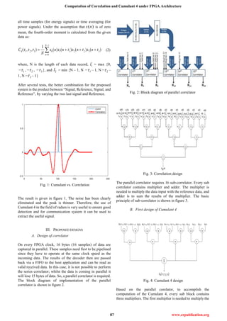
The figure 9 illustrates the results of the parallel
correlator. It can be seen that there are 16 correlations is
resulted on every FPGA clock cycle.
A. Cumulant 4
The comparison between the proposed designs of
Cumulant 4 is underway and the more efficient will be
simulated and then implemented in the FPGA card.
B. Properties of FPGA card
The ADM-XRC-5T1 is an FPGA card from Alpha-Data
which has a high performance PCI Mezzanine Card (PMC)
and designed for applications using Virtex-5 FPGAs from
Xilinx. This card communicates with the computer using a
PCI bridge developed by Alpha-Data which supports PCI-X
and PCI. So, a high speed multiplexed address/data bus
connects the computer to the FPGA. This card also uses a
Primary XMC connector to provide high-speed serial
connections. Figure 10 shows the physical board of
ADM-XRC-5T1 card.
Fig. 10: ADM-XRC-5T1 card
The ADM-XRC-5T1 supports high performance PCI-X
PCI operation without the need to integrate proprietary cores
into the FPGA:
Physically conformant to VITA 42 XMC Standard
Physically conformant to IEEE P1386-2001 Common
Mezzanine Card standard
8-lane PCIex / Serial Rapid IO connections to User
FPGA
8 additional MGT links to User FPGA
High performance PCI and DMA controllers
Local bus speeds of up to 80 MHz
Two independent banks of 64Mx32 DDRII SDRAM
(512 MB total)
One bank of 2Mx18 DDRII SSRAM (4 MB total)
V. CONCULSION AND PROSPECTS
In this paper, an FPGA based design for computing the
fourth-order cross moments is presented. The algorithm was
implemented on Xilinx Virtex-5 FPGA and the ADC S4/3G
that has sampling speed rate up to 3 GSPS. The maximum
operating speed of the design as reported by the ISE tool is
375 MHz.
For efficient and high-speed computation of
fourth-order cross moments under real-time constraints, the
employment of FPGA technology has proven to be an
attractive alternative.
For further developer, this is an interesting challenge to
develop under FPGA.
REFERENCES
[1] L. Sakkila, “Study and implementation of an ultra-wide-band radar
aimed to obstacle detection and recognition in road environments”,
PhD thesis, University of Valenciennes and Hainaut Cambrsis,
December 2009.
[2] C. L. Nikias and A. P. Petropulu, Higher-Order Spectra Analysis : A
Nonlinear Signal Processing Framework. Englewood Cliffs, New
Jersey: Prentice Hall, 1993.
[3] E.S. Manolakos, H.M. Stellakis and D. H. Brooks, “Parallel
processing for Biomedical signal processing,” IEEE Computer, vol.
24, No.3, 1991, pp. 33–43
[4] S. A. Alshebeili, “Computation of higher-order cross moments
based on matrix multiplication, Journal of the Franklin Institute, 338,
2001, pp. 811-816.
[5] Syed Manzoor Qasim, Ateeq Ahmad Khan, Saleh Alshebeili and Shuja
Ahmad Abbasi, “FPGA Based Architecture for the Computation of
Fourth-Order Cross Moments”, International Conference on
Intelligent and Advanced Systems, 2007
[6] L. Sakkila, Y. Elhillali, J. Zaidouni, A. Rivenq, C. Tatkeu, J.M
Rouvaen, High order statistic receiver applied to UWB radar, IEEE
Pacific Rim Conference on Communications, Computers and Signal
Processing, 2009](https://image.slidesharecdn.com/ijetr042170-200501112557/85/Ijetr042170-5-320.jpg)

This paper presents an FPGA-based design for high-speed computation of fourth-order cross moments, critical for digital signal processing, particularly in adaptive filtering and communication systems. The design, implemented in VHDL on a Xilinx Virtex-5 FPGA, operates at a maximum frequency of 375 MHz, making it suitable for real-time processing requirements. Two parallel designs for cumulant computation are explored, highlighting the advantages of FPGAs in handling complex computations efficiently.