Download to read offline
![International Journal of Engineering and Technical Research (IJETR)
ISSN: 2321-0869 (O) 2454-4698 (P), Volume-5, Issue-4, August 2016
61 www.erpublication.org
Abstract—The influence of delta wing vortex generators on
the wall of rectangular duct has been investigated in this study.
The angle of attack of vortex generators systematically varied in
this study to determine it’s effect on the heat transfer within the
rectangular duct of hydraulic diameter. The effect of delta wing
vortex generators at different angle of attack on pressure drop,
heat transfer coefficient, friction factor, Nusselt number are
reported for the Reynolds number based on the duct hydraulic
diameter in the range of 8000-20000. The experimental results
obtained with vortex generator is placed in comparison with the
experimental results obtained by without vortex generator to
define heat transfer enhancement factor in a duct. The
experimental results of the present study for friction factor and
Nusselt number in smooth rectangular duct agree well with
values estimated from correlations proposed by Blasius and
Dittus-Boelter respectively.
Index Terms—Heat transfer, Pressure drop, Delta wing type
of vortex generator, Nusselt number, Friction factor.
I. INTRODUCTION
In many of industrial engineering applications several
convective heat transfer methods are employed to improve the
thermal performance of heat transfer devices such as treated
surface, rough surface as well as incorporation of inserts like
vortex generators, turbulence promoters etc. Therefore the
heat transfer applications considering internal flow and mixed
convection in a non-circular ducts and channels have been
studied by many of researchers. For many of industrial
applications it becomes more essential to improve the heat
transfer coefficient and reducing pressure drop due limited
source of operation such as in heat exchangers, high
temperature gas turbine and electronic component.
For the enhancement of heat in a rectangular duct channel
we are using passive method of heat enhancement technique,
which is again classified in to longitudinal wise and transverse
wise heat enhancement technique. Vortex generator is one of
the method of insertion type which is found to enhancing the
heat in a variety of industrial applications.
A vortex generator is considered as a passive flow control
device which modifies the boundary layer fluid motion
bringing momentum from the outer region into the inner
region. The basic principle of vortex generator is to induce the
secondary flow which will disturb the thermal boundary layer
developed along the wall and removes heat from the wall of
Nikhil Kamlapure, Mechanical Department, JSPM’s Jayawantrao
Sawant College of Engineering, Hadapsar, Pune-28, India, 8605694880.
Prof. Shivanand Talwar, Mechanical Department, JSPM’s Jayawantrao
Sawant College of Engineering, Hadapsar, Pune-28, India, 9527788907.
Prof. Dr. P. A. Patil, Mechanical Department, JSPM’s Jayawantrao
Sawant College of Engineering, Hadapsar, Pune-28, India, 9765542844.
the duct due to turbulence. The experiments were conducted
to study the heat transfer and pressure drop in a rectangular
duct channel by using the transverse type of delta wing vortex
generator.
The experimental study on the behavior of a unique
longitudinal vortex generator embedded in a developing
turbulent boundary layer with a zero pressure gradient.[1]
At
the punched longitudinal vortex generators in the form of
winglets in staggered arrangements were used to observe the
results of vortex formation, pressure distribution, velocity
field, temperature fields, local heat transfer distribution in a
heat exchanger and the global results for the oval tubes with
two to four staggered winglets presented and compared.[2]
The comparison of fully developed heat transfer and
friction factor characteristics has been made in the rectangular
duct channel with roughened at five different shapes.[3]
The
implications of geometrical parameters of delta winglet
vortex generators on heat transfer and pressure loss
characteristics in a circular duct channel were evaluated.[4]
For the rectangular duct, the parameter examined were:
flow velocity from 0.5 to 3.4 m/s, Reynolds number from
3000 to 20,000 and results were reported with and without
mounting of the longitudinal vortex generators.[5]
The
decaying swirl flow was produced by the insertion of vortex
generators with propeller type of geometry and at three
different positions of the vortex generator in the axial
direction are examined.[6]
The heat transfer and pressure drop performance of a
full-scale heat exchanger was studied before and after
addition of wing type of vortex generators in two different
configurations and also examined the winglet configurations
at single vortex generator pair at the leading tube and three
vortex generator array placed at alternate tubes.[7]
The
experimental study of flow structure in horizontal equilateral
triangular ducts having double rows of half delta wing type of
vortex generators mounted on the duct.[8]
This paper deals
with heat transfer enhancement and pressure loss penalty
inside a rectangular duct with a delta wing type of vortex
generator.
II. DESCRIPTION OF EXPERIMENTAL SETUP
Experiments will be performed as per the figure depicted
in fig. 1. The experimental setup consists of a rectangular duct
channel of hydraulic diameter of 300mm and length of
900mm and for measuring the pressure of test section through
two pressure taps. Air blower provides air at the inlet of the
duct passed through flow control valve and an orifice-meter.
A simple U-tube manometer is used to measure the pressure
heads across the duct channel.
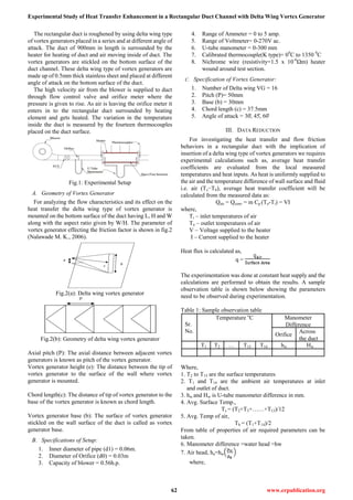
Experimental Study of Heat Transfer Enhancement in
a Rectangular Duct Channel with Delta Wing Vortex
Generator
Nikhil Kamlapure, Prof. Shivanand Talwar, Prof. Dr. P. A. Patil](https://image.slidesharecdn.com/ijetr042336-200501120820/85/Ijetr042336-1-320.jpg)
![International Journal of Engineering and Technical Research (IJETR)
ISSN: 2321-0869 (O) 2454-4698 (P), Volume-5, Issue-4, August 2016
63 www.erpublication.org
ρw= Density of water = 1000 kg/m3
Flow rate of air through Orifice-meter,
Qa= Cd
where,
A1 = Area of pipe
Ao = Area of orifice
Cd = Co-efficient of discharge
Mass flow rate, =Qa x ρa
Velocity of air,V = Qa /A
where,
A= cross sectional area of pipe.
Heat carried out, Q = *Cp*(T14-T1)
h =
where,
h = heat transfer coefficient.
Ts = surface temperature
The Reynolds number based on duct hydraulic diameter is,
Re =
where,
V= velocity of the fluid.
Dh= Hydraulic Diameter of Duct
ν Kinematic viscosity of the fluid.
The experimental Nusselt number is calculated as:
Nu = hD/k
Where,
h = heat transfer coefficient
k = thermal conductivity of fluid
D = diameter of test section i.e. Hydra. diameter
For the internal flow if Reynolds number (Re) exceeds by
4000 then the flow is turbulent. Once the type of flow is
decided then the Nusselt number can be calculated. The
theoretical Nusselt number can be calculated (i.e. without
considering friction) and then calculated by considering
friction which will be experimental Nusselt number,
Nuth = 0.023*(Re) 0.8
*(Pr)0.4
This equation is called Dittus-Boelter equation.
fs = (1.82 log10Re-1.64
)-2
This equation is used to find friction factor called as Petukhov
equation for smooth surface.
where,
fs= Friction factor for smooth tube.
Re= Reynolds number.
The actual pressure drop & friction factor is calculated with
the help of tapping at both the ends of test pipe connected to
U-tube manometer.
The friction factor is calculated from the formula given
below:
f =
where,
ΔP pressure difference at both ends of test pipe.
L= length of test section.
The friction factor for the fully developed turbulent flow in
smooth duct (104
< Re < 106
) is given by Blasius equation as,
f = 0.046Re-0.2
The thermal performance enhancement factor, defined as the
ratio of the heat transfer coefficient of a duct with VG, h to
that of a smooth duct, ho, at an equal pumping power is given
by:
TEF η
By using above methodology for the calculation of heat
transfer and pressure drop will be carried out for determining
the heat transfer enhancement for the defined duct channel.[9]
IV. RESULTS AND DISCUSSIONS
A. Performance evaluation
The experimental results on heat transfer and friction factor
in a rectangular duct are first of all obtained for the Nusselt
number and friction factor, by using Dittus-Boelter and
Blasius equation. Meanwhile the heat loss, Reynold’s
number, heat transfer coefficient is calculated for different
angle of attack of vortex generator.
The Nusselt number ratio i.e. Nu/Nu0, defined as ratio of
implication of insertion Nusselt number to the Nusselt number
of smooth rectangular duct.
The isothermal friction factor i.e. f/f0, defined as
implication of insertion friction factor to the friction factor of
smooth rectangular duct. Finally, the graph of Reynold’s
number v/s heat transfer coefficient, Reynold’s number v/s
Nusselt number, Reynold’s number v/s friction factor were
plot to determine the thermal performance enhancement
within duct at different angle of attack of Vortex Generator
A. Reynold’s Number v/s heat transfer coefficient:
Graph 1: Re v/s h
The plot of Reynold’s number v/s heat transfer coefficient at
different angle of attac of vortex generator to discuss the heat
transfer in a duct and will be observed maximum at 0 of
vortex generator due to proper mixing of a fluid in a duct
because of the increased blockage of a fluid within the duct
will increase the mixed fluid convection and as a result the
heat transfer coefficient of a duct is increased.
B. Friction factor ratio for rectangular duct:
For the rectangular duct from the number of readings were
taken by placing the vortex generator of different angle of
attac , the friction factor value for 0, , 0 was reported and
compared in above plot. Now the friction factor for vortex](https://image.slidesharecdn.com/ijetr042336-200501120820/85/Ijetr042336-3-320.jpg)
![Experimental Study of Heat Transfer Enhancement in a Rectangular Duct Channel with Delta Wing Vortex Generator
64 www.erpublication.org
generator at different angle of attack is compared with smooth
rectangular duct without vortex generator.
Graph 2: Re v/s fcal/fb
The ratio of friction factor with vortex generator to without
vortex generator calculated by Blasius is compared to
determine the increase or decrease in friction factor for a used
insert with reference to smooth duct. If the friction factor ratio
for the inserts is low then the vortex generator is best suited
for the designed duct of defined dimensions. The graph shown
above discusses the friction factor ratio with inserts with
reference to smooth duct against the Reynold’s number.
C. Nusselt number ratio for rectangular duct:
The ratio of Nusselt number with vortex generator to
without vortex generator calculated by Dittus-Boelter is
compared to determine the increase or decrease in heat
transfer for a used insert with reference to smooth duct. If the
Nusselt number ratio for the inserts is greater then the vortex
generator is best suited for the duct of defined dimensions.
The graph shown below discusses the Nusselt number ratio
with inserts with reference to smooth duct against the
Reynold’s number.
Graph 3: Re v/s Nucal/NuDB
D. Thermal Enhancement Factor(TEF):
For the proposed test section the thermal enhancement
factor should be always more than 1, if it less than 1 then
inserts or duct is redesigned and if it is more than 1 then the
heat transfer enhancement method is preferred for the
designed duct dimensions.
Graph 4: Thermal Enhancement Factor
V. CONCLUSION
An experimental study was performed to determine the
airflow friction inside the rectangular duct, heat transfer
coefficient and enhancement in heat from the duct by, the
implication of insertions like transverse type of delta wing
vortex generator at different angle of attack. From the results
of friction factor and Nusselt number we can clearly describe
the heat transfer enhancement in a rectangular duct channel
with and without vortex generator. Amoung different angle of
attac of vortex generator the Nusselt number, Reynold’s
number, heat transfer coefficient and friction factor variation
was seen best suited at an angle of 0 of vortex generator.
Meanwhile the Thermal Enhancement Factor(TEF) was also
found to be highest at lower Reynold’s number.
REFERENCES
[1] Shakaba, Mehta R. D., and Bradshaw P., (1985), Longitudinal
vortices embedded in turbulent boundary layers. Part 1. Single vortex,
J. Fluid Mech., Vol. 155, pp 37-57.
[2] Chen Y, Fiebig M, Mitra N.K, (2000), Heat transfer enhancement of
finned oval tubes with staggered punched longitudinal vortex
generators, International Journal of Heat and Mass Transfer 43,
pp.417-435.
[3] Ahn S. W., (2001), The effect of roughness types on friction factors
and heat transfer in roughened rectangular duct, Heat Mass Transfer,
vol. 28, No. 7, pp. 933-942.
[4] Yakut K, Sahin B, Celik C, Alemdaroglu N, and Kurnuc A, (2005),
Effects of tapes with double-sided delta-winglets on heat and vortex
characteristics, Applied Energy, Vol. 80, pp 77–95.
[5] Qiuwang Wang, Qiuyang Chena, Ling Wang, Min Zenga, Yanping
Huangc, Zejun Xiao, (2007), Experimental study of heat transfer
enhancement in narrow rectangular channel with longitudinal vortex
generators, Nuclear Engineering and Design, vol.237, pp. 686–693.
[6] Betu Ayhan Sarac, Tulin Bali, (2007), An experimental study on heat
transfer and pressure drop characteristics of decaying swirl flow
through a circular pipe with a vortex generator, Experimental
Thermal and Fluid Science, Vol.32, pp.158–165.
[7] Joardar A, Jacobi A.M., (2008), Heat transfer enhancement by
winglet-type vortex generator arrays in compact plain-fin-and-tube
heat exchangers, International journal of refrigeration 31, pp.87 –
97.
[8] Azize Akcayoglu, (2010), Flow past confined delta-wing type vortex
generators, Experimental Thermal and Fluid Science, Vol.35,
pp.112–120.
[9] Pongjet Promvonge, Sompol Skullong, Sutapat Kwankaomeng,
Chinaruk Thiangpong, (2012), Heat transfer in square duct fitted
diagonally with angle-finned tape.Part 1: Experimental study,
International Communications in Heat and Mass Transfer 39, pp.
617–624.
Nikhil Kamlapure is pursuing his Post Graduation in Heat-Power
(Mechanical Department) from JSPM’s Jayawantrao Sawant College of
Engineering, Hadapsar, Pune-28, India. He has completed his B.E. from
University of Pune in 2014.
Prof. Shivanand Talwar is Assistant Professor in Department of
Mechanical Engg., JSPM’s Jayawantrao Sawant College of Engineering,
Hadapsar, Pune-28, India. He has 05 years of teaching experience and 01
year industrial experience. He has completed his M.Tech (Thermal) form
VTU Belgaon, India.
Prof. Dr. P. A. Patil is Head of Mechanical Engineering Department,
JSPM’s Jayawantrao Sawant College of Engineering, Hadapsar, Pune-28,
India. He has 19 years of teaching and 1 year industrial experience. His area
of specialization is in Refrigeration and Air-Conditioning, Fluid Mechanics
and Heat Transfer.](https://image.slidesharecdn.com/ijetr042336-200501120820/85/Ijetr042336-4-320.jpg)

This study investigates the influence of delta wing vortex generators at varying angles of attack on heat transfer and pressure drop in a rectangular duct. Experimental results show that the presence of vortex generators enhances heat transfer and affects the friction factor and Nusselt number, with optimal performance observed at an angle of 0 degrees. The comprehensive analysis includes calculations of heat transfer coefficients, Nusselt numbers, and thermal enhancement factors to evaluate heat transfer efficiency in the duct.


