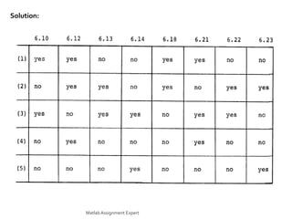
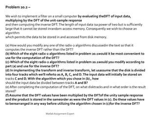
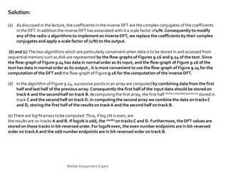
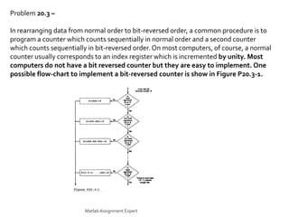
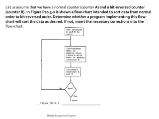
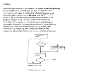
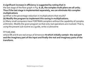
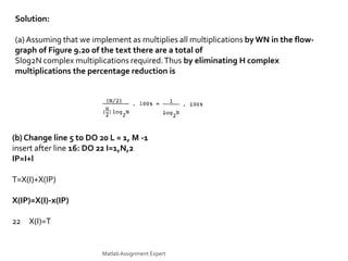
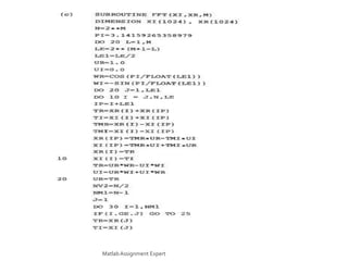
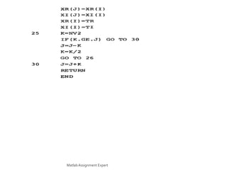
This document discusses the computation of the discrete Fourier transform (DFT) using radix-2 fast Fourier transform (FFT) algorithms. It provides information on decimation-in-time and decimation-in-frequency algorithms, and discusses properties like whether the algorithms are in-place, whether input/output is in normal order, and whether coefficients need to be stored in bit-reversed order. It also contains problems and solutions related to implementing DFTs and FFTs, including modifying algorithms, rearranging data, and optimizing programs to reduce computations.
Enzyme, Pharmaceutical Aids, Miscellaneous Last Part of Chapter no 5th.pdf
Â
Fourier Transform Assignment Help
1. Computation of the Discrete Fourier
Transform
For Any Quarries or info, Contact us on : +1 678 648 4277
You can Mail us on : info@matlabassignmentexperts.com
Visit us on : https://www.matlabassignmentexperts.com/
MatlabAssignment Expert
2. Problem 20.1 –
The basic radix-2 FFT algorithms based on decimation-in-time are
indicated in the text, Figures 9.10, 9.14, 9.15, 9.16.The basic
radix-2 FFT algorithms based on decimation-in-frequency are
indicated in the text Figures 9.20, 9.22, 9.23, 9.24. For each
of these eight flow-graphs indicate whether or not each of the
following properties is true or not:
(1) Represents an in-place computation
(2) Input is in normal order
(3) Output is in normal order
(4) Coefficients should be stored in bit-reversed order
(5) Accessing of the data is identical for every array
MatlabAssignment Expert
4. Problem 20.2 –
We wish to implement a filter on a small computer by evaluating theDFT of input data,
multiplying by the DFT of the unit-sample response
and then computing the inverse DFT.The length of input data isa power of two but is sufficiently
large that it cannot be stored inrandom-access memory. Consequently we wish to choose an
algorithm
which permits the data to be stored in and accessed from disk memory.
(a) How would you modify any one of the radix-2 algorithms discussedin the text so that it
computes the inverse DFT rather than the DFT?
(b)Which of the eight radix-2 algorithms listed in problem 20.1would it be most convenient to
use for the computation of the DFT?
(c)-Which of the eight radix-2 algorithms listed in problem 20.1would you modify according to
part (a) and use for the inverse DFT?
(d) In implementing the transform and inverse transform, let usassume that the disk is divided
into four tracks which we'll referto as A, B, C, and D.The input data will initially be stored on
tracks C and D.With the algorithm which you chose in (b) , how
should the input data be divided between tracks A and B?
(e) After completing the computation of the DFT, on what disktracks and in what order is the result
stored?
(f) Assume that the DFT values have been multiplied by the DFTof the unity sample response
and the product is stored in the sameorder as were the DFT values in (c). Do these values have
to berearranged in any way before utilizing the algorithm chosen in (c)for the inverse DFT?
MatlabAssignment Expert
5. Solution:
(a) As discussed in the lecture, the coefficients in the inverse DFT are the complex conjugates of the coefficients
in the DFT. In addition the inverse DFT has associated with it a scale factor of1/N. Consequently to modify
any of the radix-2 algorithms to implement an inverse DFT, we replace the coefficients by their complex
conjugates and apply a scale factor of (1/N) to the output.
(b) and (c) The two algorithms which are particularly convenient when data is to be stored in and accessed from
sequential memory such as disk are represented by the flow-graphs of Figures 9.16 and 9.24 of the text. Since
the flow-graph of Figure 9.24 has data in normal order as its input, and the flow-graph of Figure 9.16 of the
text has data in normal order as its output , it is most convenient to use the flow-graph of Figure 9.24 for the
computation of the DFT and the flow-graph of Figure 9.16 for the computation of the inverse DFT.
(d) In the algorithm of Figure 9.24, successive points in an array are computed by combining data from the first
half and last half of the previous array. Consequently the first half of the input data should be stored on
track A and the second half on track B. In computing the first array, the first half of the computed points are stored in
track C and the second half on track D. In computing the second array we combine the data on tracks C
and D, storing the first half of the results on track A and the second half on track B.
(e)There are log2N arrays to be computed.Thus, if log 2N is even, are
the results are on tracks A and B. If log2N is odd, the results on tracks C and D. Furthermore, the DFT values are
stored on these tracks in bit-reversed order. For log2N even, the even number endpoints are in bit-reversed
order on track A and the odd number endpoints are in bit-reversed order on track B.
MatlabAssignment Expert
6. (f) The algorithm of Figure 9.16 which is to be used for the
inverse transform assumes that the input is in bit-reversed order.
Consequently it is not necessary to sort the DFT values into normal
order. In the algorithm of Figure 9.16 the computation of an array
involves combining successive points in the previous array to obtain results in the first half and last half of the
array being computed.Assume that the results from the computation of the DFT are stored on tracks A and B. As
discussed in (e), the first half of
these points (the even numbered points) are on track A and the second half (the odd numbered points) are on
track B.
In implementing the flow-graph of Figure 9.16 we first combine
successive points from track A generating results for the first and
last half of the first array. When track A is completed, we
combine successive points from track B.Thus in using the output of
the flow-graph of Figure 9.24 as the input to the flow-graph of Figure 9.16 no rearrangement of data is
necessary.The way in which data is accessed and stored is however different for the two algorithms
MatlabAssignment Expert
7. Problem 20.3 –
In rearranging data from normal order to bit-reversed order, a common procedure is to
program a counter which counts sequentially in normal order and a second counter
which counts sequentially in bit-reversed order. On most computers, of course, a normal
counter usually corresponds to an index register which is incremented by unity. Most
computers do not have a bit reversed counter but they are easy to implement. One
possible flow-chart to implement a bit-reversed counter is show in Figure P20.3-1.
MatlabAssignment Expert
8. Let us assume that we have a normal counter (counter A) and a bit-reversed counter
(counter B). In Figure P20.3-2 is shown a flow-chart intended to sort data from normal
order to bit-reversed order. Determine whether a program implementing this flow-
chart will sort the data as desired. If not, insert the necessary corrections into the
flow-chart.
MatlabAssignment Expert
9. Solution:
Let m denote a memory location (0 < m < N -1) and m the corresponding
bit-reversed location. According to the flow-chart of Figure P20.3-2
when counter A is equal to m, the data in locations m and m are
interchanged and when counter A is equal to m the data in locations
m and m are again interchanged. Consequently at the end of the
program in Figure P20.3-2 the data is still in normal order.To
correct this it is necessary to ensure that an exchange between a
memory location and its bit-reversed counterpart is made only once.
One possible correction to the flow-chart of Figure S20.3-1 is
indicated in Figure S20.3-1.This correction also takes into
account the obvious fact that when m = m no exchange is necessary.
MatlabAssignment Expert
10. Problem 20.4 –
Draw the flow diagram for a nine-point (i.e., 3 x 3) decimation-in time FFT algorithm.
Solution:
With N = 9 we divide x(n) into three subsequences each containing three points as indicated in Figure S20.4-
1
Thus,
MatlabAssignment Expert
11. The resulting flow graph is shown in Figure S20.4-2
MatlabAssignment Expert
12. Problem 20.5 –
The FORTRAN program shown in Figure P20.5-1 is an implementation of the
decimation-in-frequency algorithm depicted in Figure 6.18 of the text.The program
evaluates the DFT:
MatlabAssignment Expert
13. In the subroutine FFT(X,M) X is a complex array of dimension N that contains
initially the input sequence x(n) and finally contains the transform X(k).The
quantity M is an integer, M = log2N.
This program is a straightforward implementation of the flow-graph of Fig. 9.20 of
the text.The program is very elegant but not as efficient as it could be. Greater
efficiency can be obtained at the cost of a more complex program.
MatlabAssignment Expert
14. A significant increase in efficiency is suggested by noting that in
the last stage of the flow graph in Fig. 6.18, the complex multi pliers are all unity.
Thus if the last stage is implemented separately, we can eliminate N/2 complex
multiplications
(a) What is the percentage reduction in multiplications that results?
(b) Modify the program to implement this saving in multiplications.
(c) Many small computers have FORTRAN compilers without the capability of complex
arithmetic. Modify the given program so that only real operations are involved.That is,
using the present sub routine as a guide, write a subroutine
FFT(XR,XIM)
where XR and XI are real arrays of dimension N which initially contain the real part
and the imaginary part of the input and finally the real and imaginary parts of the
transform.
MatlabAssignment Expert
15. Solution:
(a) Assuming that we implement as multiplies all multiplications by WN in the flow-
graph of Figure 9.20 of the text there are a total of
Slog2N complex multiplications required.Thus by eliminating H complex
multiplications the percentage reduction is
(b) Change line 5 to DO 20 L = 1, M -1
insert after line 16: DO 22 I=1,N,2
IP=I+l
T=X(I)+X(IP)
X(IP)=X(I)-x(IP)
22 X(I)=T
MatlabAssignment Expert