Download to read offline
![International Journal of Engineering and Technical Research (IJETR)
ISSN: 2321-0869, Volume-1, Issue-10, December 2013
95 www.erpublication.org
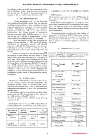
VI. HEAT CALCULATIONS
Q Description
For PUT 11640
kg/hr
Q1 Heat taken by PTA
Q2
Heat taken for PTA
dissolution
Q3
Heat taken by
feed EG
Q4
Heat taken
by water
Q5
Heat taken for EG
vaporization
Q6
Heat taken by water
vaporization
Q7
Heat taken to
heat oligomer
Q
TOTAL HEAT
LOAD
HEAT GIVEN BY
DOWTHERM
VII. ANALYSIS
The detailed energy balance calculations for CP4
heat indicate that the operation of the heat exchanger under
steady state condition is in order and the results are within the
limits of measurement and calculation errors.
The calculations does not account for unsteady state
situations like plant upsets. For e.g. plant shutdown and start
up, power or steam failure situations are not included in the
calculations.
Apart from the heat duty, there are some operating
constraints associated with the Heat Exchanger and vapor
separator unit. With the throughput of 280 TPD, the reactor
conditions are such that the carryover is very low. Presently,
fortnightly cleaning of pot filters is done which maintains the
solid content in the system. With increased throughput to 280
TPD, the vapor load and process conditions will lead to
increased carryover rate. Though the rate of carryover cannot
be exactly predicted, it can be seen that increasing the
cleaning frequency to once a week or even more will take care
of the system.
VIII. CONCLUSION AND RECOMMENDATIONS
CP4 esterification system works under steady state
operating condition. The heat exchange calculations have
been considered with high level and temperature operation.
The additional heat duty due to increased slurry flow rate and
higher temperature differential is being fulfilled by the same
heat exchanger.
It is recommended that with the increase in throughput, the
reactor carryover needs to be carefully watched and pot filter
cleaning frequency should be optimized to prevent process
upset due to choking. Feasibility of other equipments for
higher throughput 280 TPD (water condenser, seperation
column, UFPP Finisher) etc.can be studied.
REFERENCES
[1] Dupont’s Basic Data Manual.
[2] “PROCESS HEAT TRANSFER” BY D.Q KERN FIFTH Edition,
MCGraw Hill International Publication, (1988).
[3] Chemical Engineers portable hand book by Richard.G.Griskey,
McGraw Hill international publication, (2000)
[4] “Unit operations of Chemical Engineering” By Waren.l.McCabe,
Julian Smith and Peter Harriot.Sixth Edition, McGraw Hill
International Publication.(2001).
[5] “shell and Tube Heat Exchanger Design Software for Educational
Applications” by K.C. Leong and K.C.Toh, Int. J.Enging Ed. Vol. 14,
No.3, p.217-224,TEMPUS Publication,1998.
[6] “Effective Design Shell and Tube Heat Exchangers” by Rajiv
Mukherjee, Engineers India Ltd.
[7] “Applying Learnable Evolution Model to Heat Exchanger Design” by
Kenneth A. Kaufman and Ryszard S. Michalski Machine Learning and
Inference Laboratory .
Vikas Barfa, Student of Master of Engineering, RGPV Bhopal, M.P.
Specialisation in Thermal Engineering. Contact No. 09584686262.
Mr. A. Paul, Associate Professor Mechanical Engineering SSSIST
sehore M.P.
Dr. G.R.Selokar, Principal,SSSIST Sehore M.P](https://image.slidesharecdn.com/ijetr012053-171120162318/85/Ijetr012053-3-320.jpg)

The document discusses the design and heat balance analysis of a continuous polymerisation unit (CP-4) used for producing polyester staple fiber from purified terephthalic acid (PTA) and mono ethylene glycol (MEG). It details the heat exchanger's operation, necessary conditions for polyester production, and recommendations for maintaining system efficiency as throughput increases. The results indicate that the heat exchanger operates effectively under steady state conditions, but further monitoring and adjustments may be needed for optimal performance.