Downloaded 464 times

![DESIGN SUMMARY
Parameter Value
Operating temperature 100
Operating pressure (atm) 1
Material of construction Austenitic stainless steel Type 304L
Vessel internal diameter (m) 1.524
Vessel height (m) 2.65
Type of head and bottom Torispherical
Type of vessel Cylindrical
Vessel wall thickness (mm) 18
Stress analysis (N/mm2) (Δσ)max S < , (7.7128 < 137.89) [Safe]
Elastic stability (N/mm2)
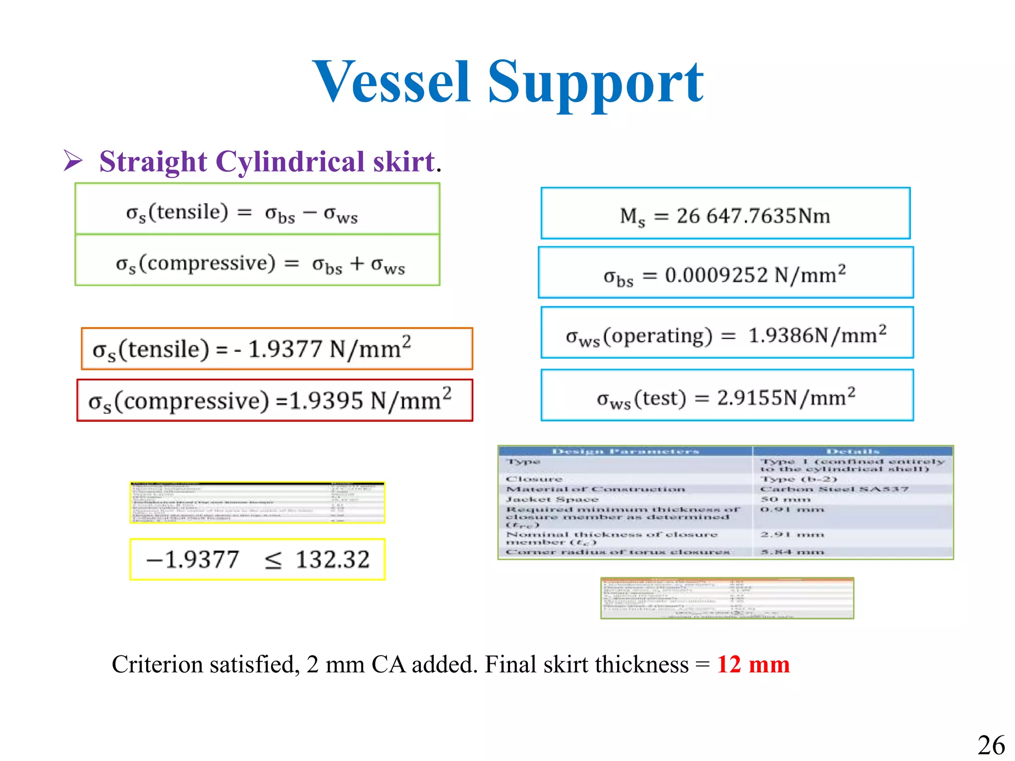
Type of vessel support Straight conical skirt
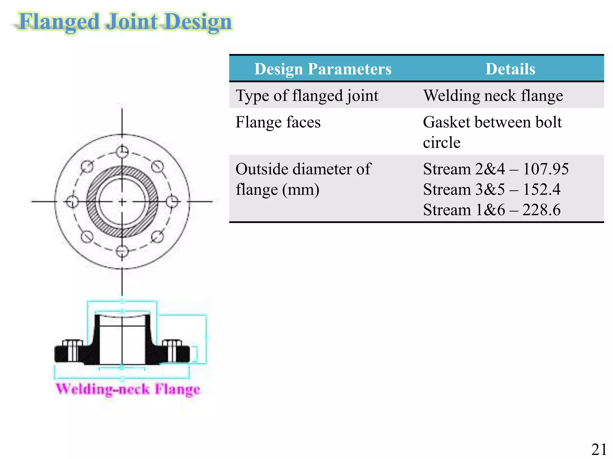
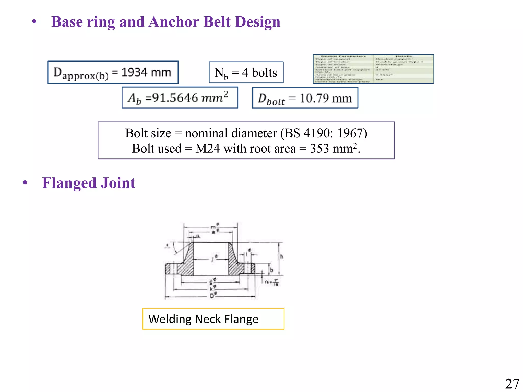
Type of flanged joint Welding neck flange
Flange faces Gasket between bolt circle
Flange diameter (mm) 50.8, 101.6, 660.4
34](https://image.slidesharecdn.com/kb4presentationsem2-140404115432-phpapp02/75/FYDP-Sem-2-34-2048.jpg)


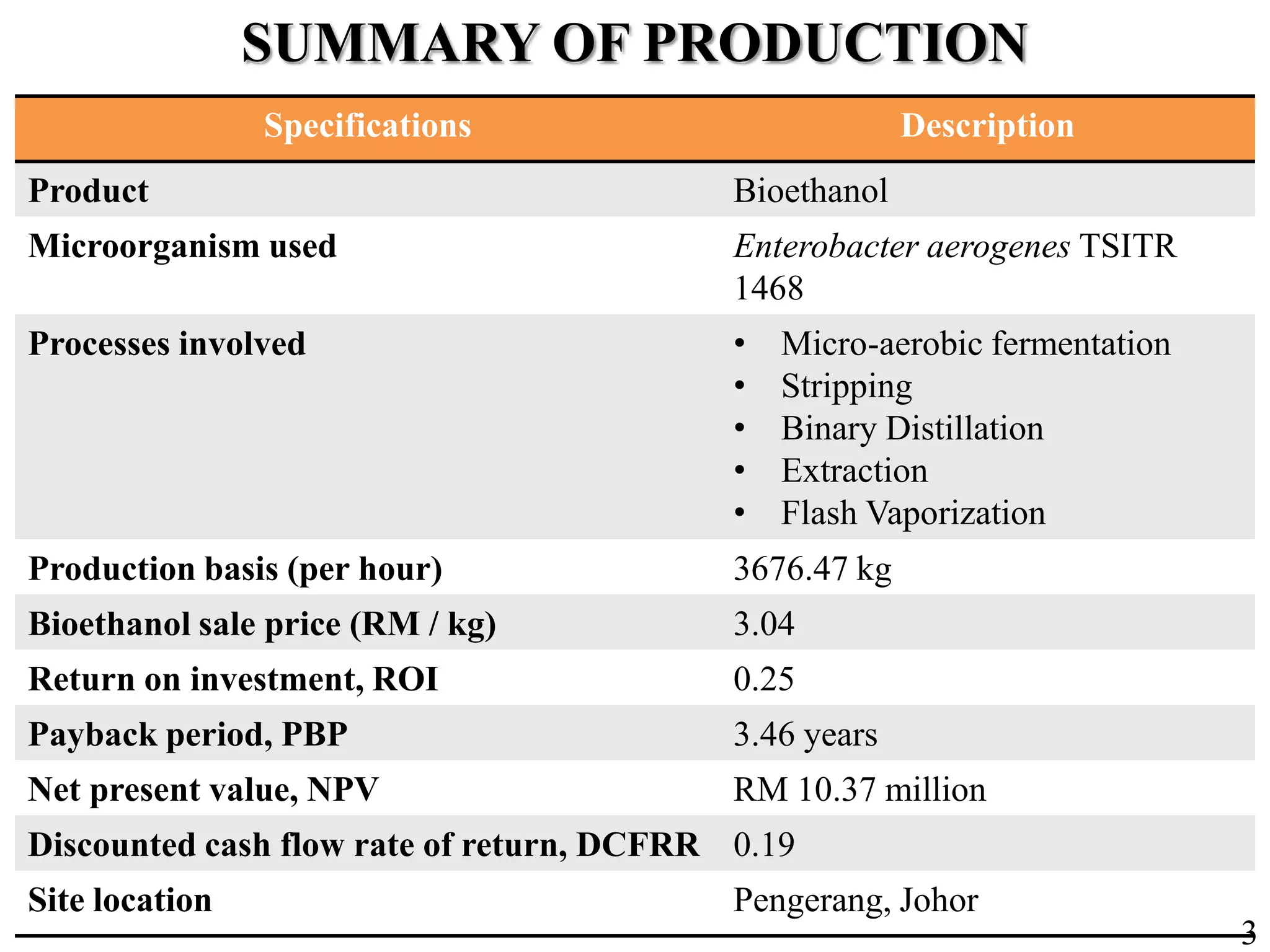
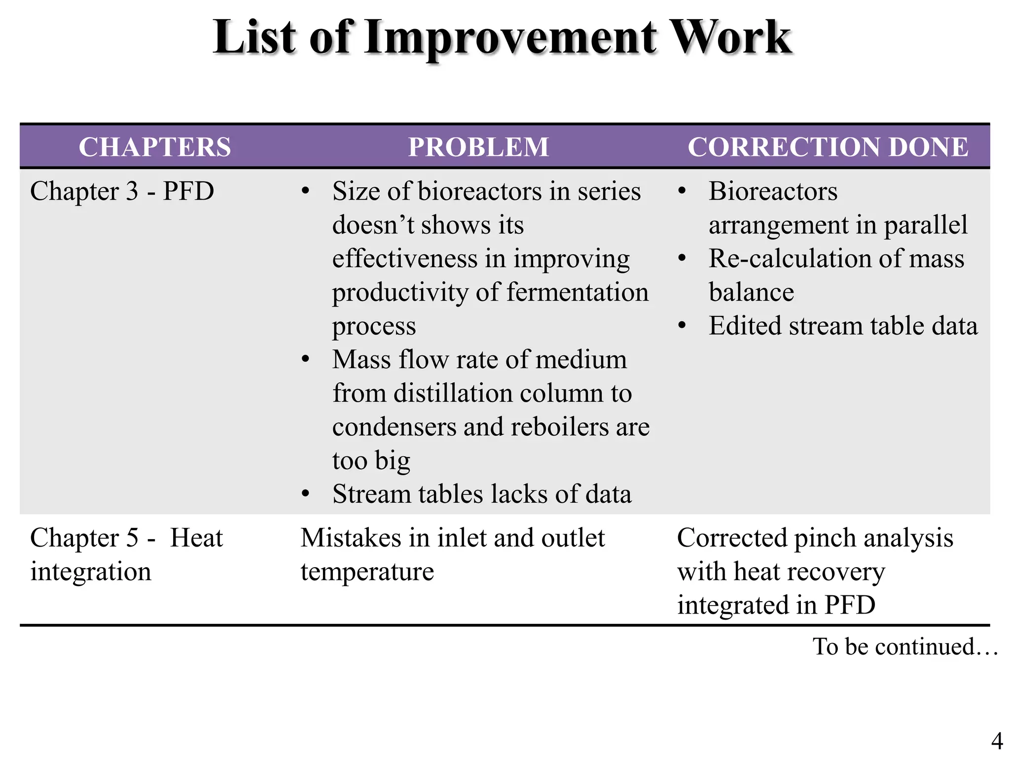
The document provides details of a project to produce bioethanol from glycerol using Enterobacter aerogenes TISTR1468. It summarizes the production process, which involves micro-aerobic fermentation, stripping, binary distillation, extraction, and flash vaporization. Key production metrics are given, such as a production rate of 3676.47 kg of bioethanol per hour. It also lists several chapters that require improvement work, such as redesigning the bioreactors, correcting heat integration calculations, completing control loops and relief valves on piping and instrumentation diagrams, and redesigning process units based on new stream data.
Introduction of group members and project topic on bioethanol production from glycerol.
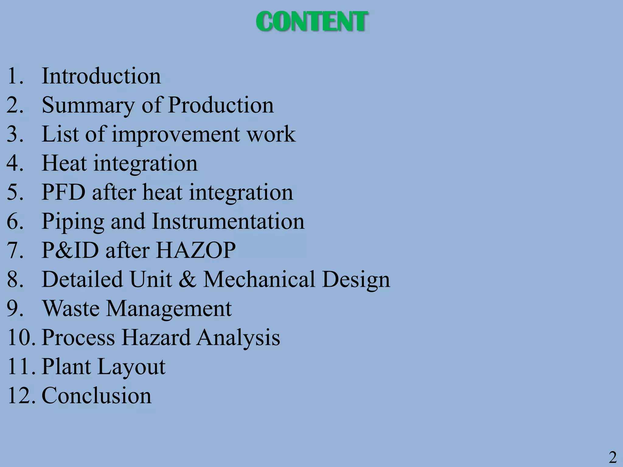
Outline of presentation contents including introduction, process design, waste management, and conclusion.
Overview of bioethanol production specifications using Enterobacter, including ROI, NPV, and sale price.
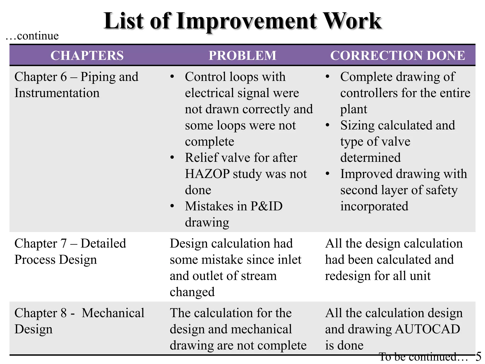
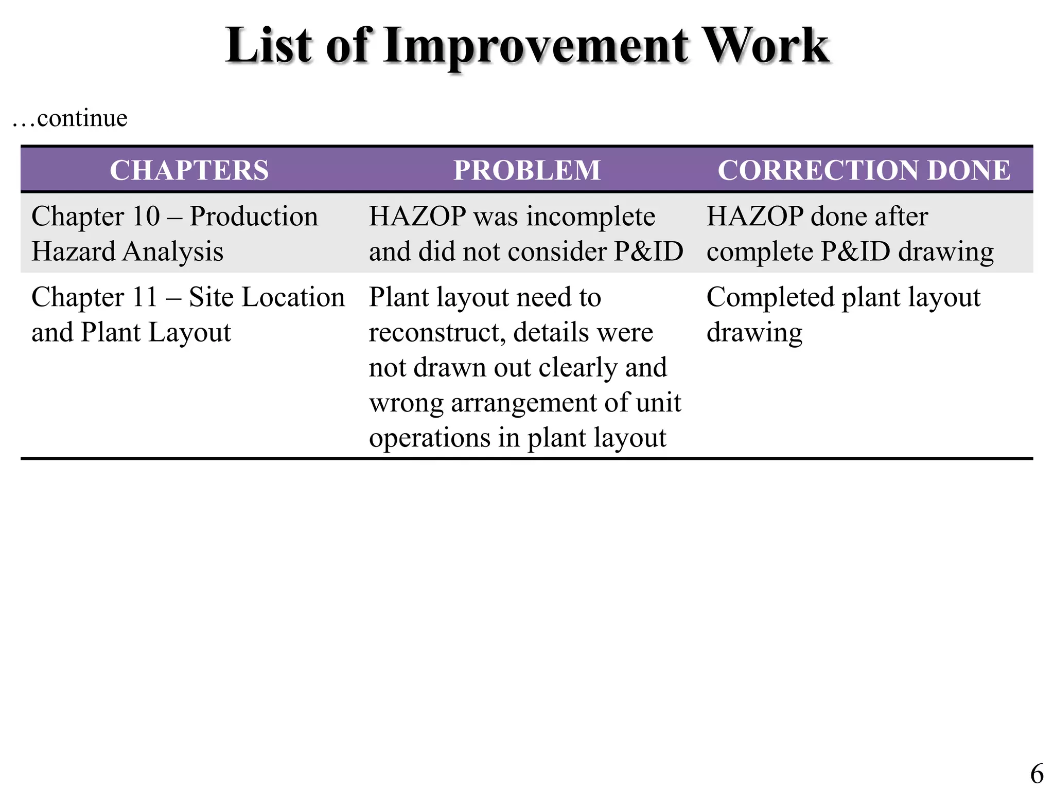
Correction of problems in various design chapters including PFD, heat integration, piping, and safety analysis.
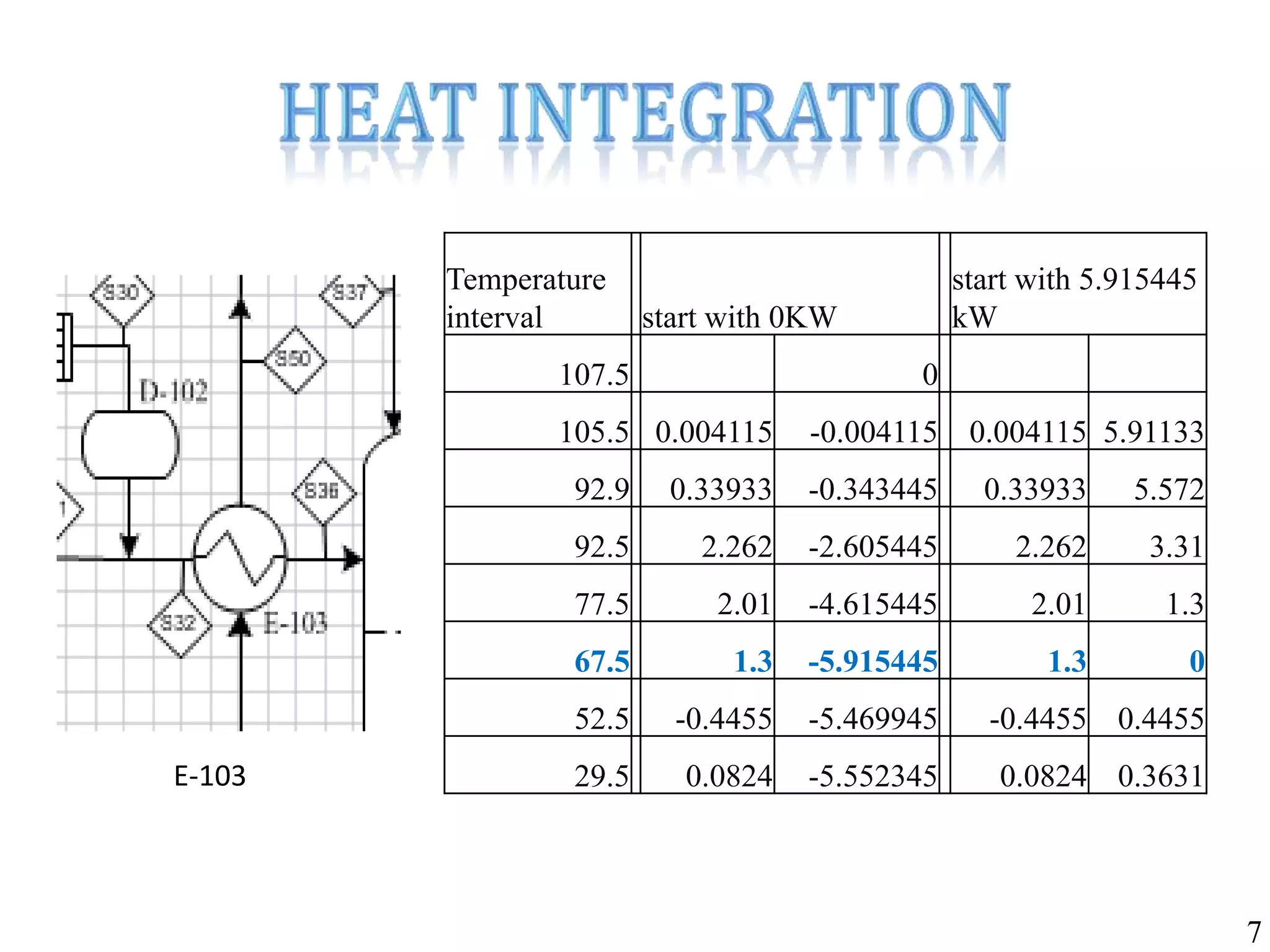
Temperature data related to various operational conditions and heat exchange calculations.
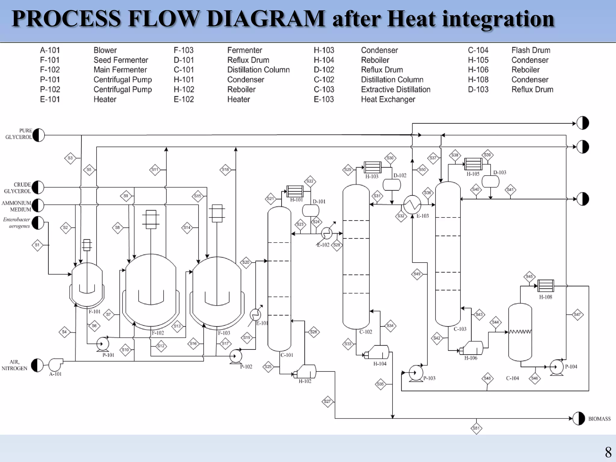
Process flow diagram (PFD) illustrating operation post-heat integration.
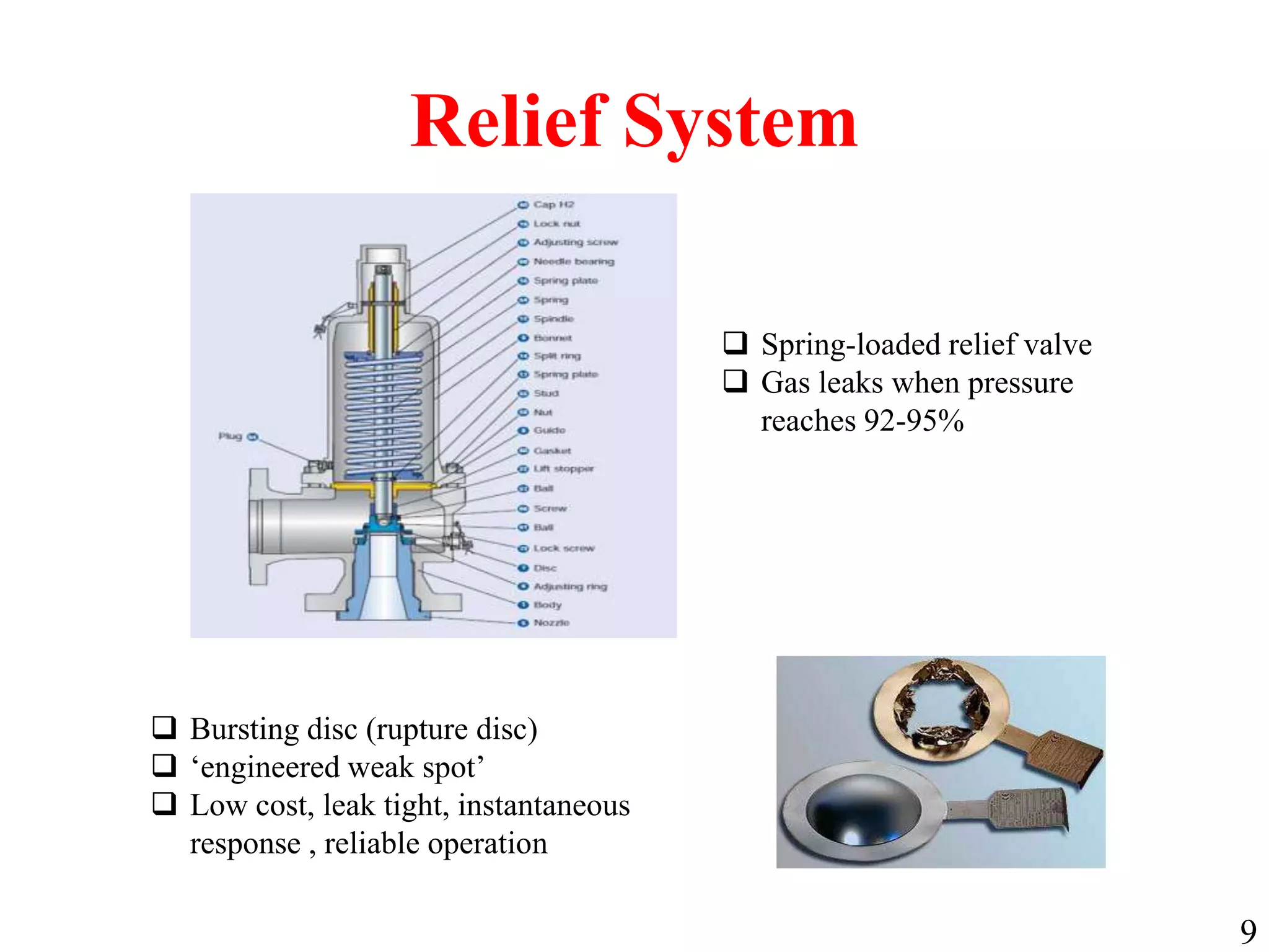
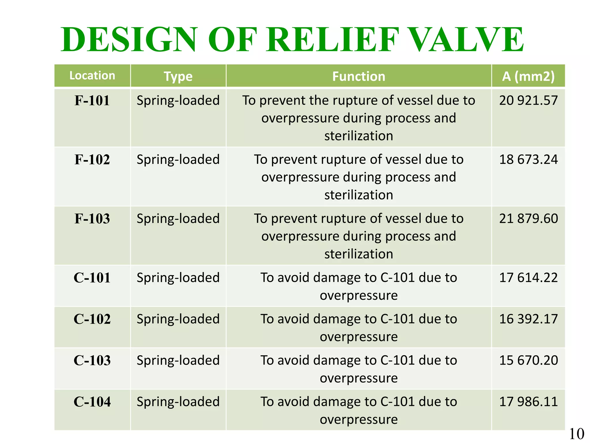
Details on the design and function of spring-loaded relief valves for pressure control in the system.
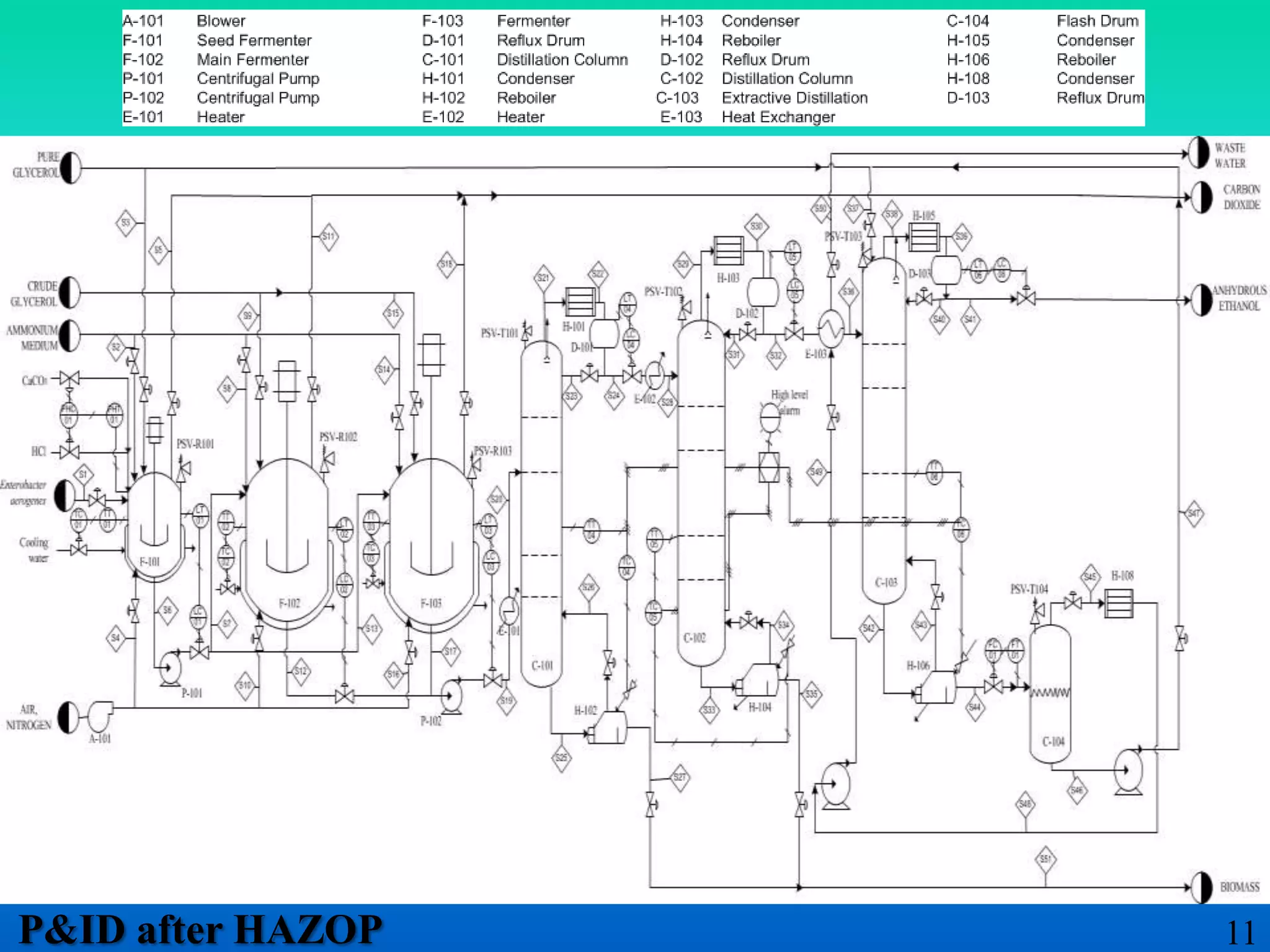
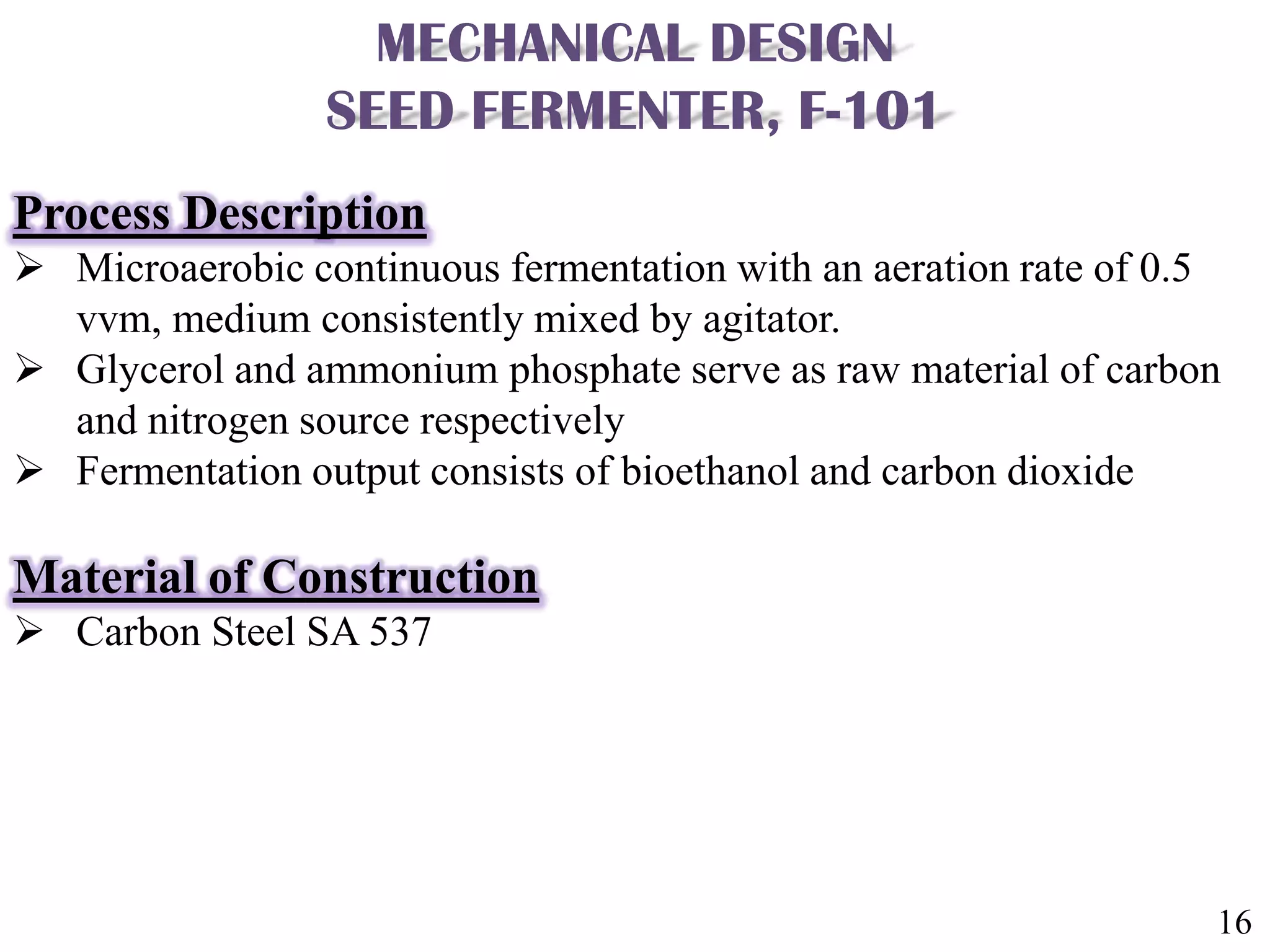
P&ID updates after HAZOP and detailed designs for key reactors and systems.
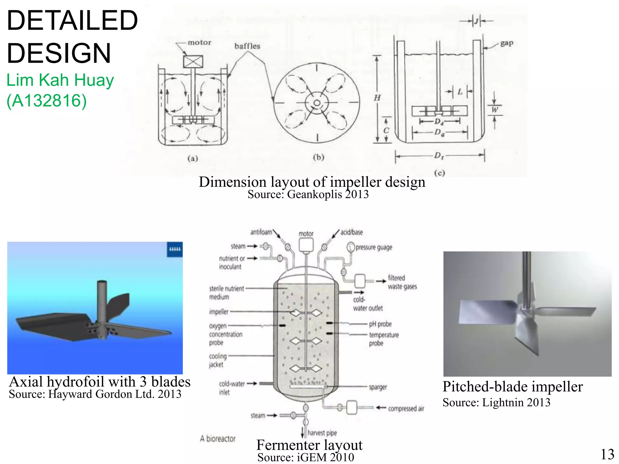
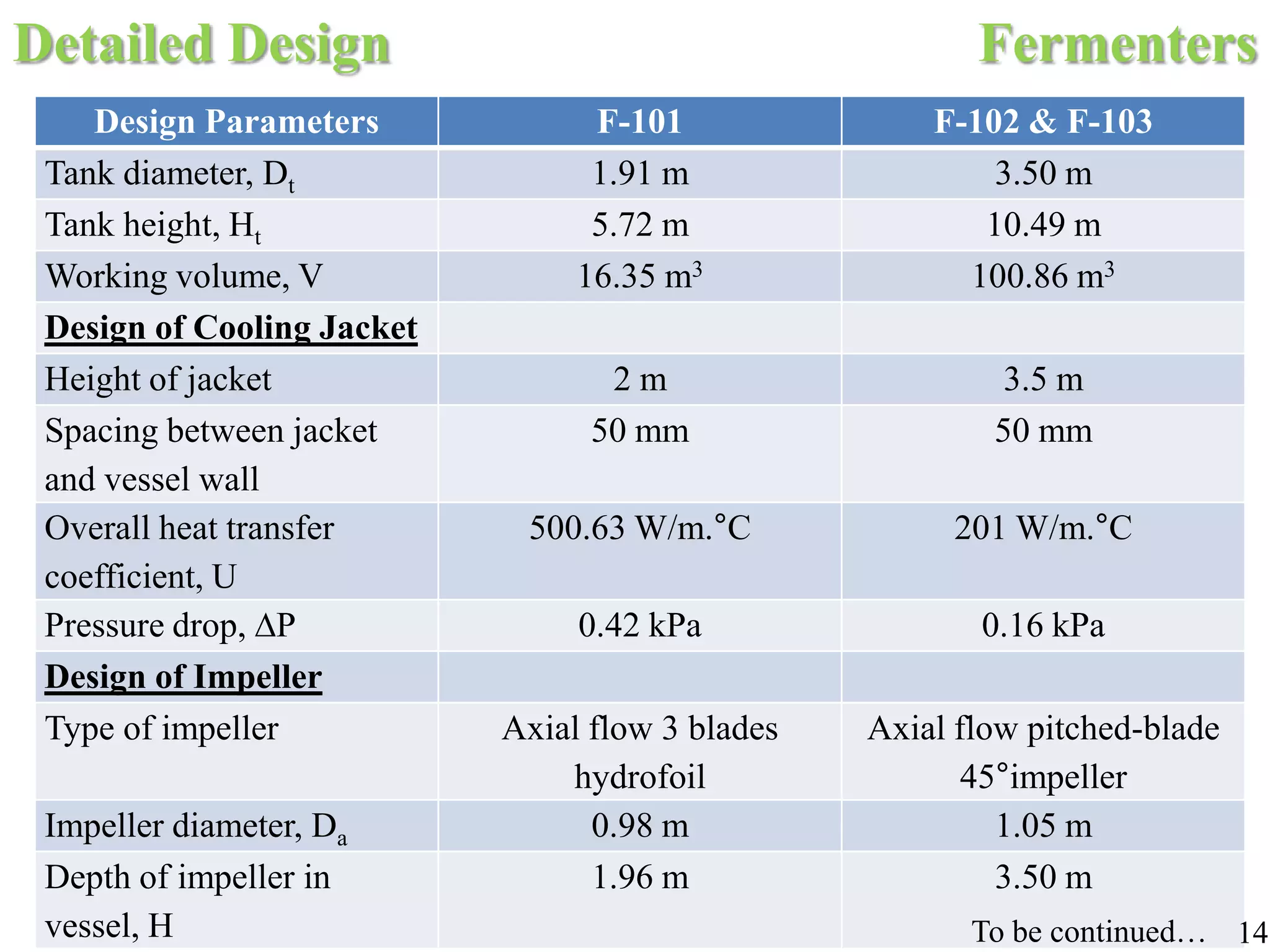
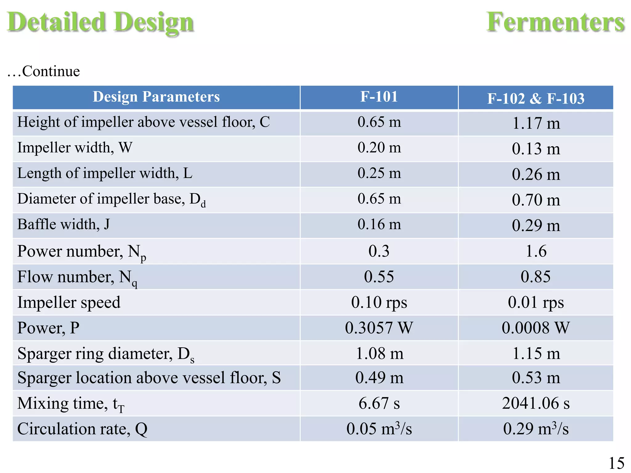
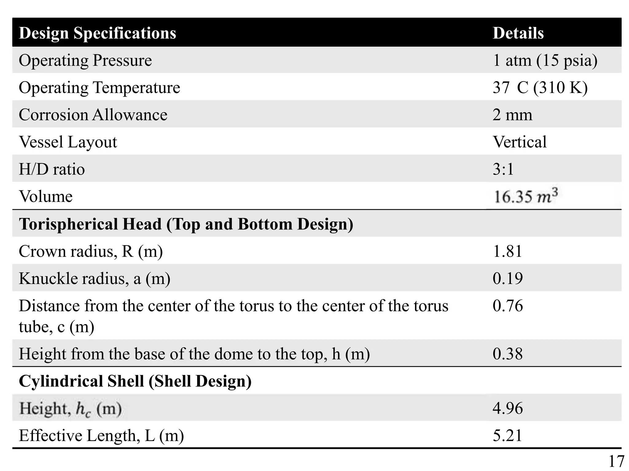
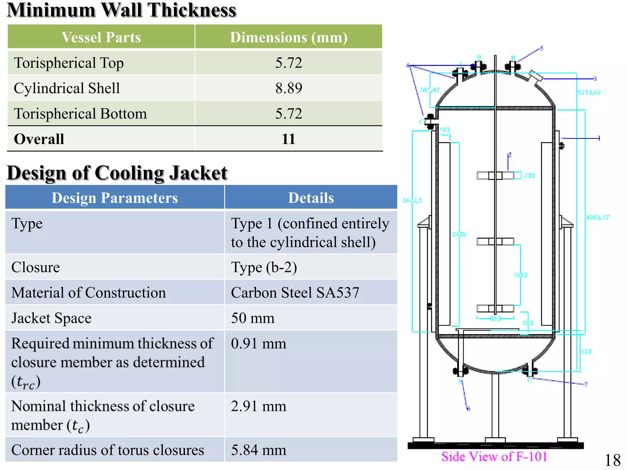
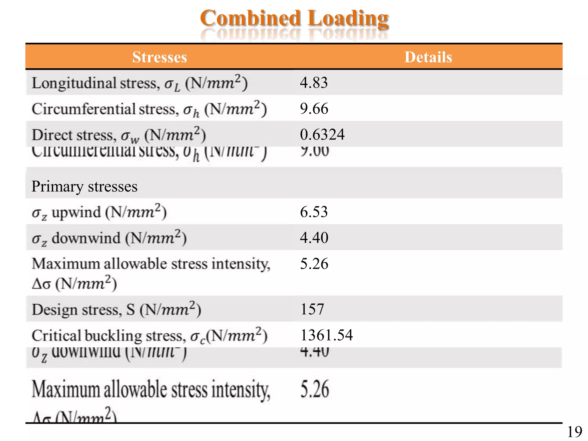
In-depth design parameters for fermenters, including impeller specifications and pressure/stress analysis.
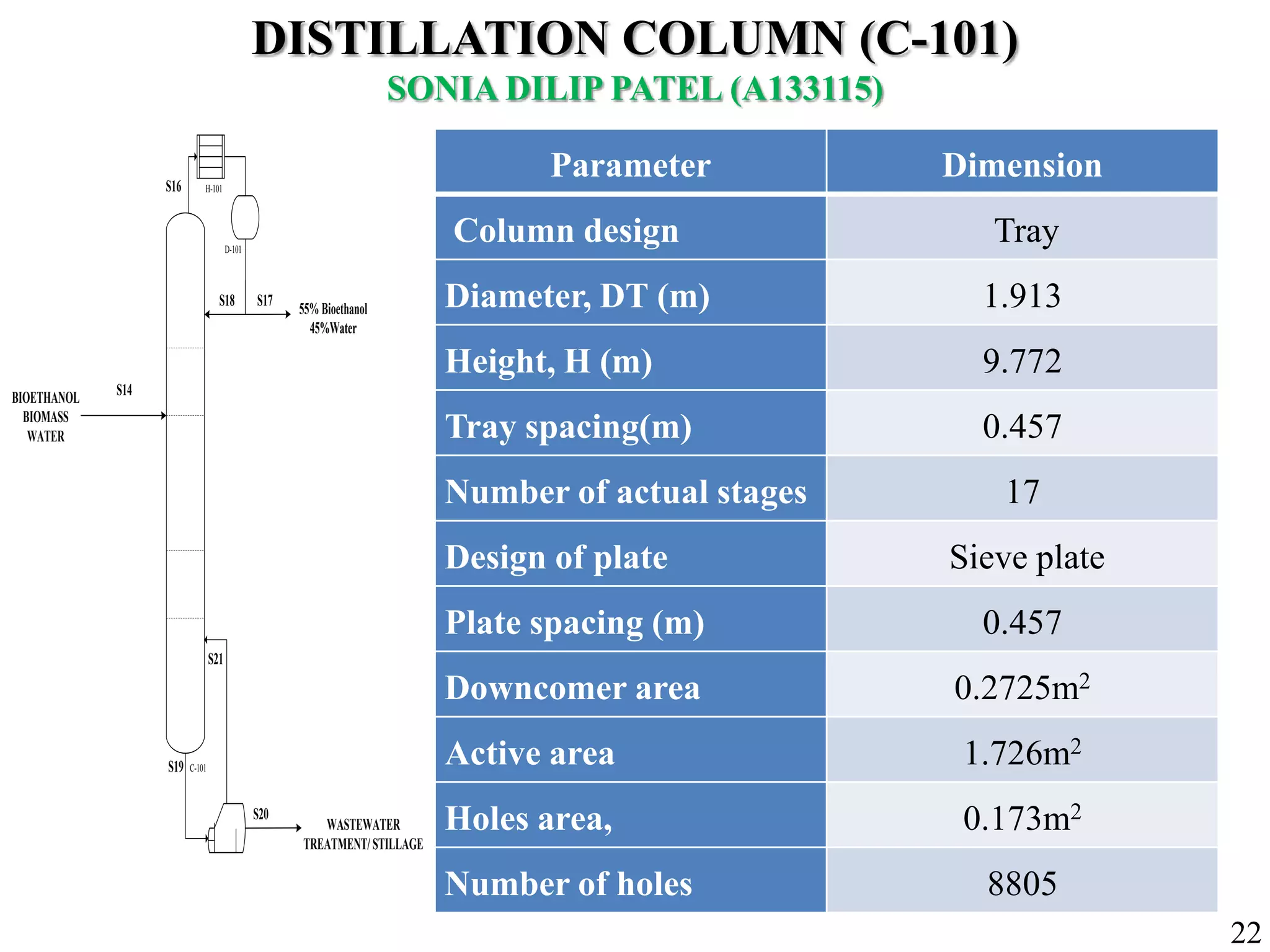
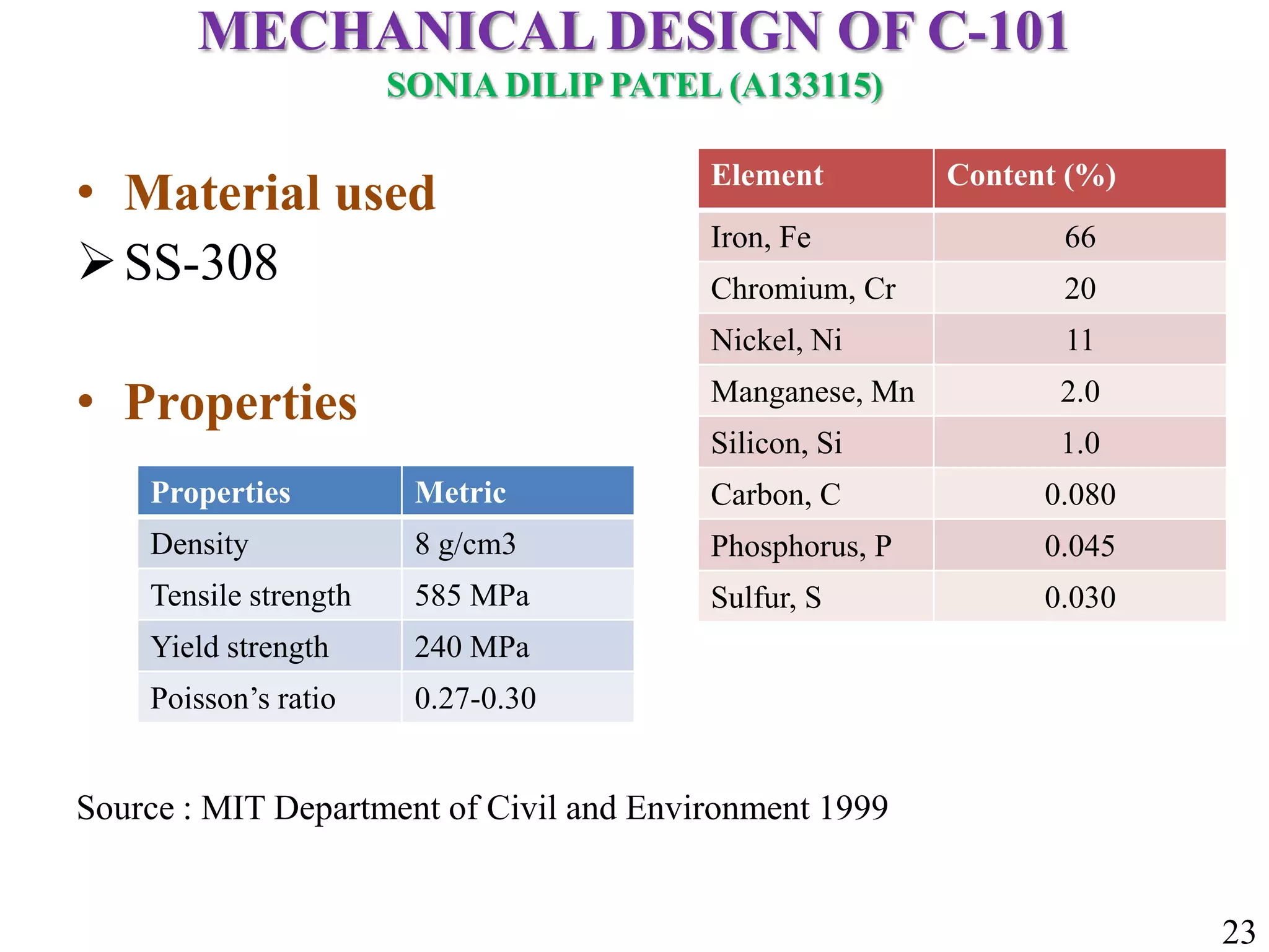
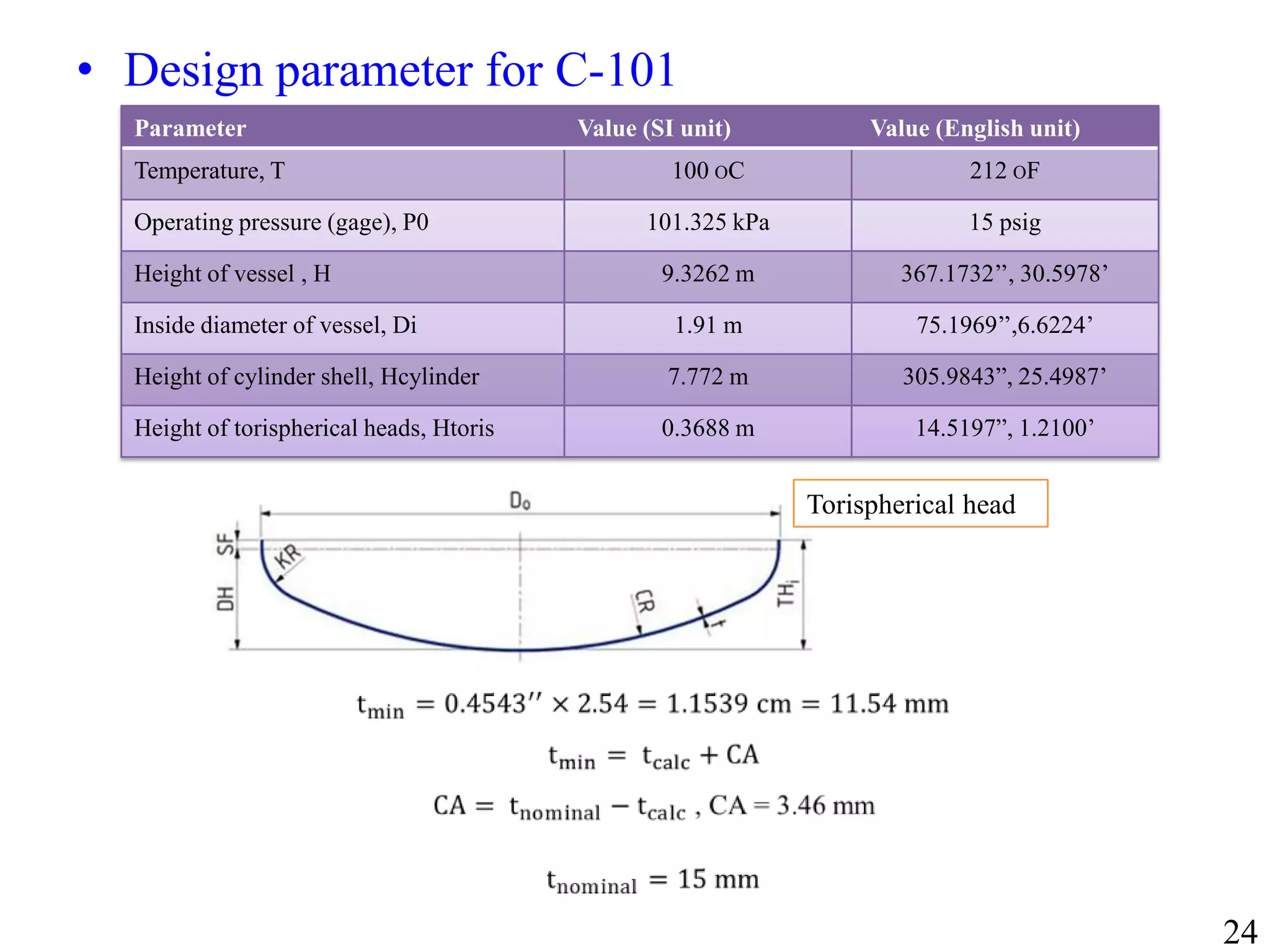
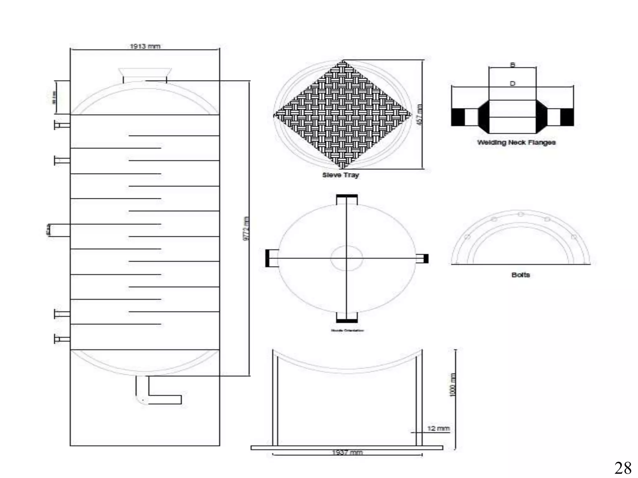
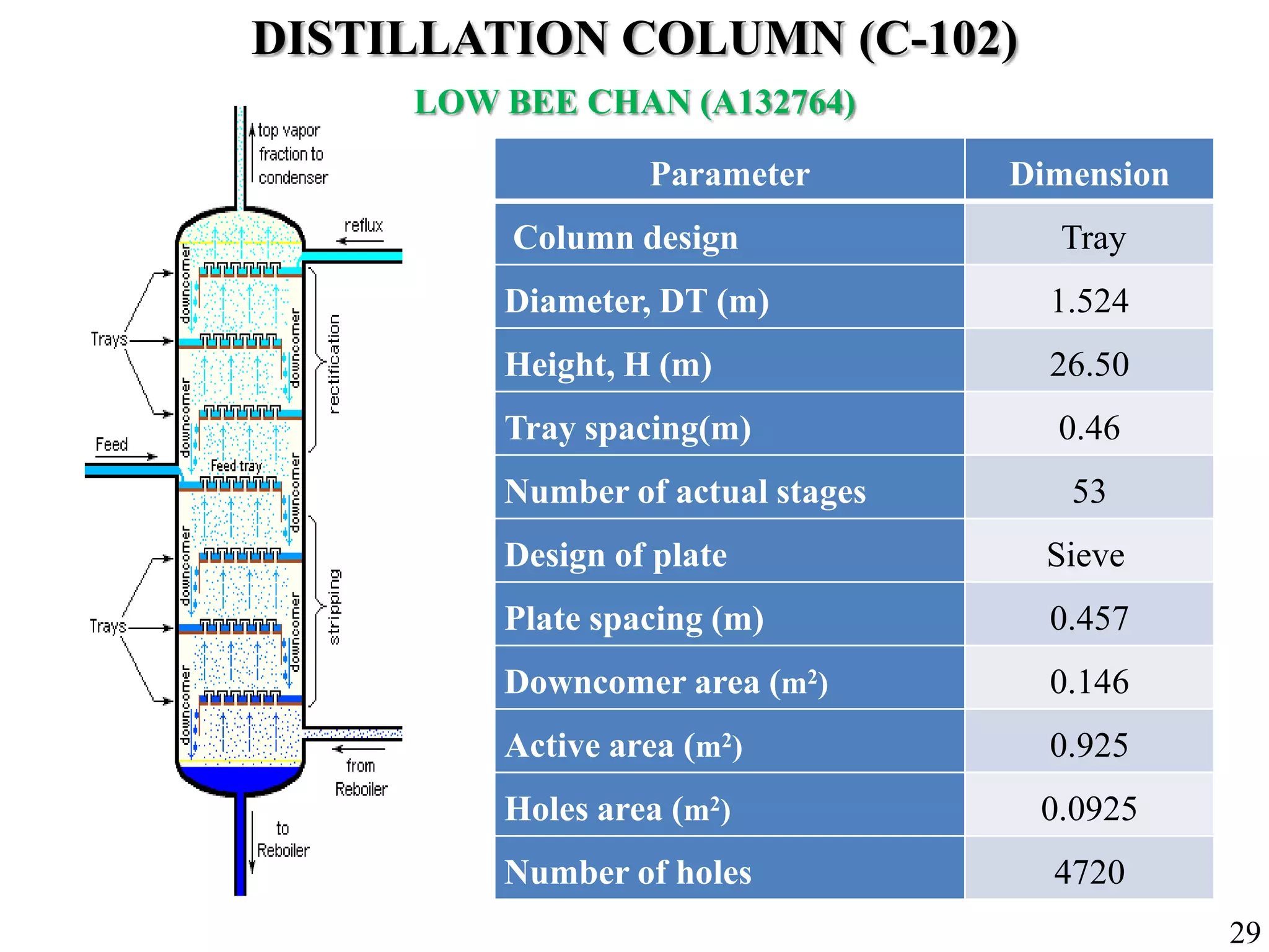
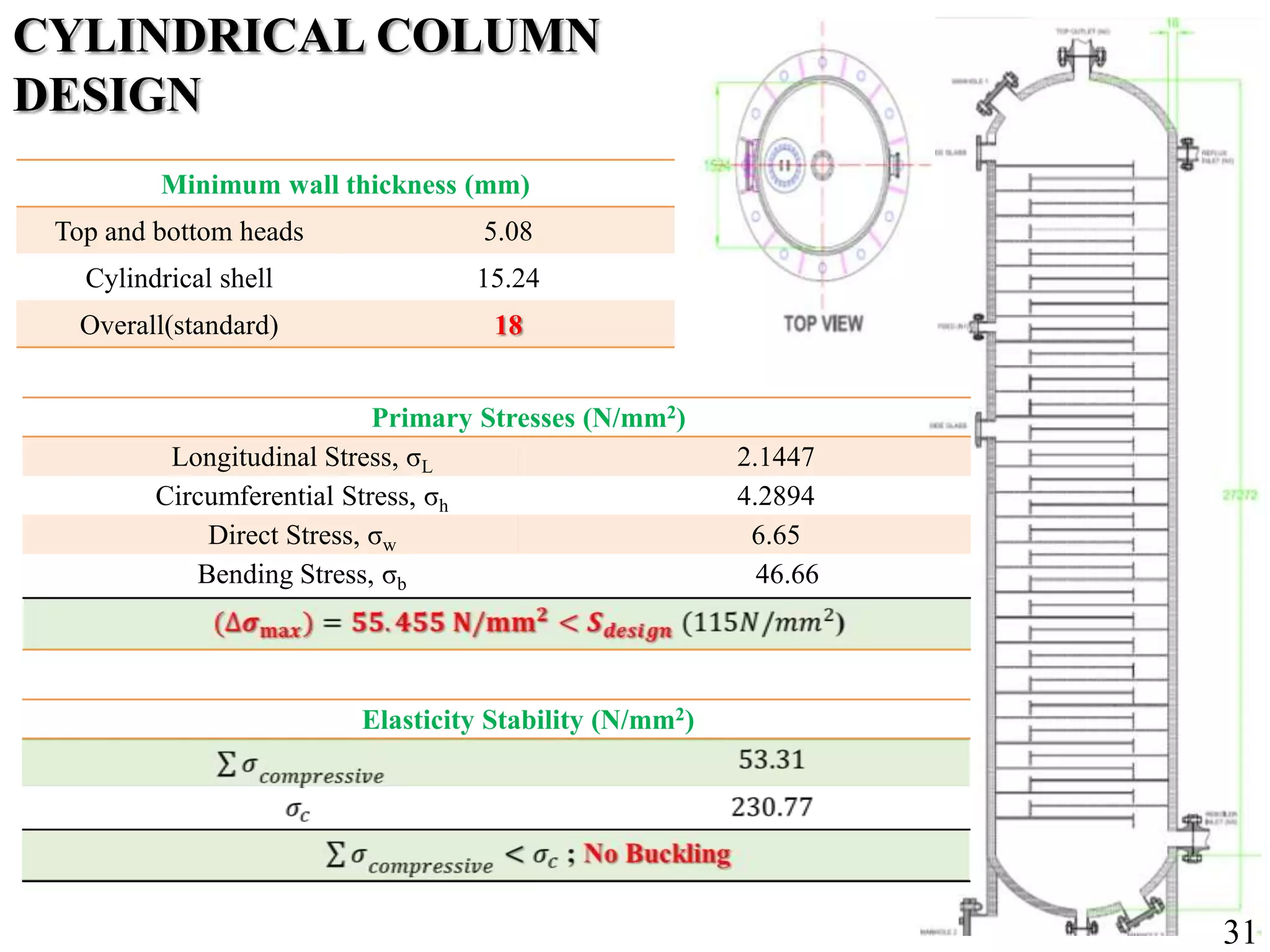
Specifications and mechanical design parameters for distillation column addressing ethanol purification.
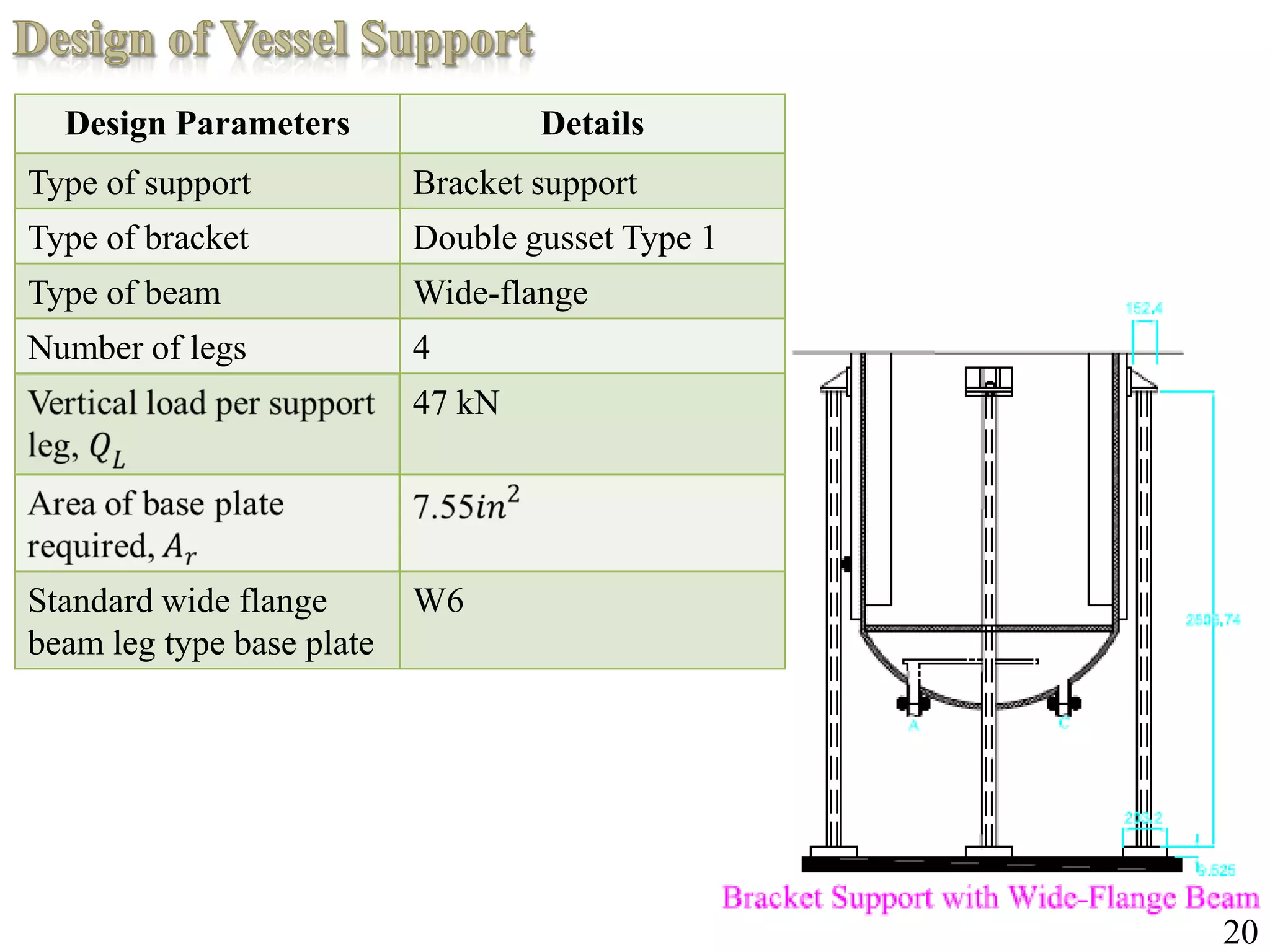
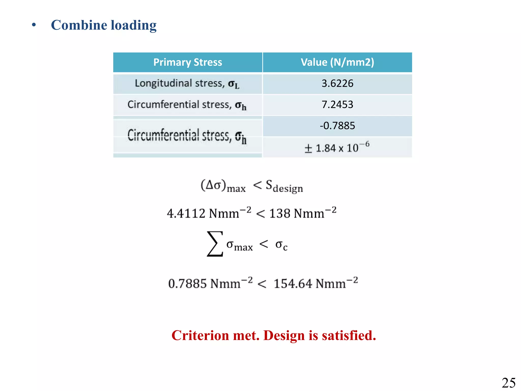
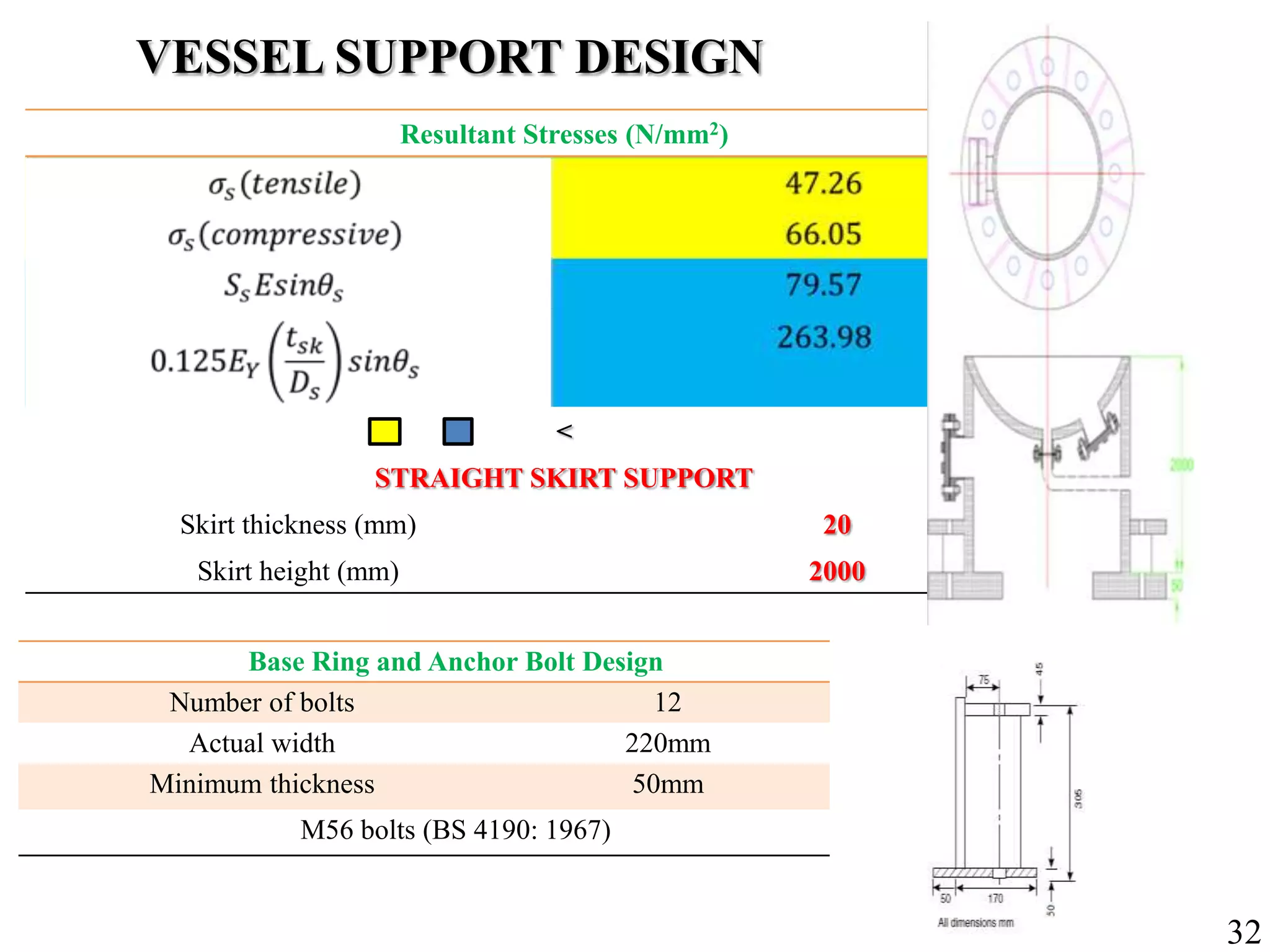
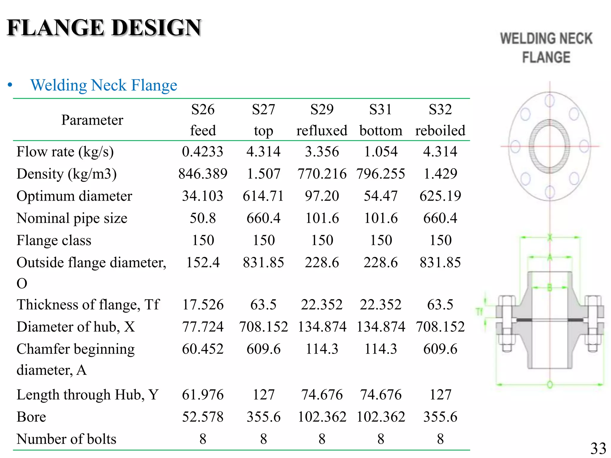
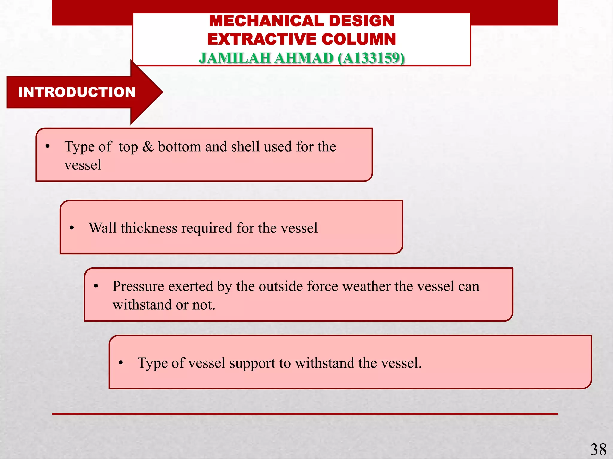
Design considerations for vessel supports and flanged joints, ensuring structural integrity.
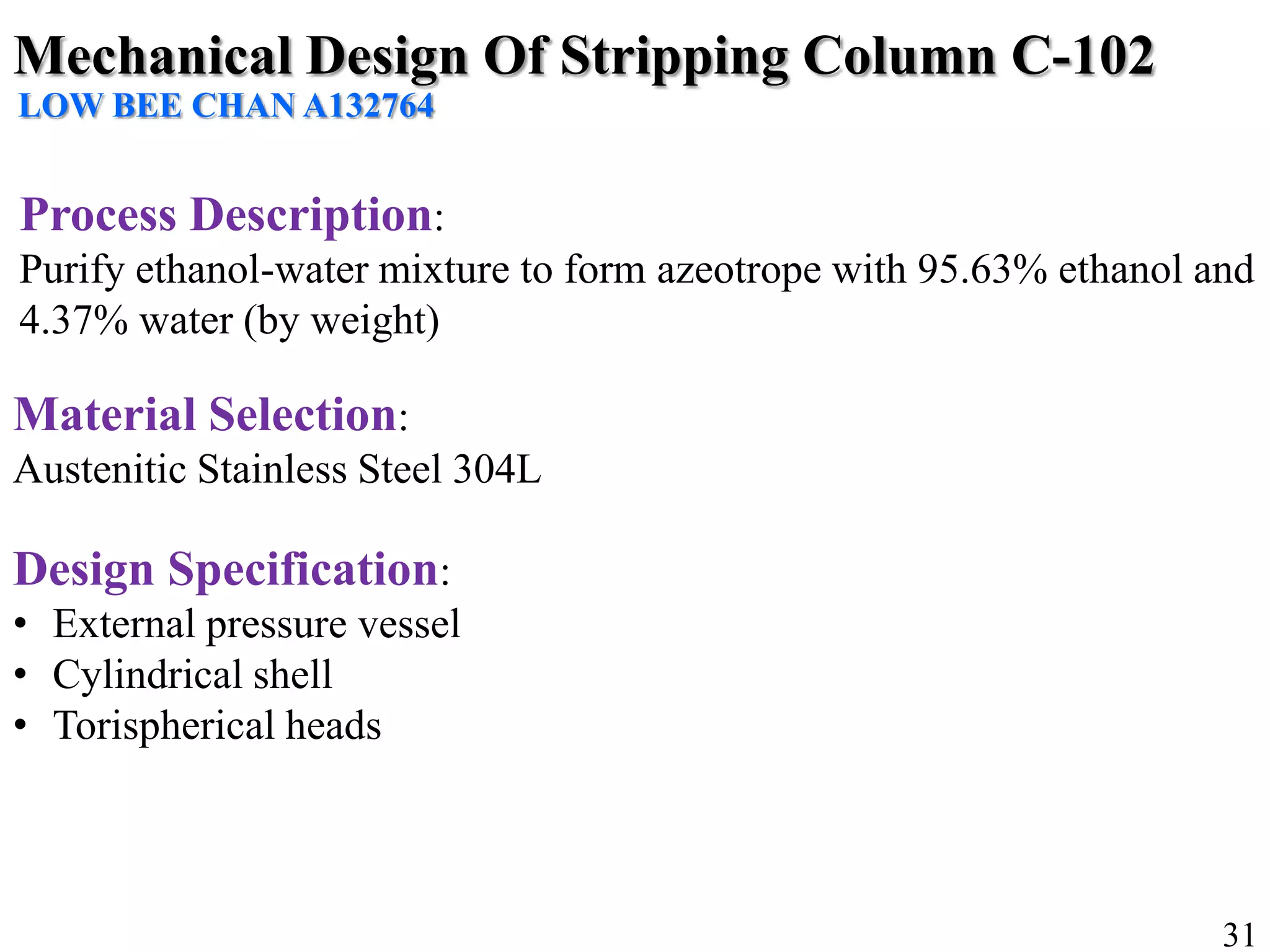
Mechanical designs and specifications for the stripping column to support ethanol-water mixtures.
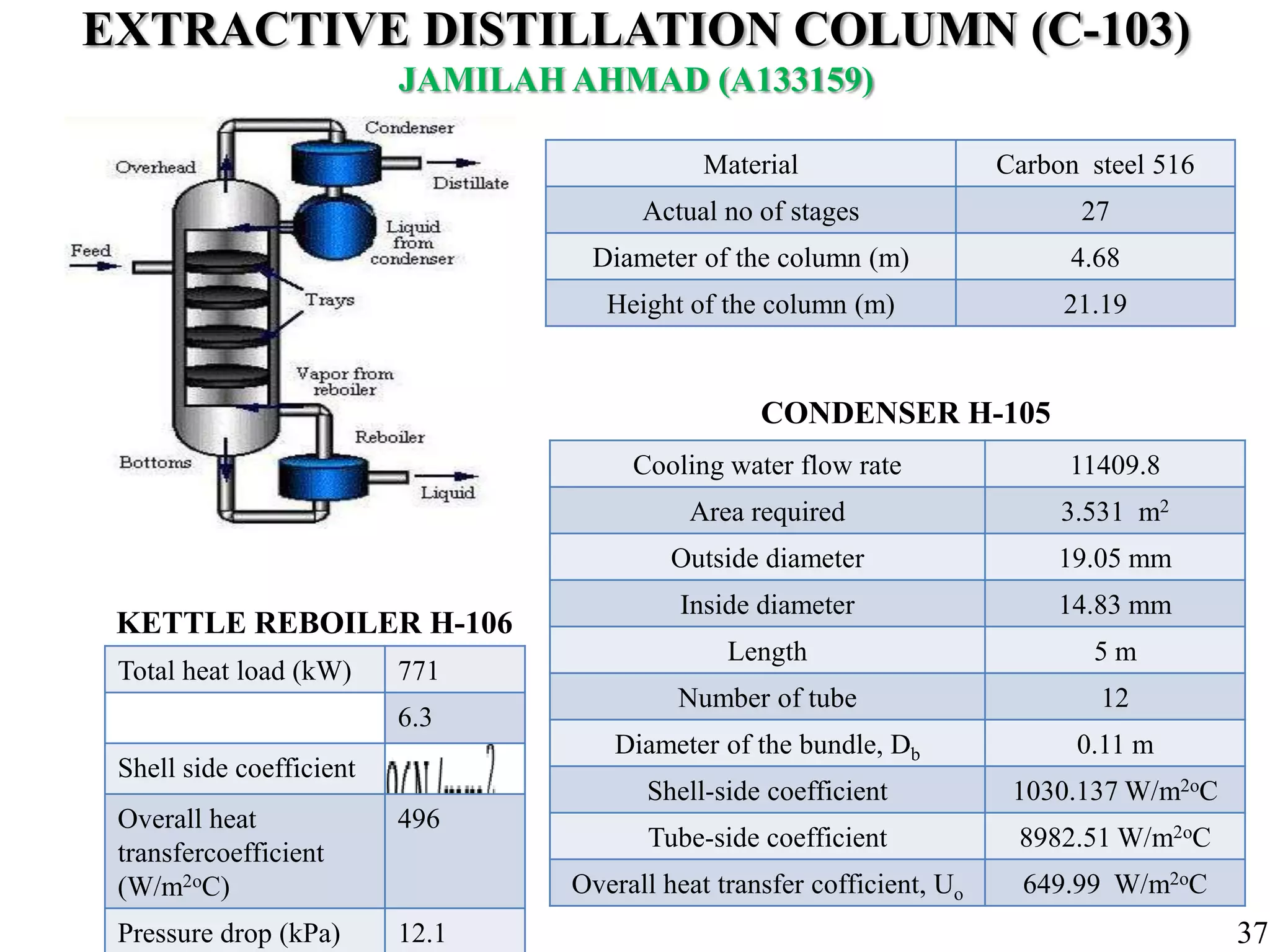
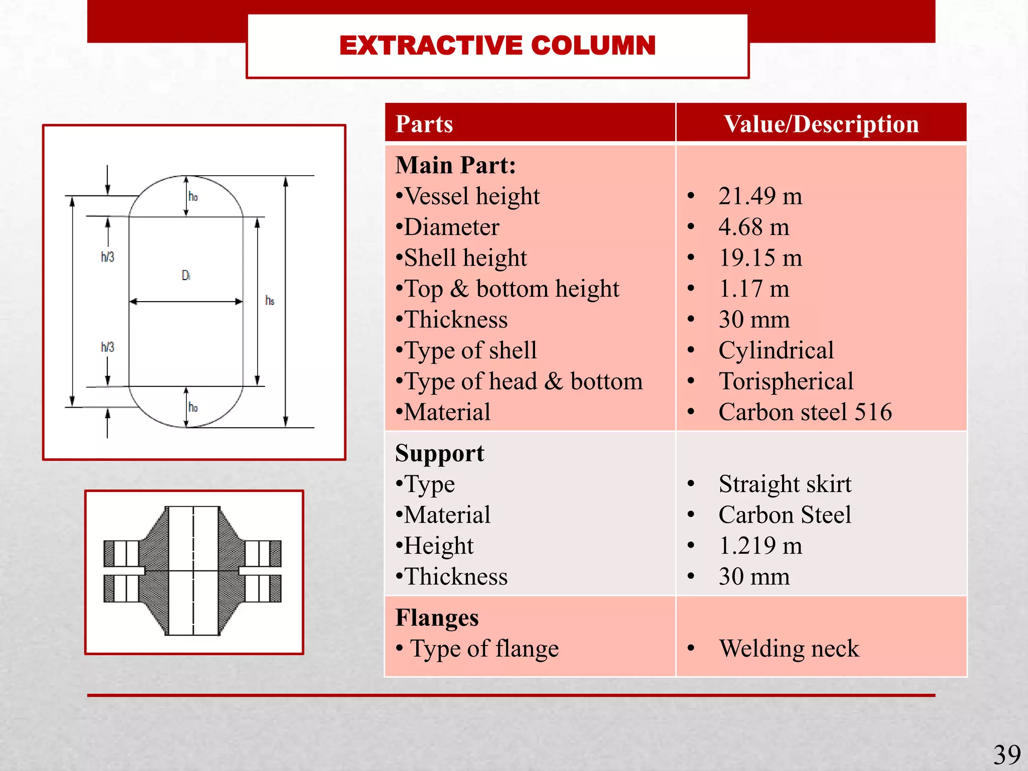
Details of the extractive column used for bioethanol separation, including dimensions and materials.
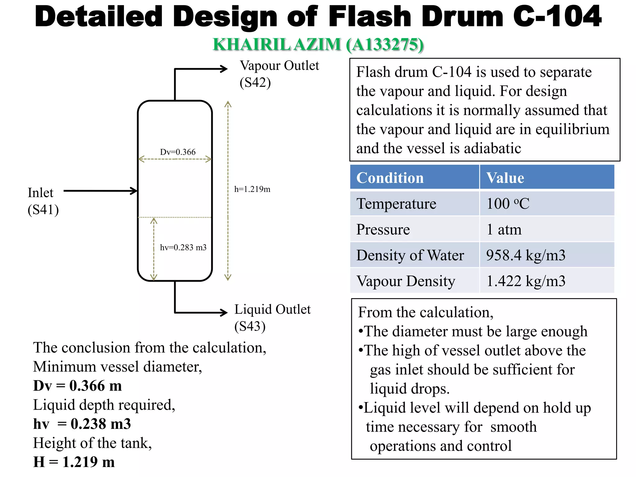
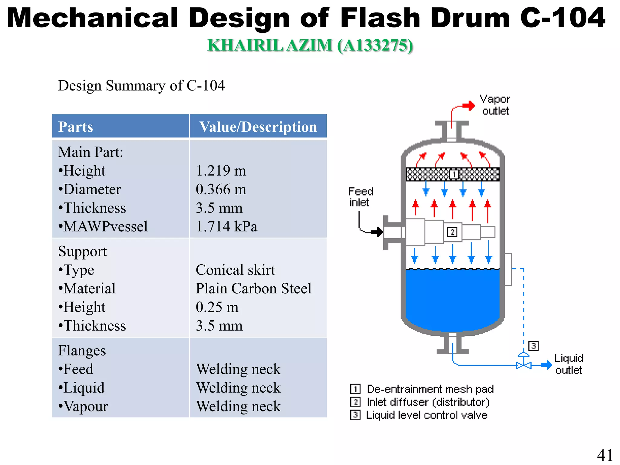
Design calculations for a flash drum, addressing separation of vapor and liquid phases.
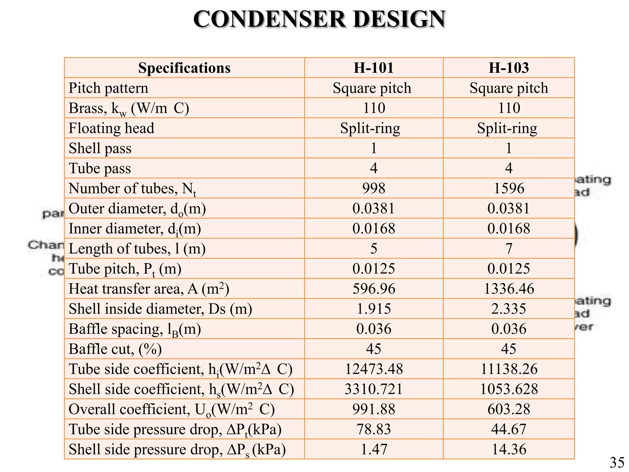
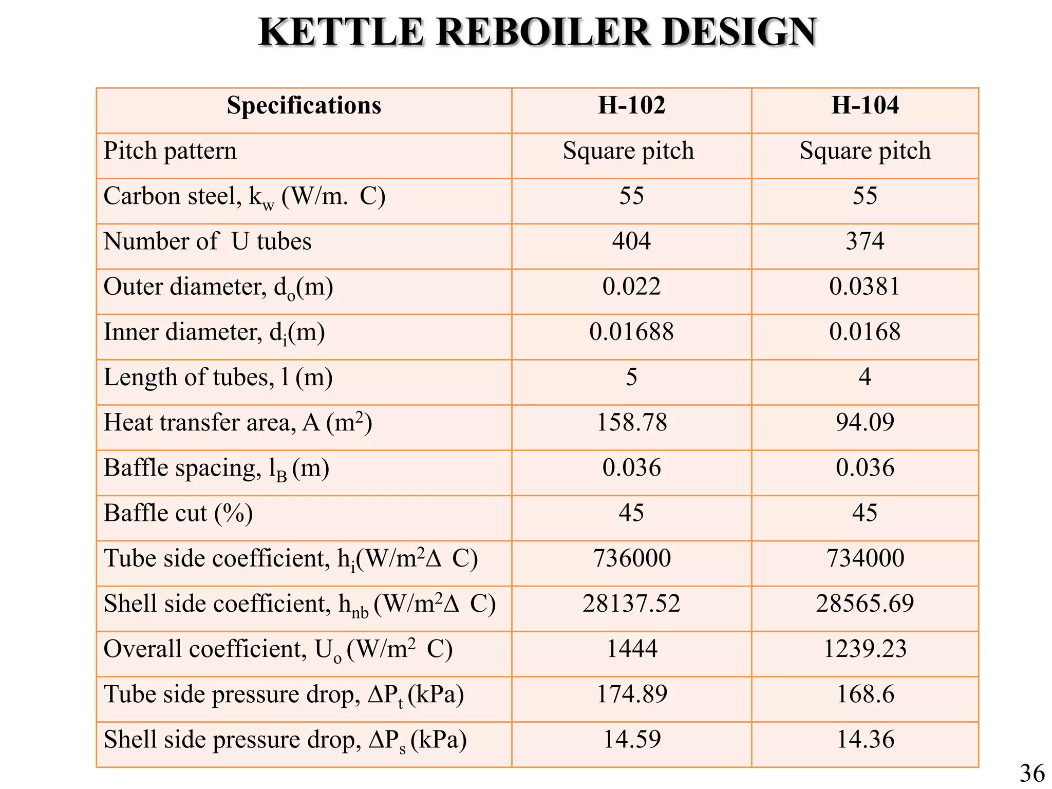
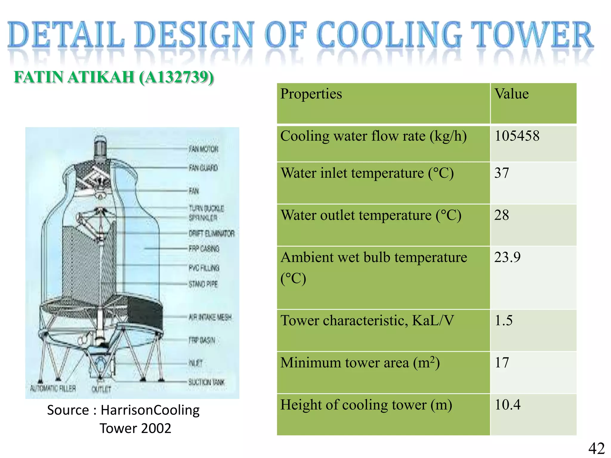
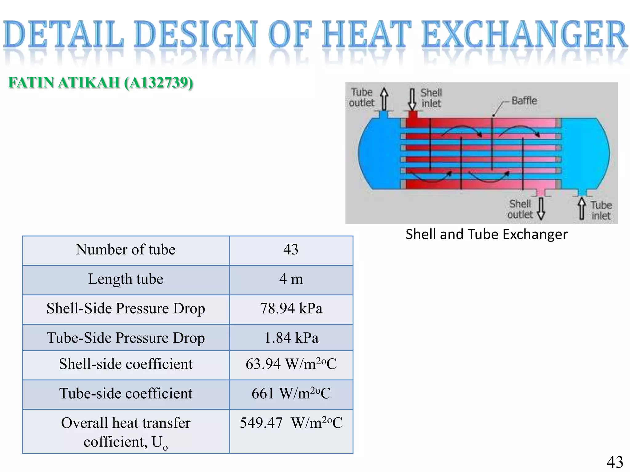
Specifications for the cooling tower and shell-and-tube heat exchangers.
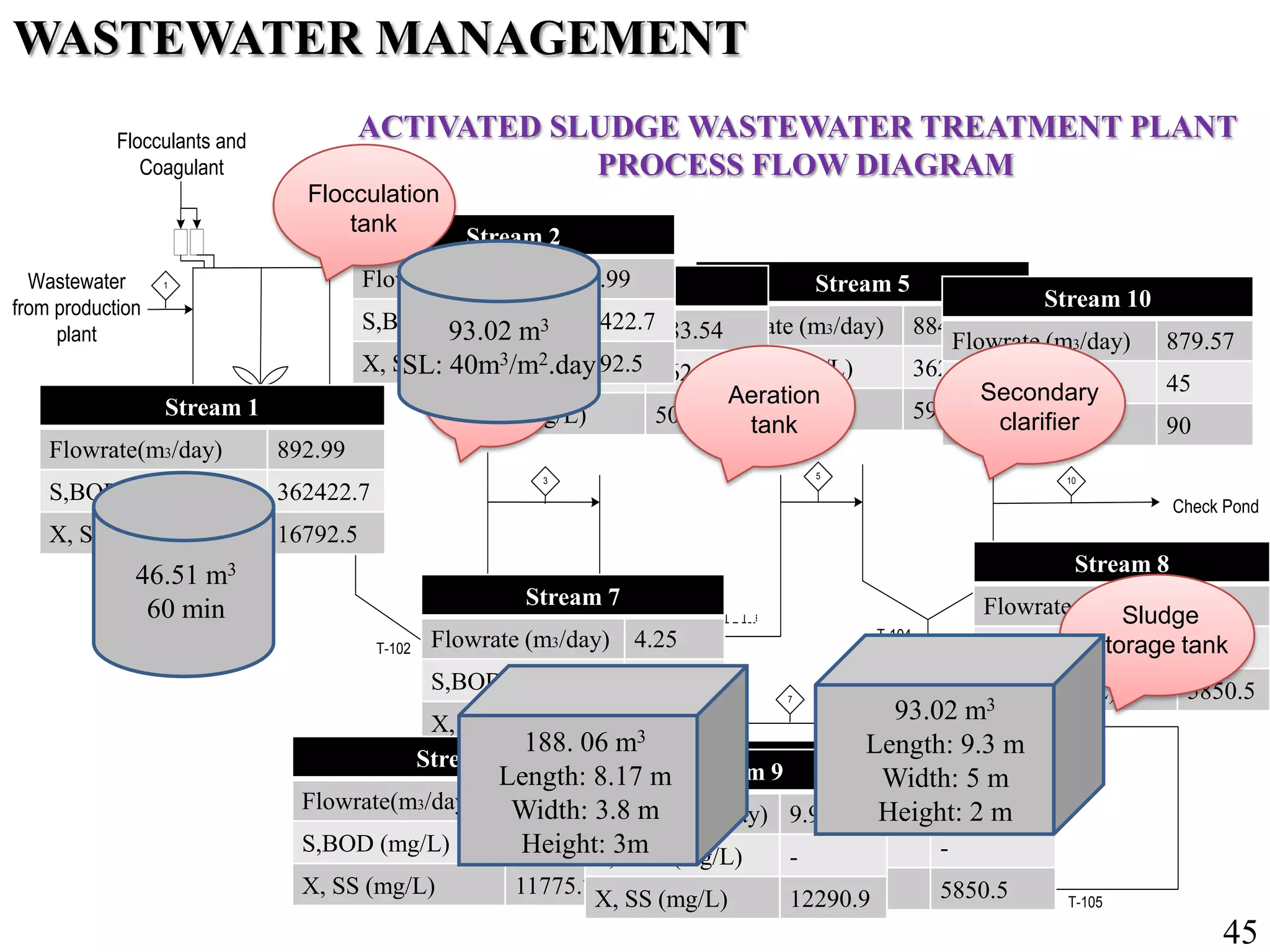
Process flow diagram for wastewater management, detailing treatment stages and pollutant reduction.
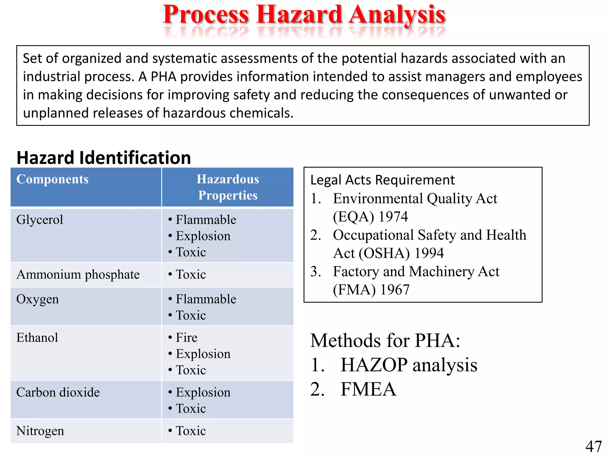
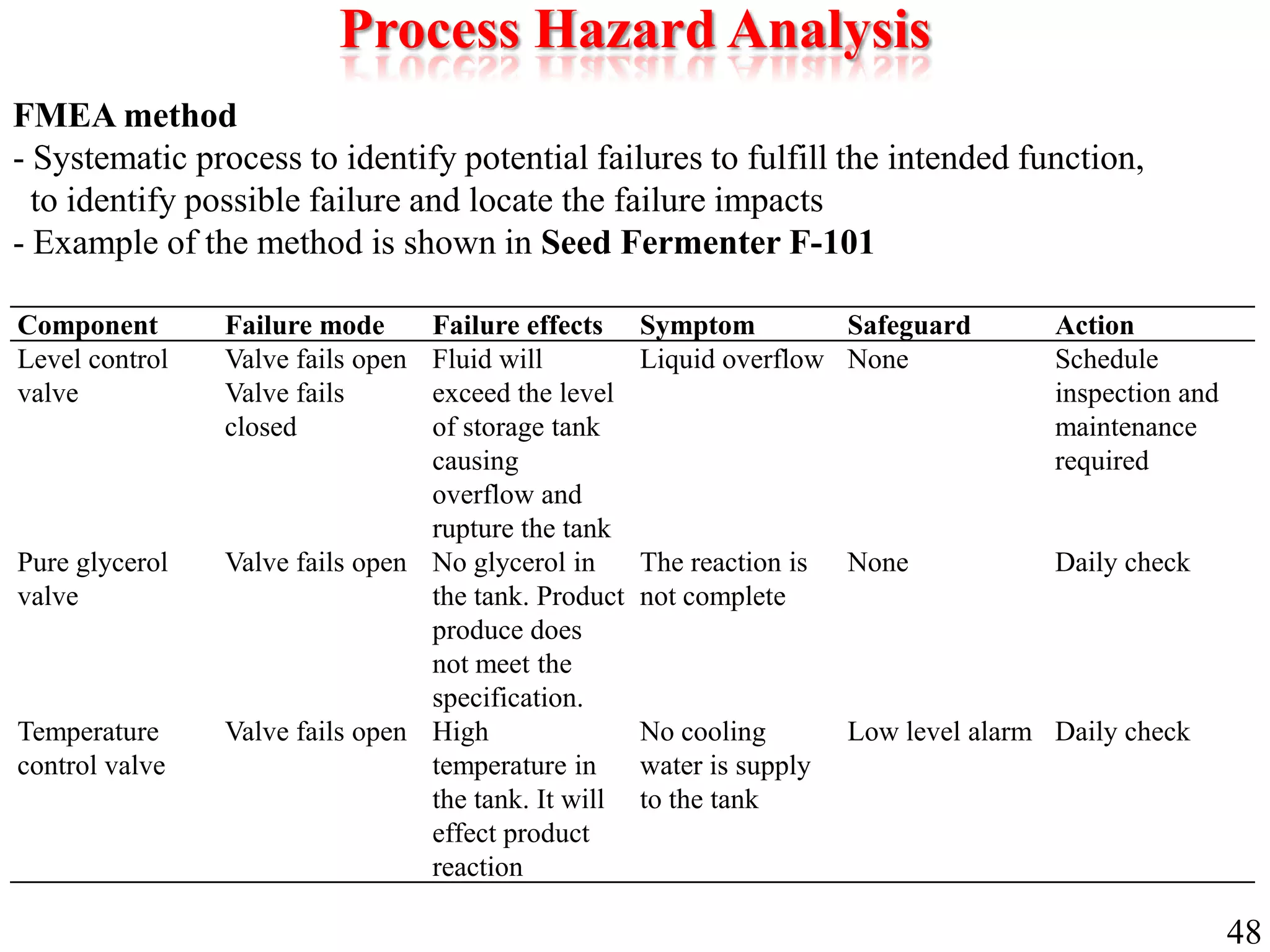
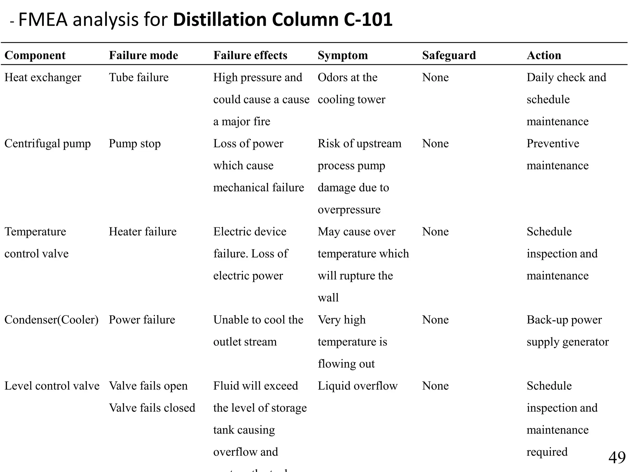
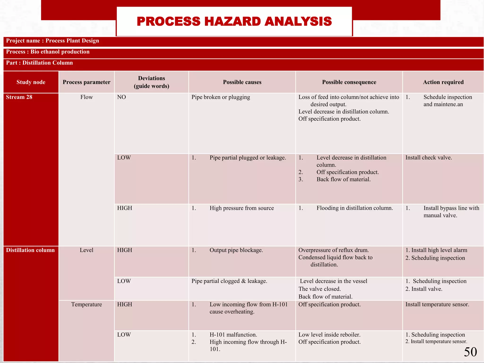
Hazard identification and analysis through HAZOP and FMEA methodologies addressing potential risks.
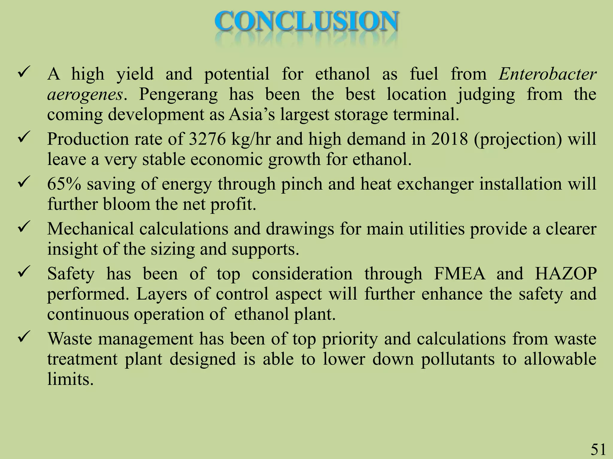
Conclusion summarizing key insights, potential for profit and safety in bioethanol production.


