Download to read offline
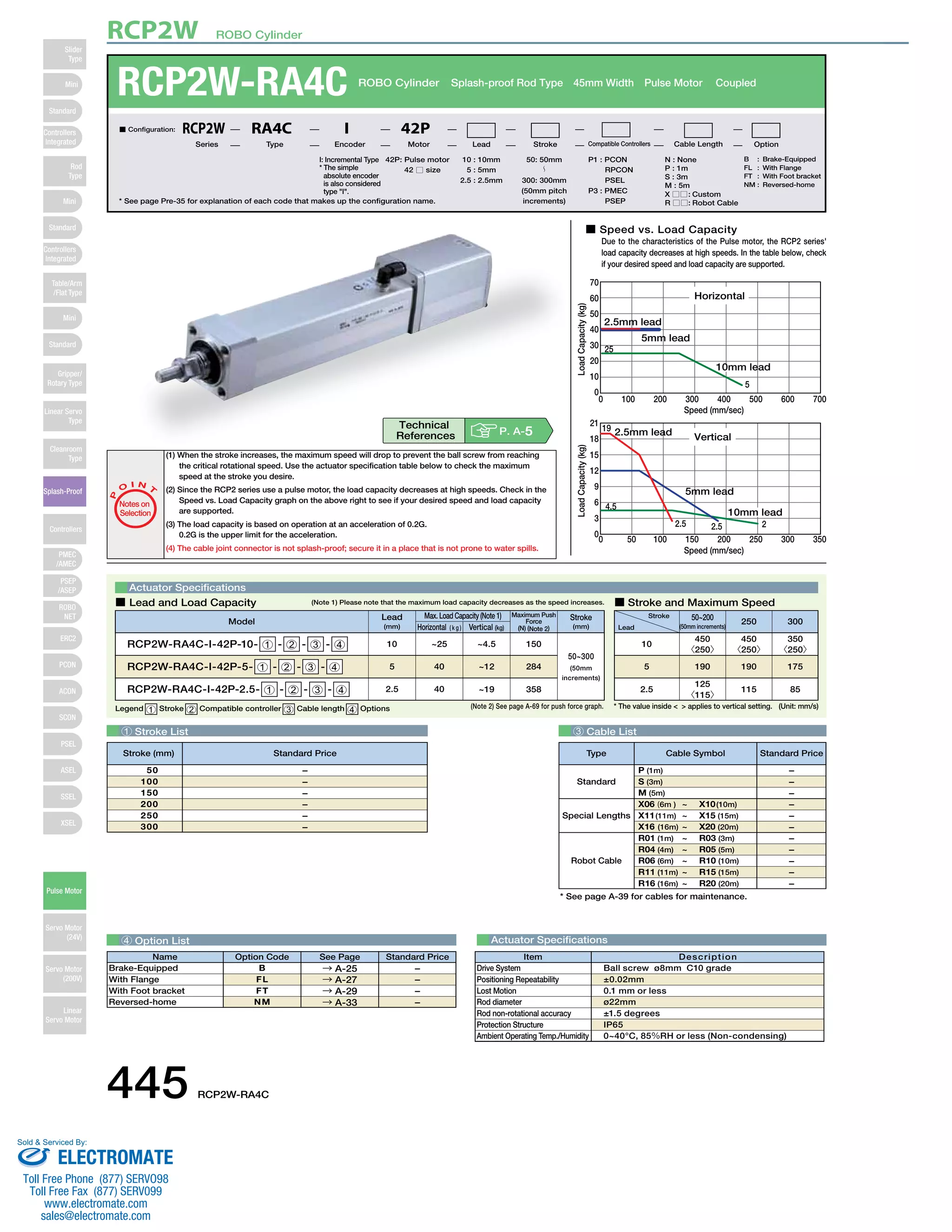
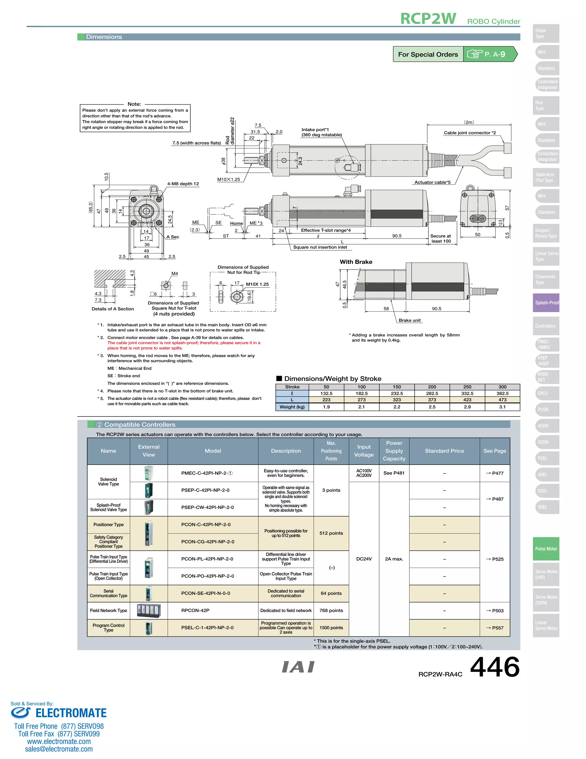

The document provides specifications for the RCP2W-RA4C ROBO Cylinder. It includes details on the actuator such as its speed and load capacity graphs, dimensions and weights by stroke, compatible controllers, and configuration name breakdown. The actuator uses a pulse motor, ball screw drive system, and has an IP65 splash-proof protection structure for use between 0-40°C and 85% humidity. It can operate with compatible mini or standard controllers from the manufacturer.


