Iai rcp4 w-ra_specsheet
•
0 likes•436 views

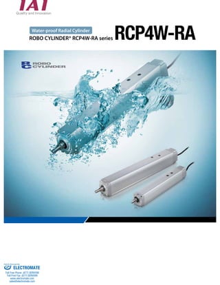
1. The document introduces the ROBO Cylinder RCP4W-RA series of water-proof radial cylinders. 2. The RCP4W model features an IP67 rating, making it protected against dust and able to be submerged in water. It has a built-in linear guide to accommodate loads up to 100mm offset from the rod center. 3. The document provides specifications for various RCP4W models including strokes from 50-500mm, speeds up to 560mm/s, payloads up to 50kg, and options like cable exits, flanges and brackets.

Recommended
More Related Content
What's hot
What's hot (19)
Viewers also liked
Viewers also liked (17)
Similar to Iai rcp4 w-ra_specsheet
Similar to Iai rcp4 w-ra_specsheet (20)
More from Electromate
More from Electromate (20)
Recently uploaded
Recently uploaded (20)
Iai rcp4 w-ra_specsheet
- 1. Water-proof Radial Cylinder RCP4W-RA ROBO CYLINDER® RCP4W-RA series Sold & Serviced By: ELECTROMATE Toll Free Phone (877) SERVO98 Toll Free Fax (877) SERV099 www.electromate.com sales@electromate.com
- 2. 1 Introducing the IP67 Water-proof Radial Cylinder– the Newest Addition to the Dust-proof/ Splash-proof ROBO Cylinder RCP4W Series Features 1 Dust-proof/Splash-proof Performance of IP67 The RCP4W rod type adopts a splash-proof structure to shut out water even when the cylinder is submerged in water, for use in food preparation machines, washing machines and other systems exposed to water splashes and jets. IP Marking IP Classes Protection against the human body and solid objects Protection against the intrusion of water IP Operate the product for 12 hours in floating talc powder (grain size: 25 μm) Submerge the product in water and kept it 1m below the water surface for 30 minutes. IP class Description Applicable IAI products IP67 Solid objects Fully protected against the entry of powder dust into the equipment. Water Even when the equipment is submerged in water, water does not enter the equipment. IP65 Solid objects Fully protected against the entry of powder dust into the equipment. Water The equipment receives no harmful effect even when directly hit by water jets from any direction. IP54 Solid objects Dust that would affect the operation of the equipment does not enter the equipment. Water The equipment receives no harmful effect even when contacted by water splashes from any direction. IP50 Solid objects Dust that would affect the operation of the equipment does not enter the equipment. Water The equipment is not protected against water. Slider type RCP2W-SA16C Slider type RCP4W Slider type ISWA/ISPWA Pulse motor rod type RCP2W-RA4C/RA6C SCARA robot IX-NNW High-thrust rod type RCP2W-RA10C 24-V servo motor rod type RCAW-RA3/RA4 200-V servo motor rod type RCS2W-RA4 Small gripper (dust-proof type) RCP2W-GR First digit Second digit In-house Test Methods Conforming to JIS C0920 In-house Test Methods against Solid Objects Results Powder did not enter the product. In-house Test Method against Water Results Water did not enter the product. NOTE: The splash-proof performance has been measured only with regard to water. Protection against coolant, cleaning solution, etc., is not guaranteed. If you wish to use your product in an environment where it may come in contact with coolant, consult IAI beforehand. Rod type RCP4W High Environmental Resistance Low Sold & Serviced By: ELECTROMATE Toll Free Phone (877) SERVO98 Toll Free Fax (877) SERV099 www.electromate.com sales@electromate.com
- 3. 2 RCP4W 2 Built-in Guide to Achieve Longer Strokes While 3 4 Accommodating a Radial Load on the Rod A ball-circulating linear guide is built into the actuator to achieve longer strokes of up to 500 mm. The guide also accommodates a load offset from the rod center (by up to 100 mm), which expands the degree of freedom in transfer applications. High Speed and High Acceleration/Deceleration The RCP4W boasts the maximum acceleration/ deceleration of 1 G and maximum speed of 560 mm/s, which are approx. 1.6 times the maximum acceleration/ deceleration and maximum speed of any conventional splash-proof rod type, enabling a shorter cycle time for your system. Improved Maintainability The ball screw and guide can be lubricated at the same time by adding grease from the grease nipples provided on the top face of the nut holder. Another grease nipple is provided on the top face of the front bracket to grease the sliding part of the rod. Replacing the seals at the sliding part of the rod is very easy, because all you need is to change the front bracket. New type RCP4W-RA6C RCP2W-RA6C Approx. 1.6 times faster Conventional splash-proof rod type Front bracket Grease nipple Sold & Serviced By: ELECTROMATE Toll Free Phone (877) SERVO98 Toll Free Fax (877) SERV099 www.electromate.com sales@electromate.com
- 4. 3 Specification Table Type External view Actuator size (mm) Stroke Model Number (mm) Ball screw lead (mm) Maximum speed (mm/s) (*1) Payload (kg) Maximum Push Force (N) Reference page Horizontal Vertical RA6C 50~400 (Every 50) 12 560 <500> 20 3 93 6 360 40 8 185 P5 3 180 50 16 370 70 - 30 590 RA7C 50~500 (Every 50) 16 560 <400> 40 7 219 P7 8 340 <280> 50 15 437 4 170 <140> 70 25 875 80 - 45 1030 (*1) The values in < > apply when the actuator is used vertically. Actuator RCP4W Series Type code Encoder type Motor type Ball screw lead Stroke (mm) Applicable controller Cable length Options P3 PCON-CA P4 PCON-CFA N No cable P N 1 m S 3 m M 5 m RA6C Actuator width 65mm RA7C Actuator width 75mm I Incremental 3 Lead 3 ~ ~ X NOTE: The settings for motor type, ball screw lead, stroke and options vary from one model to another. For details, check the specifications for each model. 42P 42 motor 42SP 42 high-thrust motor 56P 56 motor 56SP 56 high-thrust motor 4 Lead 4 6 Lead 6 8 Lead 8 12 Lead 12 16 Lead 16 50 50mm 500 500mm (Can be set in 50-mm increments.) Specified length R Robot cable A1 Cable exit from the left A3 Cable exit from the right AT Cable exit from the top B Brake FL With flange FT With foot bracket NM Non-motor side specification Sold & Serviced By: ELECTROMATE Toll Free Phone (877) SERVO98 Toll Free Fax (877) SERV099 www.electromate.com sales@electromate.com
- 5. 4 RCP4W Options Optional Cable Exit Direction Code: A1, A3, AT You can select one of the following three cable exit directions. If no direction is specified, the cable exits from the rear. *In the following figures, ( ) and < > refer to RA6 and RA7, respectively. Other than that, it refers to a common dimension. Exit from the rear (standard) Option code: (Blank) Exit from the left side face Option code: A1 Exit from the right side face Option code: A3 Exit from the top side face Option code: AT Brake Option code: B This option is provided to prevent the rod from dropping upon cutoff of power when the actuator is used vertically. Non-motor side Specification Option code: NM Normally the home position is where the rod is retracted. This option is provided to define the condition where the rod has extended as home. With Flange Option code: FL This flange is used to secure the actuator with bolts from the actuator side. 4-6.6, bored through RCP4W-RA6 type RCP4W-RA7 type Model number of flange: RCP4W-FL-RA6 4-9, bored through Model number of flange: RCP4W-FL-RA7 Option code: FT With Foot Bracket This bracket is used to secure the actuator with bolts from above. 4-ø8.6, drilled RCP4W-RA6 type Model number of bracket: RCP4W-FT-RA6 RCP4W-RA7 type Model number of bracket: RCP4W-FT-RA7 Spare Parts As a rough guide, replace the scraper (front bracket assembly) after every 1,000 km of traveling or 1 year of use. When replacing the scraper, specify the applicable model number in your order as shown below. No Name Model Number Order unit RA6 RA7 1 Front bracket assembly RCP4W-FBA-RA6 RCP4W-FBA-RA7 1 2 O-ring RCP4W-OR1-RA6 RCP4W-OR1-RA7 1 3 O-ring RCP4W-OR2-RA6 RCP4W-OR2-RA7 1 4 Cap RCP4W-CS-RA 1 5 Bolt (Supplied with the front bracket assembly) 4-ø6.6 drilled Sold & Serviced By: ELECTROMATE Toll Free Phone (877) SERVO98 Toll Free Fax (877) SERV099 www.electromate.com sales@electromate.com
- 6. 5 ROBO Cylinder Water-proof rod type Actuator width: 65 mm 24-V Pulse motor Correlation Diagrams of Speed and Payload Due to its pulse motor characteristics, the RCP4 series provides lower payload at higher speed. Check the tables below to see if the desired speed and payload can be achieved. RCP4W-RA6C Horizontal (Normal condition of use) Lead 3 (standard specication) 60 50 40 30 20 LLeeaadd 66 Horizontal LLeeaadd 1122 LLeeaadd 1122 Speed (mm/s) RCP4W-RA6C Vertical (Normal condition of use) Lead 3 (standard specication) 16 16 Speed (mm/s) 60 50 40 30 20 10 35 30 25 20 15 10 0 Horizontal 10 7 7 Speed (mm/s) 35 30 25 Vertical Vertical 0 100 200 300 400 500 600 The values below are based on operation at 0.3 G. 25 Lead 3 (standard specication) The values below are based on operation at 0.3 G. The values below are based on operation at 0.5 G. The values below are based on operation at 0.5 G. Lead 3 (standard specication) LLeeaadd 66 25 20 15 10 8 8 3 5 4 3 5 4 11 11 0 0 100 200 300 400 500 600 RCP4W-RA6C Horizontal (Environmental temperature of 5°C or below) RCP4W-RA6C Vertical (Environmental temperature of 5°C or below) 0 0 100 200 300 400 500 600 Speed (mm/s) 5 0 0 100 200 300 400 500 600 5 Payload (kg) Payload (kg) Payload (kg) Payload (kg) Lead 3 (High-thrust specication) Lead 3 (High-thrust specication) LLeeaadd 66 LLeeaadd 66 LLeeaadd 1122 LLeeaadd 1122 2 2 RCP4W-RA6C Notes on selection 42P: Pulse motor, (1) The maximum payload is the value when operated horizontally and vertically at 0.3G and 0.5G, respectively. Note that raising the acceleration causes the payload to drop. (Refer to P. 10 for the maximum payload by acceleration.) (2) The horizontal payload is calculated by assuming that an external guide is also used. (3) The high-thrust specification is designed exclusively for vertical operation. It comes standard with a brake. size 42 42SP: High-thrust pulse motor, size 42 I: Incremental specification P3: PCON-CA Refer to the option list below. 50 : 50mm 400 : 400mm (every 50-mm) * If the high-thrust pulse motor is selected, the actuator comes standard with option B (Brake). 12 : 12mm 6 : 6mm 3 : 3mm RA6C Type I Encoder type Motor type P3 Applicable Lead Stroke controller Cable length Options RCP4W Series Model Specification Items ~ N: None P: 1m S: 3m M: 5m X : Specified length R : Robot cable Built-in Guide Mechanism Actuator Specifications (unit: mm/s) Actuator Specifications Leads and Payloads Stroke and Maximum Speed Model number Lead (mm) Maximum payload (kg) Maximum push force (N) Positioning repeatability (mm) Stroke Horizontal Vertical (mm) (kg) (kg) Standard specification RCP4W-RA6C-I-42P-12- 1 -P3- 2 - 3 12 20 3 93 ±0.02 50 to 400 (in 50-mm increments) RCP4W-RA6C-I-42P-6- 1 -P3- 2 - 3 6 40 8 185 RCP4W-RA6C-I-42P-3- 1 -P3- 2 - 3 3 50 16 370 High-thrust specification RCP4W-RA6C-I-42SP-3- 1 -P3- 2 - 3 -B 3 – 30 590 Stroke (mm) Standard price Standard specification High-thrust specification 50 – – 100 – 150 – 200 – 250 – 300 – 350 – 400 – Stroke Item Description Drive system Ball screw ø10mm, rolled C10 Positioning repeatability ±0.02mm Lost motion 0.1mm or less Rod ø22 stainless steel pipe Rod non-rotation accuracy ±0.1 deg Allowable load/allowable torque at end of rod Refer to the page on the right. Lost offset distance at end of rod 100mm or less Protective structure IP67 Ambient operating temperature, humidity 0 to 40°C, 85% RH or less (Non-condensing) Legend 1 Stroke 2 Cable length 3 Options Type Cable symbol Standard price Standard type P (1m) – S (3m) – M (5m) – Special length X06 (6m) ~ X10 (10m) – X11 (11m) ~ X15 (15m) – X16 (16m) ~ X20 (20m) – Robot cable R01 (1m) ~ R03 (3m) – R04 (4m) ~ R05 (5m) – R06 (6m) ~ R10 (10m) – R11 (11m) ~ R15 (15m) – R16 (16m) ~ R20 (20m) – 1 Stroke 2 Cable length 50 (mm) 100 ~ 400 (in 50-mm increments) 12 500 [450 400] 560 500 [450 400] 6 360 [300] 3 180 [150] 3 70 [70] Lead *The values in apply when the actuator is used vertically. *The values in [ ] apply when the actuator is used at an environmental temperature of 5°C or below. 1 Options Name Option code See page Standard price Cable exit from the left side face A1 P4 – Cable exit from the right side face A3 – Cable exit from the top face AT – Brake B – With flange FL – With foot bracket FT – Non-motor side specification NM – *The high-thrust specification comes standard with a brake. Offset distance at end of rod (100mm or less) Load at end of rod Sold Serviced By: ELECTROMATE Toll Free Phone (877) SERVO98 Toll Free Fax (877) SERV099 www.electromate.com sales@electromate.com
- 7. 6 Exit from the left side face Exit from the right side face 17 14 68.5 40 14 65 X 8 0.5 4.3 7.3 1.5 4 Cable Exit Direction Option Exit from the top Standard specication: 3 (Outer diameter of connection hose: ø6) High-thrust specication: 2 Y 50 40 C B×100P A ME SE ME*2 (T-slot distance) 42 26 +0.012 0 5 Detail Y M10×1.25 6 (19.6) 23 47 45.5 Stroke 17 31 22 4 M10×1.25 L (2m) 4-M6, depth 9 46 Reference plane Detail view of X at 1:1 (Reference plane and T-slot) Standard specication: 3 High-thrust specication: 2 4 30 D-M4, depth 6 2-ø4H7, depth 6.5 (from the bottom of the base) Intake/discharge port Oblong hole, depth 6.5 (from the bottom of the base) Supplied rod end nut Secure 100 or more Front housing *4 M (Reference plane, eective T-slot range) Cable joint connector *1 7.5 (Width across ats) *3 øl41 h7 Outer diameter of rod: ø22 Home Dimensional Drawings *1 Connect the motor and encoder cables. *2 The rod moves to the ME during home return, so pay attention to possible contact with surrounding structures and objects. *3 The orientation of the width across flats varies from one product to another. *4 When installing the actuator using the front housing or flange, make sure the actuator does not receive any external force Materials of Key Components Frame Aluminum extrusion material (A6063SS-T5 or equivalent) with white alumite coating Front bracket Aluminum die-cast Rear cover Aluminum die-cast Rod Stainless steel pipe (SUS304 or equivalent), polished + hard chrome plated Actuator cable Polyvinyl chloride (PVC) Intake/exhaust port Polyphenylene sulfide (PPS) 1 2 3 4 5 6 AT Option code: AT Option code: A1 22.5 13.5 (47) (20.5) 22.5 13.5 (47) Option code: A3 (20.5) 13.5 22.5 (47) ■ Dimensions and Mass by Stroke 2.0 1.8 1.6 1.4 1.2 1.0 0.8 0.6 0.4 0.2 0.0 0 10 20 30 40 50 Deection (mm) Load at end of rod (N) Home ■ Rod Deflection of RCP4W-RA6C (Reference Values) (The graph below plots deflection as measured by installing the actuator vertically and applying a force to the rod from one side.) Stroke 50 100 150 200 250 300 350 400 L Without brake 285 335 385 435 485 535 585 635 With brake (*) 346 396 446 496 546 596 646 696 A Without brake 40 40 40 40 40 40 40 40 With brake (*) 101 101 101 101 101 101 101 101 B 1 1 2 2 3 3 4 4 C 35 85 35 85 35 85 35 85 D 6 6 8 8 10 10 12 12 M Without brake 215 265 315 365 415 465 515 565 With brake 276 326 376 426 476 526 576 626 Allowable static load at end of rod (N) 65.6 51.2 41.7 34.9 29.8 25.7 22.4 19.7 Allowable dynamic load at end of rod (N) Load offset 0 mm 32.4 23.6 18.1 14.4 11.6 9.5 7.7 6.2 Load offset 100 mm 25.6 19.7 15.7 12.7 10.4 8.6 7.1 5.7 Allowable static torque at end of rod (N•m) 6.6 5.2 4.3 3.7 3.2 2.8 2.6 2.3 Allowable dynamic torque at end of rod (N•m) 2.6 2.0 1.6 1.3 1.0 0.9 0.7 0.6 Mass (kg) Without brake 3.1 3.5 3.8 4.2 4.6 5.0 5.4 5.8 With brake 3.6 4.0 4.4 4.8 5.2 5.6 6.0 6.4 (*) The dimensions of the high-thrust specification include the brake. Applicable Controller RCP4 series actuators can be operated with the controller indicated below. Select the type according to your intended application. view Model number Features Maximum number of Name External positioning points Input Power Power supply capacity Standard price Reference page Positioner type PCON-CA-42PI-NP--0- PCON-CA-42PI-PN--0- Positioner type based on PIO control 512 points DC24V Refer to P. 13 – Pulse-train type PCON-CA-42PI-PLN--0- Refer to P. 12 PCON-CA-42PI-PLP--0- Pulse-train input type The actuator can be operated freely by pulse-train control. – – Field network type PCON-CA-42PI--0-0- Supporting 7 major field networks 768 points – *In the model numbers shown above, indicates the field network specification (DV, CC, PR, CN, ML, EC or EP). Sold Serviced By: ELECTROMATE Toll Free Phone (877) SERVO98 Toll Free Fax (877) SERV099 www.electromate.com sales@electromate.com
- 8. 7 RCP4W-RA7C RCP4W Series Model Specification Items Built-in Guide Mechanism ROBO Cylinder Water-proof rod type Actuator width: 75 mm 24-V Pulse motor Encoder type Motor type Applicable Lead Stroke controller Cable length Options P3:PCON-CA P4:PCON-CFA *The PCON-CFA is designed exclusively for the high-thrust specification. 50 : 50mm 500 : 500mm (every 50-mm) N: None P: 1 m S: 3 m M: 5 m X : Specified length R : Robot cable ~ Lead 8 Lead 8 Lead 16 Speed (mm/s) 80 70 60 50 40 30 20 10 50 45 40 35 30 25 20 15 10 5 0 Lead 4 (High-thrust specication) Lead 4 (standard specication) Lead 4 (standard specication) Lead 4 (High-thrust specication) Lead 8 Lead 8 8 8 Lead 16 0 100 200 300 400 500 600 0 0 100 200 300 400 500 600 80 70 60 50 40 30 20 10 0 Refer to the option list below. *If the high-thrust pulse motor is selected, the actuator comes standard with option B (Brake). The values below are based on operation at 0.3 G. Horizontal Lead 16 0 100 200 300 400 500 600 50 45 40 35 30 25 20 15 10 5 0 Speed (mm/s) Lead 4 (standard specication) Lead 16 0 100 200 300 400 500 600 RCP4W-RA7C Horizontal (Normal condition of use) RCP4W-RA7C Vertical (Normal condition of use) RCP4W-RA7C Horizontal (Environmental temperature of 5°C or below) RCP4W-RA7C Vertical (Environmental temperature of 5°C or below) Horizontal Vertical Vertical Lead 4 (standard specication) The values below are based on operation at 0.3 G. The values below are based on operation at 0.5 G. The values below are based on operation at 0.5 G. 3 7 7 2 1 2 1 3 16 : 16mm 8 : 8mm 4 : 4mm Payload (kg) Payload (kg) Payload (kg) Payload (kg) Speed (mm/s) Speed (mm/s) Notes on selection 56P: Pulse motor, 56SP: High-thrust I I: Incremental specification RA7C Type (1) The maximum payload is the value when operated size 56 pulse motor, size 56 horizontally and vertically at 0.3G and 0.5G, respectively. Note that raising the acceleration causes the payload to drop. (Refer to P. 10 for the maximum payload by acceleration.) (2) The horizontal payload is calculated by assuming that an external guide is also used. (3) The high-thrust specification is designed exclusively for vertical operation. It comes standard with a brake. Correlation Diagrams of Speed and Payload Due to its pulse motor characteristics, the RCP4 series provides lower payload at higher speed. Check the tables below to see if the desired speed and payload can be achieved. 2 Cable length Type Cable symbol Standard price Standard type P (1m) – S (3m) – M (5m) – Special length X06 (6m) ~ X10 (10m) – X11 (11m) ~ X15 (15m) – X16 (16m) ~ X20 (20m) – Robot cable R01 (1m) ~ R03 (3m) – R04 (4m) ~ R05 (5m) – R06 (6m) ~ R10 (10m) – R11 (11m) ~ R15 (15m) – R16 (16m) ~ R20 (20m) – Actuator Specifications (unit: mm/s) Actuator Specifications Leads and Payloads Stroke and Maximum Speed Model number Lead (mm) Maximum payload (kg) Maximum push force (N) Positioning repeatability (mm) Stroke Horizontal Vertical (mm) (kg) (kg) Standard specification RCP4W-RA7C-I-56P-16- 1 -P3- 2 - 3 16 40 7 219 ±0.02 50 to 500 (in 50-mm increments) RCP4W-RA7C-I-56P-8- 1 -P3- 2 - 3 8 50 15 437 RCP4W-RA7C-I-56P-4- 1 -P3- 2 - 3 4 70 25 875 High-thrust specification RCP4W-RA7C-I-56SP-4- 1 -P4- 2 - 3 -B 4 – 45 1030 Stroke (mm) Standard price Standard specification High-thrust specification 50 – – 100 – 150 – 200 – 250 – 300 – 350 – 400 – 450 – 500 – Item Description Drive system Ball screw ø12mm, rolled C10 Positioning repeatability ±0.02mm Lost motion 0.1mm or less Rod ø25 stainless steel pipe Rod non-rotation accuracy ±0.1 deg Allowable load/allowable torque at end of rod Refer to the page on the right. Lost offset distance at end of rod 100mm or less Protective structure IP67 Ambient operating temperature, humidity 0 to 40°C, 85% RH or less (Non-condensing) Legend 1 Stroke 2 Cable length 3 Options 1 Stroke 50 (mm) 100 ~ 500 (in 50-mm increments) 16 500 [450 300] 560 400 [450 300] 8 340 280 [300 250 4 170 140 [150 125] 4 80 [80] Stroke Lead *The values in apply when the actuator is used vertically. *The values in [ ] apply when the actuator is used at an environmental temperature of 5°C or below. 1 Options Name Option code See page Standard price Cable exit from the left side face A1 P4 – Cable exit from the right side face A3 – Cable exit from the top face AT – Brake B – With flange FL – With foot bracket FT – Non-motor side specification NM – *The high-thrust specification comes standard with a brake. Offset distance at end of rod (100mm or less) Load at end of rod Sold Serviced By: ELECTROMATE Toll Free Phone (877) SERVO98 Toll Free Fax (877) SERV099 www.electromate.com sales@electromate.com
- 9. 8 Dimensional Drawings 87 19 46.5 55 19 75 X 10 0.5 5.3 8.5 2.5 6 ME SE ME Front housing *4 5 +0.012 0 4 30.5 42 Cable Exit Direction Option Option code: AT Exit from the top Exit from the left side face 25 49 56 L Exit from the right side face Cable joint connector *1 21.5 42.5 Y 50 45 C B×100P A (T-slot distance) 49 31 22 Intake/discharge port (Outer diameter of connection hose: ø6) 8 M14×1.5 4 Reference plane Detail view of X at 1:1 (Reference plane and T-slot) Detail Y Oblong hole, depth 6.5 (from the bottom of the base) D-M5, depth 7.5 2-ø4H7, depth 6.5 (from the bottom of the base) 4-M8, depth 12 Standard speci–cation: 3 High-thrust speci–cation: 2 Stroke Home Standard speci–cation: 3 High-thrust speci–cation: 2 M (Reference plane, e˜ective T-slot range) Secure 100 or more (25.4) (2m) Supplied rod end nut 9.5 (Width across žats) *3 ø45 h7 Outer diameter of rod: ø25 ■ Rod Deflection of RCP4W-RA7C (Reference Values) ■ Dimensions and Mass by Stroke (The graph below plots deflection as measured by installing the actuator vertically and applying a force to the rod from one side.) 0 10 20 30 40 50 2.0 1.8 1.6 1.4 1.2 1.0 0.8 0.6 0.4 0.2 0.0 Home Deection (mm) Load at end of rod (N) 22.5 13.5 〈49〉 〈27〉 13.5 22.5 〈49〉 〈27〉 22.5 13.5 〈49〉 22.5 13.5 〈49〉 〈27〉 13.5 22.5 〈49〉 〈27〉 22.5 13.5 〈49〉 *1 Connect the motor and encoder cables. *2 The rod moves to the ME during home return, so pay attention to possible contact with surrounding structures and objects. *3 The orientation of the width across flats varies from one product to another. *4 When installing the actuator using the front housing or flange, make sure the actuator does not receive any external force Materials of Key Components Frame Aluminum extrusion material (A6063SS-T5 or equivalent) with white alumite coating Front bracket Aluminum die-cast Rear cover Aluminum die-cast Rod Stainless steel pipe (SUS304 or equivalent), polished + hard chrome plated Actuator cable Polyvinyl chloride (PVC) Intake/exhaust port Polyphenylene sulfide (PPS) 1 2 3 4 5 6 Stroke 50 100 150 200 250 300 350 400 450 500 L Without brake 344 394 444 494 544 594 644 694 744 794 With brake (*) 399 449 499 549 599 649 699 749 799 849 A Without brake 40 40 40 40 40 40 40 40 40 40 With brake (*) 95 95 95 95 95 95 95 95 95 95 B 1 1 2 2 3 3 4 4 5 5 C 85 135 85 135 85 135 85 135 85 135 D 6 6 8 8 10 10 12 12 14 14 M Without brake 270 320 370 420 470 520 570 620 670 720 With brake 325 375 425 475 525 575 625 675 725 775 Allowable static load at end of rod (N) 112.7 91.5 76.7 65.7 57.2 50.4 44.8 40.2 36.2 32.7 Allowable dynamic load at end of rod (N) Load offset 0 mm 49.0 37.4 29.9 24.5 20.4 17.1 14.5 12.3 10.3 8.6 Load offset 100 mm 38.7 31.0 25.5 21.4 18.1 15.4 13.2 11.2 9.5 8.0 Allowable static torque at end of rod (N•m) 11.4 9.3 7.9 6.8 6.0 5.4 4.9 4.5 4.1 3.8 Allowable dynamic torque at end of rod (N•m) 3.9 3.1 2.5 2.1 1.8 1.5 1.3 1.1 1.0 0.8 Mass (kg) Without brake 5.6 6.1 6.6 7.2 7.7 8.2 8.7 9.2 9.7 10.2 With brake 6.4 6.9 7.4 7.9 8.4 9.0 9.5 10.0 10.5 11.0 (*) The dimensions of the high-thrust specification include the brake. Applicable Controller RCP4 series actuators can be operated with the controller indicated below. Select the type according to your intended application. Name External view Model number Features Maximum number of positioning points Input Power Power supply capacity Standard price Reference page Positioner type PCON-CA-56PI-NP--0- PCON-CA-56PI-PN--0- Positioner type based on PIO control 512 points DC24V Refer to P. 13 – Refer to Pulse-train type P. 12 PCON-CA-56PI-PLN--0- PCON-CA-56PI-PLP--0- Pulse-train input type The actuator can be operated freely by pulse-train control. – – Field network type PCON-CA-56PI--0-0- Supporting 7 major field networks 768 points – Positioner type PCON-CFA-56SPI-NP--0- PCON-CFA-56SPI-PN--0- High-thrust specification Positioner type based on PIO control 512 points DC24V Refer to Pulse-train type PCON-CFA-56SPI-PLN--0- P. 13 P. 12 – Refer to PCON-CFA-56SPI-PLP--0- High-thrust specification Pulse-train input type – – Field network type PCON-CFA-56SPI--0-0- High-thrust specification Supporting 7 major field networks 768 points – *In the model numbers shown above, indicates the field network specification (DV, CC, PR, CN, ML, EC or EP). Option code: A1 Option code: A3 Sold Serviced By: ELECTROMATE Toll Free Phone (877) SERVO98 Toll Free Fax (877) SERV099 www.electromate.com sales@electromate.com
- 10. 9 System Configulation RCP4W-RA6C (Standard specification/ High-thrust specification) RCP4W-RA7C (Standard specification) OPTION RS232 connection type Model number: RCM-101-MW USB connection type Model number: RCM-101-USB Refer to P. 14. Absolute battery unit Simple absolute battery RCP4W-RA7C (High-thrust specification) OPTION Notes OPTION OPTION PC Software PIO cable Model number: CB-PAC-PIO020 Standard length: 2m Controller Model number: CB-CA-MPA Model number: CB-CA-MPA -RB Standard lengths: 1 m/3 m/5 m (Supplied with the actuator) PIO cable Controller 24-VDC power supply 24-VDC power supply Field network Field network Touch-panel teaching pendant Integrated motor/encoder cable Integrated motor/encoder cable Actuator Actuator PC Software Touch-panel teaching pendant RS232 connection type Model number: RCM-101-MW USB connection type Model number: RCM-101-USB Refer to P. 14. Model number: CON-PTA/CON-PDA/CON-PGAS Refer to P. 14. Model number: CON-PTA/CON-PDA/CON-PGAS Refer to P. 14. DeviceNet, CC-Link, PROFIBUS-DP, MECHATROLINK (I,II) CompoNet, EtherCAT, EtherNet/IP DeviceNet, CC-Link, PROFIBUS-DP, MECHATROLINK (I,II) CompoNet, EtherCAT, EtherNet/IP Model number: CB-PAC-PIO020 Standard length: 2 m Model number: SEP-ABU (DIN rail mount) Model number: SEP-ABUS (Screw mount) Model number: AB-7 Model number: PS-241 (100-V input) Model number: PS-242 (200-V input) Model number: PS-241 (100-V input) Model number: PS-242 (200-V input) Model number: PCON-CA Refer to P. 12. Model number: PCON-CFA Refer to P. 12. Model number: CB-CFA2-MPA Model number: CB-CFA2-MPA -RB Standard lengths: 1 m/3 m/5 m (Supplied with the actuator) RCP4W-RA6C (Standard specification/High-thrust specification) RCP4W-RA7C (Standard specification) RCP4W-RA7C (High-thrust specification) Standard: 0.5m 5m 5m Comes with any PIO specification controller. Comes with any PIO specification controller. Comes with the simple absolute type. Comes with the simple absolute type. PLC PLC This actuator conforms to the IP67 standard, but it is not IP67-protected when operated in water. IP67 defines a degree of protection against water, so if the actuator is to be used in an environment where it may come in contact with coolant, etc., contact IAI beforehand. The air joint attached to the motor cover of the actuator is connected to the pipe for bleeding air from the actuator. Connect an air hose of Ø6 in outer diameter and extend the opposite end of the hose to a location free from liquids and powder dust. If the actuator is installed with its rod facing up, be careful not to let any liquid collect in the scraper part of the front bracket. If the environmental temperature is 5°C or below, the speed drops compared to when the actuator is used in normal conditions. For details, refer to the correlation diagram of speed and payload on the page featuring the specifications of each model. 1. 2. 3. 4. Sold Serviced By: ELECTROMATE Toll Free Phone (877) SERVO98 Toll Free Fax (877) SERV099 www.electromate.com sales@electromate.com
- 11. 10 Payload by Acceleration (Unit of payload: kg) Correlation Diagrams of Push Force and Current-limiting Value The push force can be adjusted by changing the current-limiting value of the controller. Refer to the graphs below to select a model capable of generating the required push force. RA6C, Lead 3, High-thrust specication RA6C, Lead 3, Standard specication RA6C, Lead 6, Standard specication RA6C, Lead 12, Standard specication 500 400 300 200 100 0 226 159 211 264 317 0 10 20 30 40 50 60 70 80 Current-limiting value (%) 370 289 352 415 478 250 200 150 100 50 0 106 79 132 159 0 10 20 30 40 50 60 70 80 Current-limiting value (%) 185 100 132 163 195 800 700 600 500 400 300 200 100 0 768 636 503 590 354 472 0 10 20 30 40 50 60 70 80 Current-limiting value (%) 150 125 100 75 50 25 0 61 40 46 76 92 107 53 66 79 0 10 20 30 40 50 60 70 80 Current-limiting value (%) 93 RA7C, Lead 4, Standard specication RA7C, Lead 8, Standard specication RA7C, Lead 16, Standard specication 1400 1200 1000 800 600 400 200 0 0 10 20 30 40 50 60 70 80 Current-limiting value (%) 800 700 600 500 400 300 200 100 0 0 10 20 30 40 50 60 70 80 Current-limiting value (%) 400 350 300 250 200 150 100 50 0 146 192 0 10 20 30 40 50 60 70 80 Current-limiting value (%) 655 822 990 1158 875 750 625 500 375 1326 RA7C, Lead 4, High-thrust specication 1400 1200 1000 800 600 400 200 0 1358 0 10 20 30 40 50 60 70 80 Current-limiting value (%) Maximum push force (N) Maximum push force (N) Maximum push force (N) Maximum push force (N) Maximum push force (N) Maximum push force (N) Maximum push force (N) Maximum push force (N) 250 312 375 437 312 401 491 581 670 187 94 238 284 330 125 156 188 219 227 515 686 858 1030 1139 921 702 The push force varies depending on the slide resistance and also due to aging. Accordingly, the push forces shown in the graphs are a little conservative relative to the current-limiting values. Select a model whose graph shows the desired push force inside the red lines. All push forces have been measured at a speed of 20 mm/s. Note that the push force changes when the speed is changed. Note RCP4W-RA6C type RCP4W-RA7C type RCP4W TYPE Installation direction Lead Acceleration (G) 0.3 0.5 0.7 1 RA6C Standard specification Horizontal 12 20 15 12 10 6 40 35 25 20 3 50 45 40 35 Vertical 12 3 3 – – 6 8 8 – – 3 16 16 – – RA6C High-thrust specification 3 30 30 – – RA7C Standard specification Horizontal 16 40 35 30 25 8 50 45 40 35 4 70 60 50 45 Vertical 16 7 7 – – 8 15 15 – – 4 25 25 – – RA7C High-thrust specification 4 45 45 – – Payload Sold Serviced By: ELECTROMATE Toll Free Phone (877) SERVO98 Toll Free Fax (877) SERV099 www.electromate.com sales@electromate.com
- 12. 11 Selection References (Guide for Selecting Allowable Load for Radial Cylinder) The RCP4W rod type cylinder has a built-in guide, so loads up to a certain level can be applied to the rod without using an external guide. Refer to the graphs below for the allowable load mass. If the allowable load will be exceeded under the required operating conditions, add an external guide. [Horizontally mounted, laid at] [Horizontally mounted, laid on its side] Oset distance dx Overhang distance dz Load m dz dx 5 4 3 2 1 Oset: 0mm / Overhang: 0mm 5 4 3 2 1 Oset: 100mm / Overhang: 0mm 5 4 3 2 1 Oset: 0mm / Overhang: 50mm 5 4 3 2 1 Oset: 100mm / Overhang: 50mm 5 4 3 2 1 Oset: 0mm / Overhang: 100mm 5 4 3 2 1 Oset: 100mm / Overhang: 100mm Allowable load calculation conditions: Load mass corresponding to a guide traveling life of 5,000 km, considering moments generated by acceleration/deceleration. (Acceleration: 1 G / Speed: 500 mm/s) Allowable load mass for RCP4W-RA6C/7C vertically mounted Oset distance dx Load m dz dx Allowable load mass for RCP4W-RA6C/7C horizontally mounted 0 0 100 200 300 400 500 Stroke (mm) Allowable load mass (kg) RCP4W-RA6, all leads RCP4W-RA7, all leads 0 0 100 200 300 400 500 Stroke (mm) Allowable load mass (kg) RCP4W-RA6, all leads RCP4W-RA7, all leads 0 0 100 200 300 400 500 Stroke (mm) Allowable load mass (kg) RCP4W-RA6, all leads RCP4W-RA7, all leads 0 0 100 200 300 400 500 Stroke (mm) Allowable load mass (kg) RCP4W-RA6, all leads RCP4W-RA7, all leads 0 0 100 200 300 400 500 Stroke (mm) Allowable load mass (kg) RCP4W-RA6, all leads RCP4W-RA7, all leads 0 0 100 200 300 400 500 Stroke (mm) Allowable load mass (kg) RCP4W-RA6, all leads RCP4W-RA7, all leads [Vertical mounted] Allowable load mass for RCP4W-RA6C vertically mounted 25 20 15 10 5 0 Lead 3 Lead 6 Lead 12 0 20 40 60 80 100 Eccentric distance (mm) Allowable load mass for RCP4W-RA7C vertically mounted 30 20 25 15 10 0 5 Lead 4 Lead 8 Lead 16 0 20 40 60 80 100 Eccentric distance (mm) dz dy dx dz dx dy dx dy Eccentric distance, dx Load m Eccentric distance, dy Load m Allowable load mass (kg) Allowable load mass (kg) Allowable load calculation conditions: Load mass corresponding to a guide traveling life of 5,000 km, considering moments generated by acceleration/deceleration. (Acceleration: 0.5 G / Speed: 500mm/s) Sold Serviced By: ELECTROMATE Toll Free Phone (877) SERVO98 Toll Free Fax (877) SERV099 www.electromate.com sales@electromate.com
- 13. 12 RCP4W Positioner / Pulse-train Type RCP4W Controller Refer to the catalog of the RCP4 series for the details of each controller. List of Models ROBO Cylinder Position Controller PCON-CA/CFA External view I/O type Positioner type Pulse-train type Field network type DeviceNet connection specification CC-Link connection specification PROFIBUS-DP connection specification CompoNet connection specification MECHATROLINK connection specification EtherCAT connection specification EtherNet/IP connection specification I/O type model code NP/PN PLN/PLP DV CC PR CN ML EC EP PCON -CA Incremental specification — — — — — — — — — Simple absolute specification With absolute battery — — — — — — — — — With absolute battery unit — — — — — — — — — No absolute battery — — — — — — — — — PCON -CFA Incremental specification — — — — — — — — — Standard price Model Number PCON I 0 Series Type Motor type I/O type I/O cable length Power supply voltage Actuator mounting specification Simple absolute specification Encoder type 20P 20 frame pulse motor 20SP 20 frame pulse motor (RCP3-RA2 high-thrust type dedicated) 28P 28 frame pulse motor 28SP 28 frame pulse motor (RCP2-RA3C dedicated) 35P 35 frame pulse motor 42P 42 frame pulse motor 42SP for RCP4W-RA6 High-thrust specification 56P 56 frame pulse motor 56SP for RCP4W-RA7 High-thrust specification 0 No cable 0 DC24V 2 2m 3 3m 5 5m (Blank) Incremental specification AB Simple absolute specification (With absolute battery) ABU Simple absolute specification (With absolute battery unit) ABUN Simple absolute specification (No absolute battery) *PCON-CFA does not support the simple absolute specification. * The mounting specification for the absolute battery unit (screws mounting or DIN rail mounting) conforms to the mounting specification for the controller. CA Standard type CFA for RCP4W-RA7C High-thrust specification I Incremental * If a network connection specification (I/O type = DV, CC, PR, CN, ML, EC or EP) is selected, the I/O cable length becomes “0” (no cable). (Blank) Screw fastening specification DN DIN rail mounting specification NP PIO (NPN) specification PLN Pulse-train (NPN) specification PN PIO (PNP) specification PLP Pulse-train (PNP) specification DV DeviceNet connection specification CC CC-Link connection specification PR PROFIBUS-DP connection specification CN CompoNet connection specification ML MECHATROLINK connection specification EC EtherCAT connection specification EP EtherNet/IP connection specification Sold Serviced By: ELECTROMATE Toll Free Phone (877) SERVO98 Toll Free Fax (877) SERV099 www.electromate.com sales@electromate.com
- 14. 13 170.5 Simple absolute specification with absolute battery Screw fastening specification * The absolute battery is installed on the left side when the controller is viewed from the front side. ø 5 170.5 178.5 35 5 84.8 69.1 Absolute battery (58) Simple absolute specification with absolute battery unit Screw fastening specification 178.5 ø 5 170.5 35 5 84.8 69.1 Specification Table 122 ø 5 5 15 30 73.5 66.2 (7.3) 130 * The above absolute battery unit comes with the controller. 190 104 from DIN rail center (DIN rail width: 35mm) (DIN rail width: 35mm) 178.5 Simple absolute specification with absolute battery DIN rail mounting specification * The absolute battery is installed on the left side when the controller is viewed from the front side. 178.5 Item Description 35 178.5 185 (5) 93.3 77.6 8.5 (DIN rail width: 35mm) PCON-CA PCON-CFA Number of controlled axes 1 axis Power supply voltage 24 VDC ± 10% Load capacity (Current consumption of controlled RCP4W Motor type axes included) (Note 1) 42P, 42SP, 56P 2.2A max. 56SP 6A max. Power supply for electromagnetic brake (for actuators with brake) 24 VDC ± 10%, 0.15 A (max.) 24 VDC ± 10%, 0.5 A (max.) Rush current (Note 2) 8.3 A 10 A Momentary power failure resistance 500 μs max. Applicable encoder Incremental encoder of 800 pulses/rev in resolution Actuator cable length 20m max. External interface 104 from DIN rail center 4 (DIN rail width: 35mm) (DIN rail width: 35mm) PIO specification Dedicated 24-VDC signal input/output (NPN or PNP selected) --- Up to 16 input points, up to 16 output points / Cable length: 10m max. Field network specification DeviceNet, CC-Link, PROFIBUS, CompoNet, MECHATROLINK, EtherCAT, EtherNet/IP Data setting/input method PC software, touch-panel teaching pendant Data retention memory Position data and parameters are saved in the non-volatile memory (The memory can be written an unlimited number of times.) Operation modes Positioner mode / Pulse-train control mode (Selectable by parameter setting) Number of positions in positioner mode Up to 512 points for the positioner type, up to 768 points for the network type (Note) The number of positioning points varies depending on the PIO pattern selected. Pulse-train interface Input pulse Differential method (line driver method): 200 kpps max. / Cable length: 10 m max. Open collector method: Not supported * If the host uses open-collector output, convert the open-collector pulses to differential pulses using the AK-04 (available as an option). Command pulse magnification (electronic gear ratio: A/B) 1/50 A/B 50/1 Setting range of A and B (set by parameters): 1 to 4096 Feedback pulse output None Isolation resistance 500-VDC 10 MΩ or more Electric shock protection mechanism Class I basic isolation Mass (Note 3) Incremental specification Screw fastening type: 250 g or less DIN rail securing type: 285 g or less Screw fastening type: 270 g or less DIN rail securing type: 305 g or less Simple absolute specification (190 g of battery weight included) Screw fastening type: 450 g or less DIN rail securing type: 485 g or less Cooling method Natural air cooling Forced air cooling Environment Ambient operating temperature 0 to 40°C Ambient operating humidity 85%RH or less (non-condensing) Operating ambience Not exposed to corrosive gases Protection degree IP20 Note 1) The value increases by 0.3 A for the field network specification. Note 2) After the power is turned on, rush current will flow for approx. 5 msec (at 40°C). Take note that the rush current varies depending on the impedance of the power-supply line. Note 3) The value increases by 30 g for the field network specification. 35.4 Absolute battery Simple absolute specification with absolute battery unit DIN rail mounting specification 100 110 5 72.2 30 66.2 35 185 93.3 77.6 8.5 4 (5) (10) (6) 104 from DIN rail center 50 from DIN rail center 35.4 35.4 Absolute battery unit DIN securing tab moving width: 5mm * The absolute battery unit comes with the controller. External Dimensions Incremental specification Screw fastening specification 178.5 170.5 35 5 84.8 69.1 ø5 84.8 35 (7) 190 69.1 5 PCON-CA PCON-CFA Incremental specification DIN rail mounting specification (7) (5) 35 93.3 77.6 8.5 4 35.4 PCON-CA PCON-CFA 35 (5) 93.3 77.6 8.5 4 104 from DIN rail center 35.4 185 Sold Serviced By: ELECTROMATE Toll Free Phone (877) SERVO98 Toll Free Fax (877) SERV099 www.electromate.com sales@electromate.com
- 15. 14 Option 132 92.1 180 Model number CON-PTA-C CON-PDA-C CON-PGAS-C-S Type Standard type Enable switch type Safety-category compliant type Display 65536 colors (16-bit colors), white LED backlight Operating ambient temperature/humidity Temperature 0 to 40°C, humidity 85%RH or less (non-condensing) Protection degree IP40 Mass Approx. 570g Approx. 600g Cable length 5m Accessories Stylus Stylus RS232 conversion adapter RCB-CV-MW External device communication cable CB-RCA-SIO050 USB conversion adapter RCB-CV-USB 3m 5m Absolute Battery Unit ❚ Summary Battery unit that comes with a simple absolute controller, ø5 122 5 15 30 Item Touch panel teaching 73.5 66.2 Replacement battery ❚ Summary The replacement battery for the absolute data backup battery box. ❚ Model AB-7 (7.3) 130 used to back up the current controller position. ❚ Model SEP-ABU (DIN rail mount specification) SEP-ABUS (screw fixing specification) 5 (DIN rail 35mm wide) (10) 100 110 center of DIN rail 35.4 50 from 72.2 ❚ Specifications Absolute battery unit 66.2 (6) 30 Moving range of DIN xing tabs: 5mm Screw fixing specification DIN rail mount specification Item Specification Ambient operating temperature, humidity 0 to 40°C (desirably around 20°C), 95% RH or below (non-condensing) Operating ambience Free from corrosive gases Absolute battery Model number: AB-7 (Ni-MH battery / Life: Approx. 3 years) Controller/absolute battery unit link cable Model number: CB-APSEP-AB005 (Length: 0.5m) Mass Standard type: Approx. 230g / Dust-proof type: Approx. 260g Stylus, TP adapter (Model number: RCB-LB-TGS) Dummy plug (Model number: DP-4S) Controller cable (Model number: CB-CON-LB005) Teaching pendant ❚ Summary Teaching device for positioning input, test operation, and monitoring. ❚ Model CON-PTA-C (Touch panel teaching pendant) ❚ Setting ❚ Specification PC software (Windows only) * For the MSEP field network specification, the PC software is required. ❚ Summary A startup support software for inputting positions, performing test runs, and monitoring. With enhancements for adjustment functions, the startup time is shortened. ❚ Model RCM-101-MW (External device communication cable + RS232 conversion unit) ❚ Setting ❚ Model RCM-101-USB (External device communication cable + USB converter adapter + USB cable) ❚ Setting External device communication cable CB-RCA-SIO050 USB cable CB-SEL-USB030 PC software (CD) MSEP is supported by Ver.9.01.00.00 or later MSEP is supported by Ver.9.01.00.00 or later 0.3m 5m PC software (CD) 5m Sold Serviced By: ELECTROMATE Toll Free Phone (877) SERVO98 Toll Free Fax (877) SERV099 www.electromate.com sales@electromate.com