Download to read offline
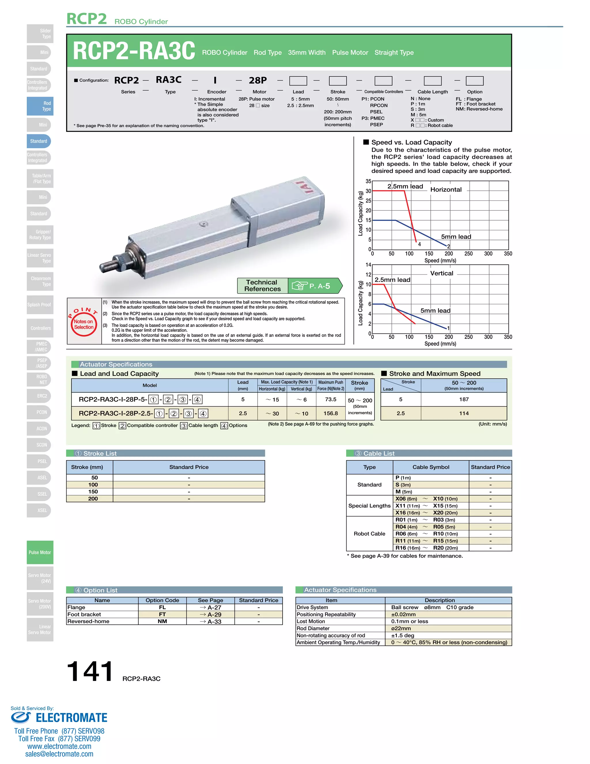

The document provides specifications for the RCP2-RA3C ROBO Cylinder, including: 1) Load capacity decreases at higher speeds for the pulse motor, with graphs showing the relationship between speed and load capacity. 2) Dimensions, weight, and stroke limits for the cylinder. 3) Compatible controller options for operating the cylinder, with descriptions of each controller type.


![Vibe Coding vs. Spec-Driven Development [Free Meetup]](https://cdn.slidesharecdn.com/ss_thumbnails/vibecodingvsspecdrivendevelopment-251209105622-43f455e7-thumbnail.jpg?width=640&height=640&fit=bounds)


