Download to read offline
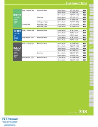
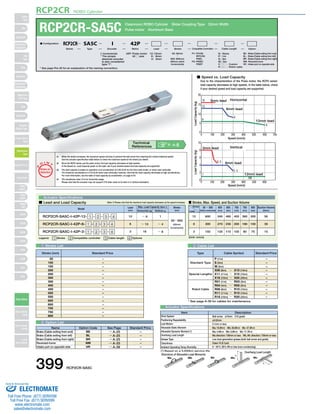
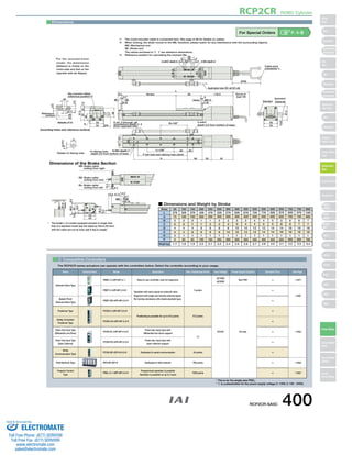
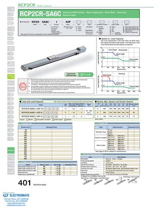
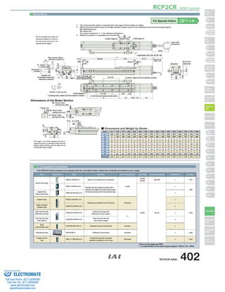
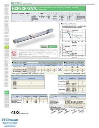
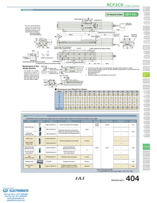
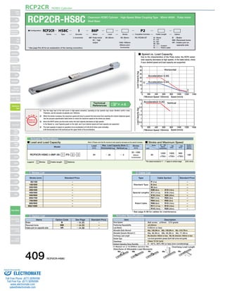
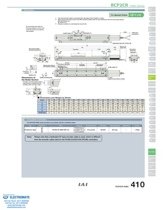
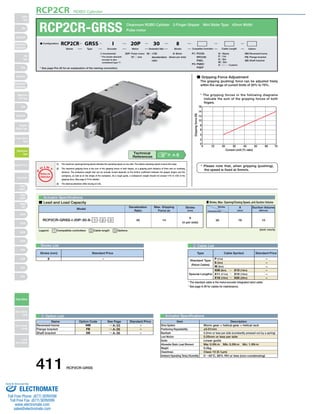
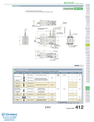

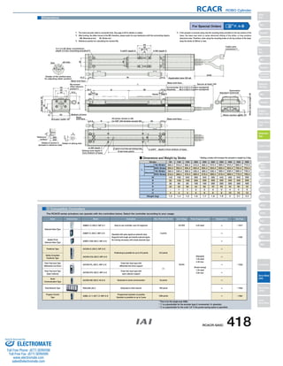
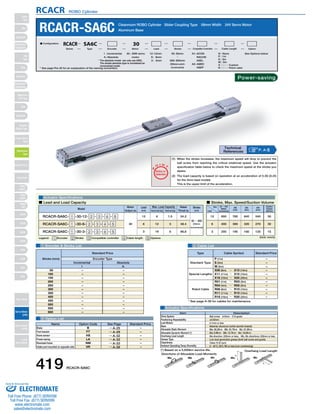
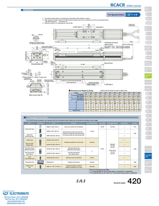
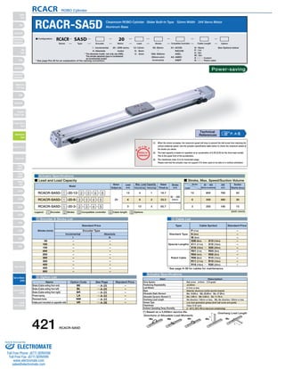
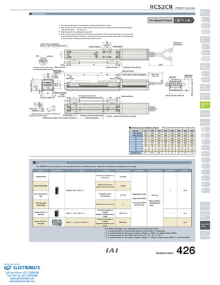
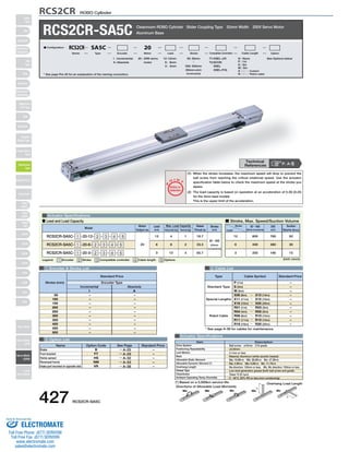
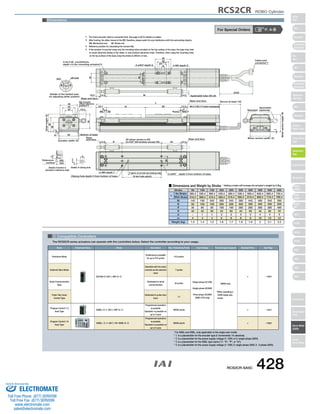
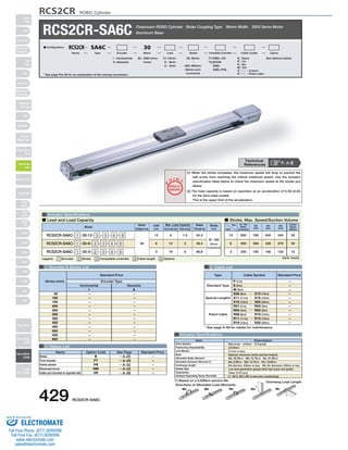
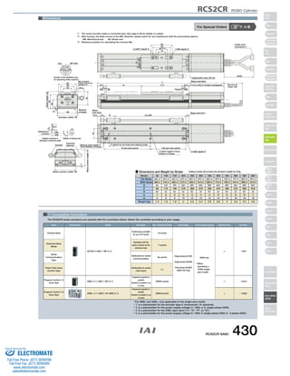

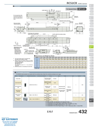
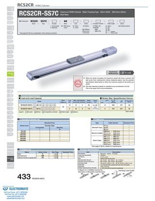
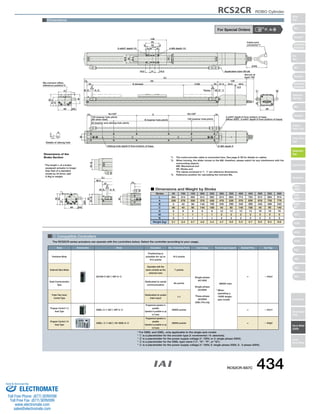
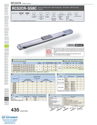

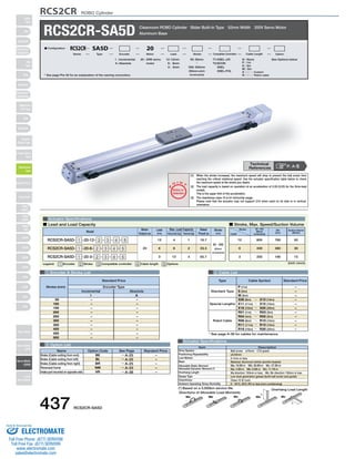
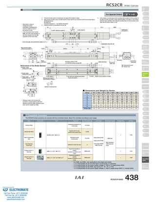

This document provides information about various cleanroom actuator models including: 1. A list of cleanroom actuator types with different slider coupling widths and materials. 2. Specifications for the RCP2CR pulse motor series including maximum speeds, load capacities, dimensions, and compatible controllers. 3. Details for one model, the RCP2CR-SA5C, including a configuration legend, stroke and speed specifications, and dimensional drawings.


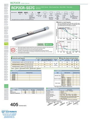
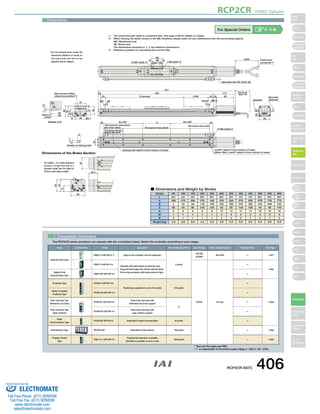
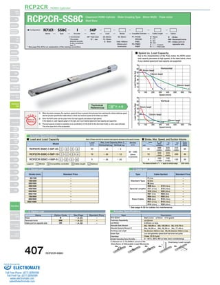
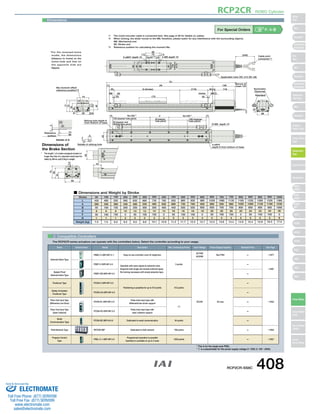
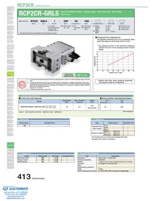
![5G Explained! A High Level Overview [Introduction]](https://cdn.slidesharecdn.com/ss_thumbnails/5gexplainedahighleveloverview-260119165306-cc137a3e-thumbnail.jpg?width=640&height=640&fit=bounds)


