Download to read offline
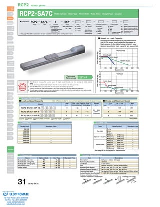


This document provides specifications for the RCP2-SA7C ROBO cylinder slider actuator. It includes details about the actuator such as its configuration, dimensions, load capacity at different speeds, compatible controllers, and more. The maximum load capacity decreases as the speed increases due to the pulse motor characteristics. The document also provides actuator specification tables that list dimensions, weights, and other parameters according to the stroke length.


![Getting Started with Apache Spark: Big Data Made Simple [Free Meetup]](https://cdn.slidesharecdn.com/ss_thumbnails/apachesparkgettingstarted-260203175547-8361bcc3-thumbnail.jpg?width=640&height=640&fit=bounds)


