Download to read offline

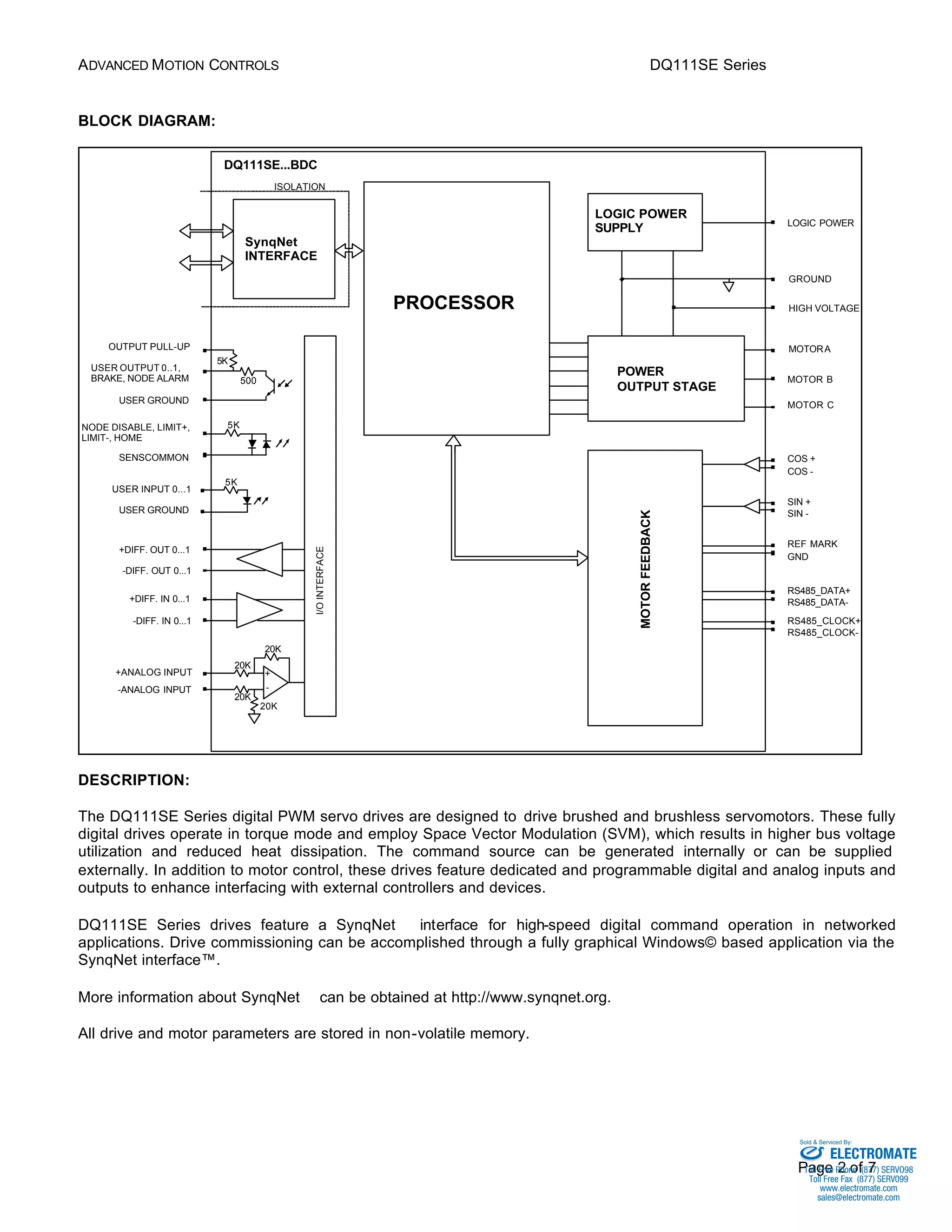
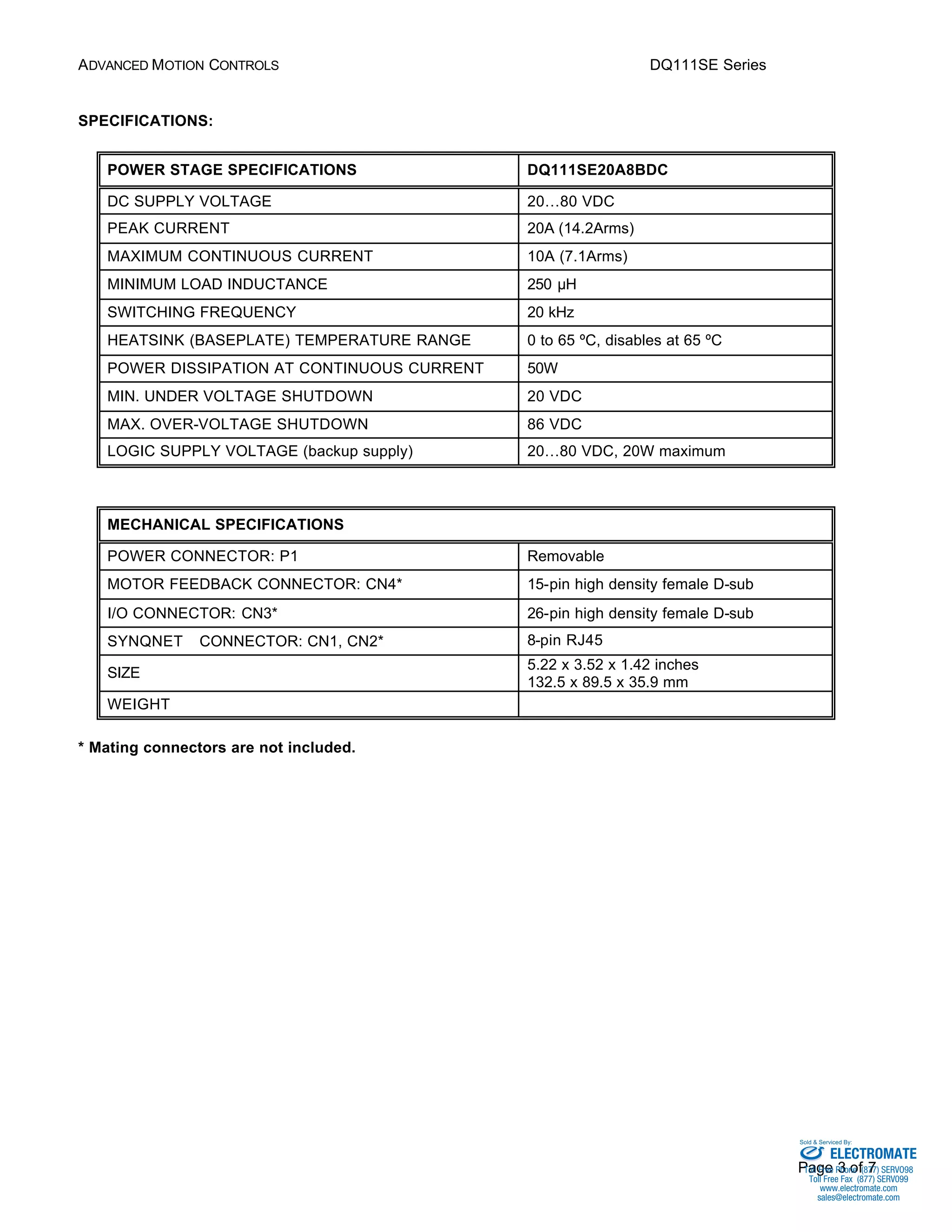
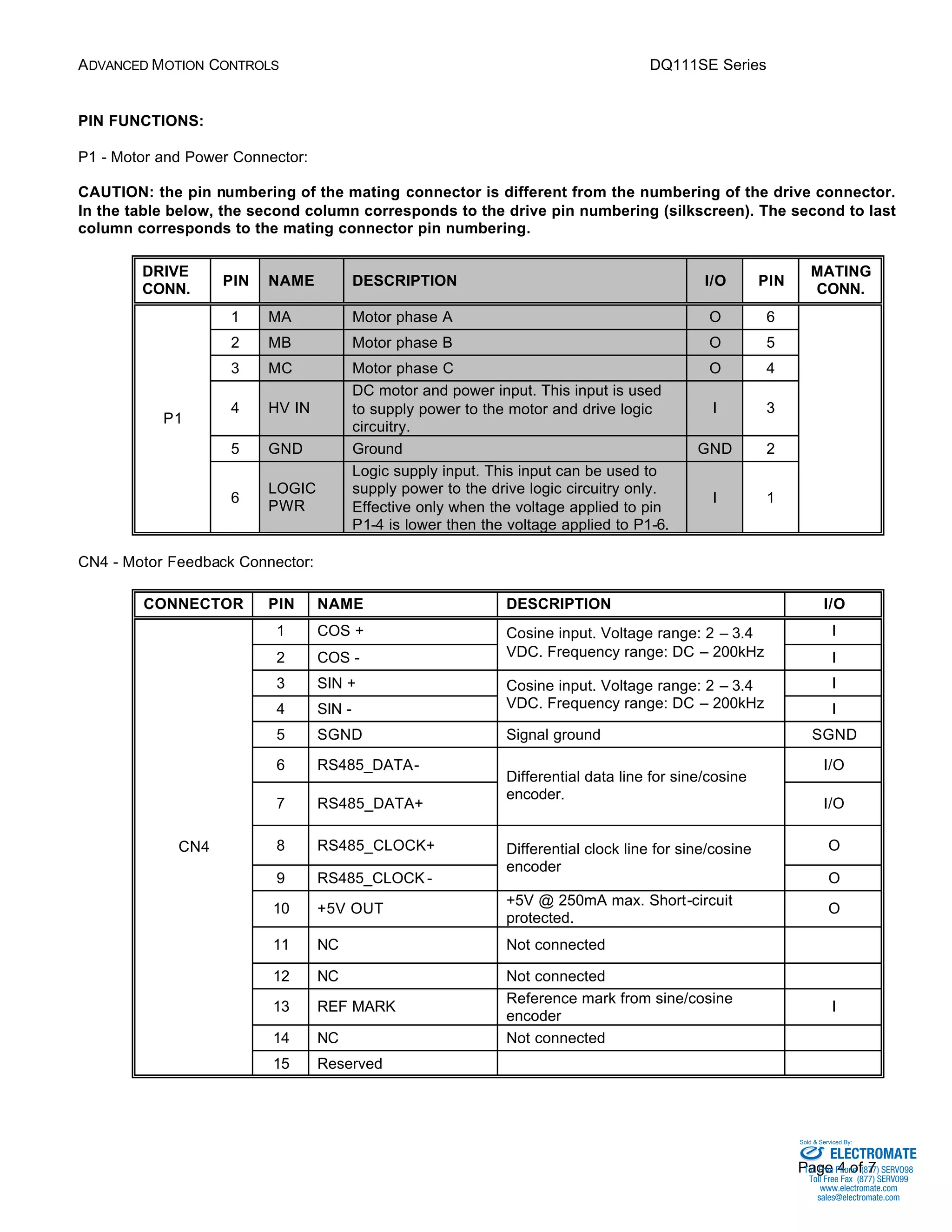
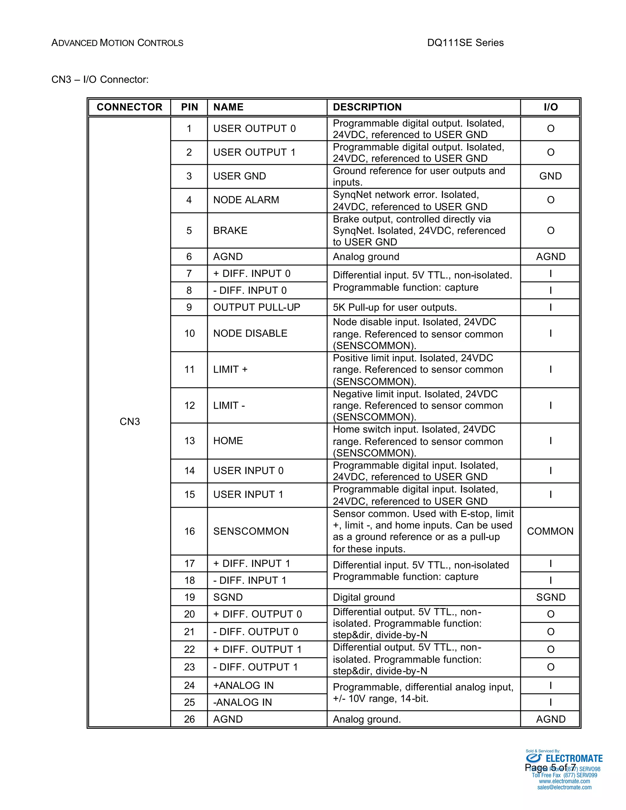
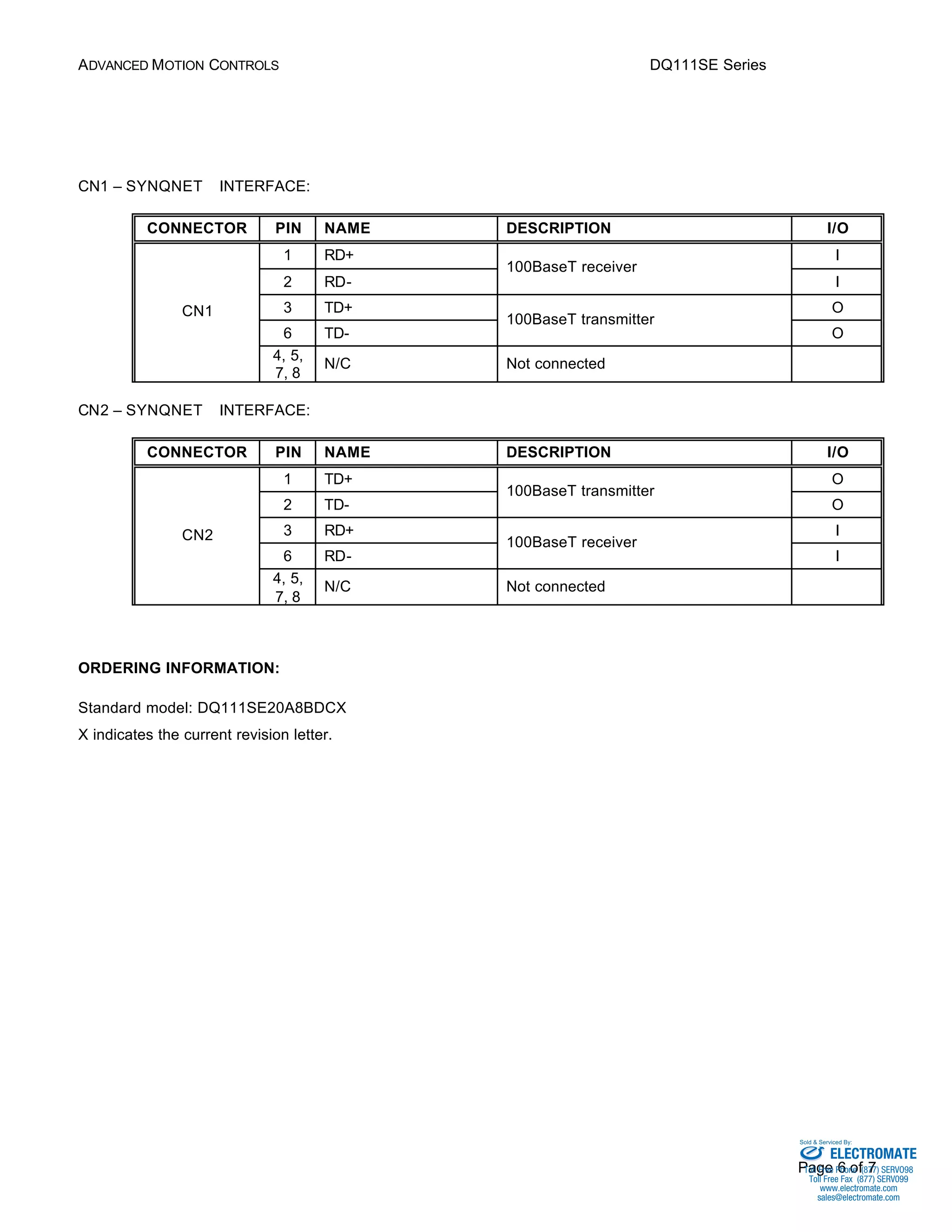

The DQ111SE Series digital servo drives are fully digital devices that employ space vector modulation and vector control technology to drive brushed and brushless motors. They feature a SynqNet interface for networked motion control applications, and include programmable digital and analog inputs and outputs. The drives operate in torque mode, store parameters in non-volatile memory, and provide protection against over-voltage, under-voltage, short-circuits, over-current and over-temperature.


