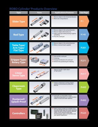
Download to read offline

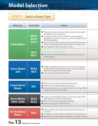
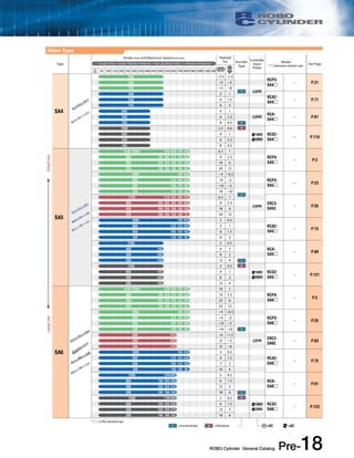
![Model Selection
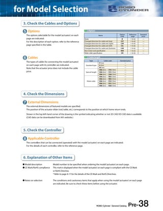
Check Specifications Slider Type
The slider type is used for transporting and positioning work parts. When selecting a slider-type
model, note that the specifications are different when used horizontally versus vertically.
[Selection Conditions for Positioning Operation]
Select a model that meets your conditions of use ([1] maximum speed, [2] distance, [3] weight) from the SPEC list provided below.
[Example]
Selection
Conditions
Stroke (mm) and Maximum Speed (mm/sec) Payload
➀Maximum
Speed
<Notice> If the work part being transported is significantly overhanging from the actuator, the service life of the guide needs to be
considered separately from the actuator's specifications. See "About Service Life and Moment" on page A-5 for details.
Pre-17 ROBO Cylinder General Catalog
(kg)
* Length of bar = stroke *Number inside bar = max. speed by stroke, < > denotes vertical use
25 Horizontal Vertical
mm 50 100 150 200 250 300 350 400 450 500 550 600 700 800 900 1000 1100 1200
1010 790 20 3
865
〈840〉655 515 40 8
1200
980 〈840〉
I =Incremental A =Absolute =DC =AC
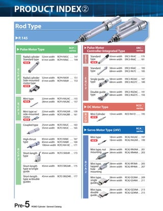
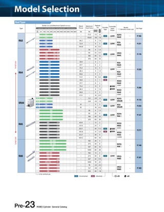
Slider Type
Type
Stroke (mm) and Maximum Speed (mm/sec) Payload
(kg) Encoder
Type
Controller
Input
Power
Model
* denotes motor size See Page * Length of bar = stroke *Number inside bar = max. speed by stroke, < > denotes vertical use
25 Horizontal Vertical mm 50 100 150 200 250 300 350 400 450 500 550 600 700 800 900 1000 1100 1200
SA2
180 200 0.25 −
RCP3-
SA2A
100 0.5 − —
P.15
50 1 −
180 280 300 0.25 −
RCP3-
SA2B
180 200 0.5 − I 24V —
P.17
100 1 −
180 200 0.5 0.25
RCA2-
SA2A
100 1 0.5 —
P.67
50 2 1
SA3
300 1 0.5
RCP3-
SA3
200 2 1 —
P.19
100 3 1.5
I 24V
300 1 0.5
RCA2-
SA3
200 2 1 —
P.69
100 3 1.5
Large size Small size
➁
Distance
➂
Weight
(1) The featured models are arranged by size, starting from the smallest one. Larger models are listed later in the list.
(2) Each motor type is indicated by a different color.
( Green: Pulse motor , Blue: 24-V servo , Gray: 200-V servo motor , Red: Controller-integrated type )
(3) With the pulse motor specification, the payload varies depending on the speed. Check the actual SPEC by
referring to the correlation diagram of speed vs. payload provided on the page featuring each model.
<Notes on the Table>](https://image.slidesharecdn.com/iai01rcgeneralcj0203-2apre1-54intro-141008205230-conversion-gate01/85/Iai-01-rc-general_cj0203-2_a_pre1-54_intro-17-320.jpg)
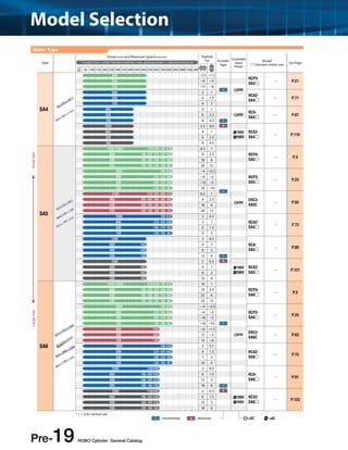
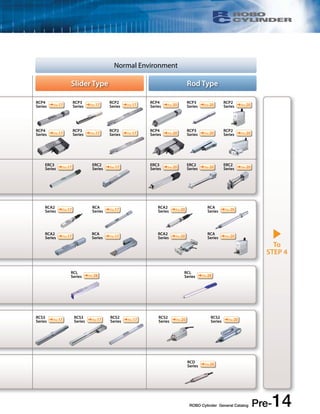
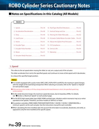
![Check Specifications Rod Type
For the rod type, the criteria for selection are different, depending on whether it will be used for
positioning operation or for push operation.
[Selection Conditions for Positioning Operation]
Select a model that meets your conditions of use ([1] maximum speed, [2] distance, [3] weight) from the SPEC list provided below.
[Example]
Stroke (mm) and Maximum Speed (mm/sec) Rated
Payload
(kg) * Length of bar = stroke *Number inside bar = max. speed by stroke, < > denotes vertical use
Horizontal Vertical 25mm 30 50 75 100 150 200 250 300 (N) (N)
180 200 − 23.1~35.7 1 0.325
100 100 − 46.2~70.6 2 0.625
[Push Operation]
Thrust
Maximum
Push Force
➁ ➂
Distance Weight
Select a model that meets your conditions of use ([1] distance, [2] push force) from the SPEC list provided below.
Stroke (mm) and Maximum Speed (mm/sec) Rated
Payload
(kg) * Length of bar = stroke *Number inside bar = max. speed by stroke, < > denotes vertical use
Thrust
Maximum
Push Force
Horizontal Vertical 25mm 30 50 75 100 150 200 250 300 (N) (N)
180 200 − 23.1~35.7 1 0.325
100 100 − 46.2~70.6 2 0.625
ROBO Cylinder General Catalog Pre-20
Selection
Conditions
[Example]
Selection
Conditions
Refer to page A-71 for the details of the push operation.
Maximum
Speed
➀
➀ Distance ➁ Push force
(1) The featured models are arranged by size, starting from the smallest one. Larger models are listed later in the list.
(2) Each motor type is indicated by a different color.
( Orange: DC servo motor , Green: Pulse motor , Blue: 24-V servo , Gray: 200-V servo motor , Red: Controller-integrated type )
(3) With the pulse motor specification, the payload varies depending on the speed. Check the actual SPEC by
referring to the correlation diagram of speed vs. payload provided on the page featuring each model.
<Notes on the Table>](https://image.slidesharecdn.com/iai01rcgeneralcj0203-2apre1-54intro-141008205230-conversion-gate01/85/Iai-01-rc-general_cj0203-2_a_pre1-54_intro-20-320.jpg)
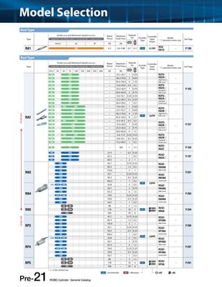
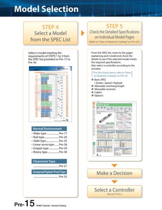
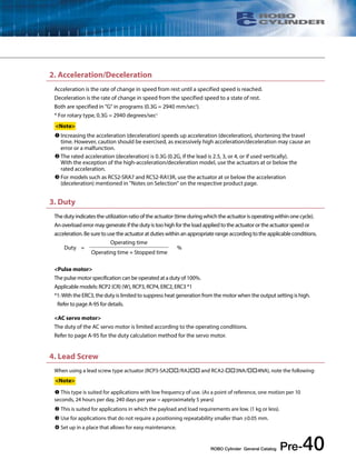
![Model Selection
Check Specifications
[Selection Conditions for Positioning Operation]
Select a model that meets your conditions of use ([1] maximum speed, [2] distance, [3] weight) from the SPEC list provided below.
[Example] Stroke (mm) and Maximum Speed (mm/sec) Rated
Payload
(kg) * Length of bar = stroke *Number inside bar = max. speed by stroke, < > denotes vertical use
100 50.3 − 0.5 0.25 −
50 100.5 − 1 0.5
200 29.8 − 0.5 0.25 −
100 59.7 − 1 0.5
250 − P.351
Pre-25 ROBO Cylinder General Catalog
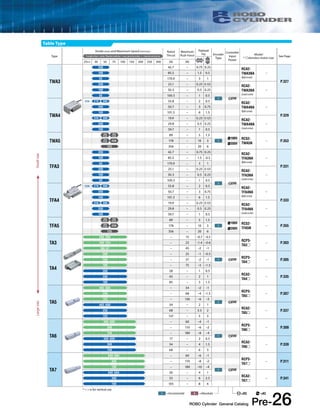
Table Type
Similar to the rod type, the table type can be used for positioning operation and push operation.
The rod type is recommended for pushing motions, as it exerts stronger force and has more variety.
Selection
Conditions
Thrust
Maximum
Push Force
Horizontal Vertical 25mm 30 50 75 100 150 200 250 300 (N) (N)
200 42.7 − 0.75 0.25
100 85.5 − 1.5 0.5
➀Maximum Speed ➁Distance ➂Weight
(1) The featured models are arranged by size, starting from the smallest one. Larger models are listed later in the list.
(2) Each motor type is indicated by a different color.
( Green: Pulse motor , Blue: 24-V servo , Gray: 200-V servo motor )
(3) With the pulse motor specification, the payload varies depending on the speed. Check the actual SPEC by
referring to the correlation diagram of speed vs. payload provided on the page featuring each model.
<Notes on the Table>
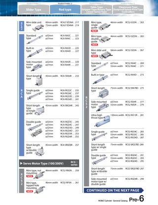
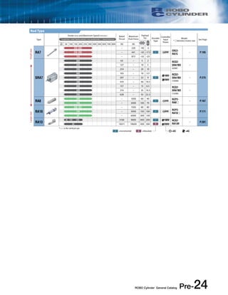
Table Type
Type
Stroke (mm) and Maximum Speed (mm/sec) Rated
Thrust
Maximum
Push Force
Payload
(kg) Encoder
Type
Controller
Input
Power
Model
* denotes motor size See Page * Length of bar = stroke *Number inside bar = max. speed by stroke, < > denotes vertical use
25 Horizontal Vertical mm 30 50 75 100 150 200 250 300 (N) (N)
TCA3
200 42.7 − 0.75 0.25 RCA2-
TCA3NA
(Ball screw)
−
P.323
100 85.5 − 1.5 0.5
50 170.9 − 3 1
200 25.1 − 0.25 0.125 RCA2-
TCA3NA
(Lead screw)
I 24V
TCA4
<220> 270 300 33.8 − 2 0.5 RCA2-
TCA4NA
(Ball screw)
−
P.325
200 50.7 − 3 0.75
100 101.5 − 6 1.5
220 300 19.9 − 0.25 0.125 RCA2-
TCA4NA
(Lead screw)
TCA5
280
〈230〉
380
〈330〉89 − 5 1.5
100V RCS2-
TCA5N
〈230〉250 178 − 10 3 I
125 356 − 20 6
200V
Large size Small size
I =Incremental A =Absolute =DC =AC
* < > is for vertical use](https://image.slidesharecdn.com/iai01rcgeneralcj0203-2apre1-54intro-141008205230-conversion-gate01/85/Iai-01-rc-general_cj0203-2_a_pre1-54_intro-25-320.jpg)
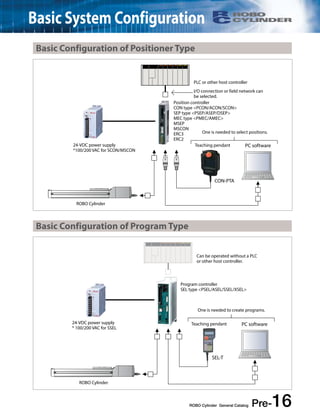
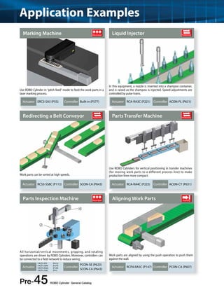
![Stroke (mm) and Maximum Speed (mm/sec) Rated
Payload
(kg) * Length of bar = stroke *Number inside bar = max. speed by stroke, < > denotes vertical use
Thrust
Maximum
Push Force
Horizontal Vertical 25mm 30 40 48 64 100 200 300 (N) (N)
420 2 − 0.5 −
460 4 − 1 −
➁Distance ➂
Weight
➀Maximum Speed
Stroke (mm) and Maximum Speed (mm/sec) Rated
Payload
(kg) * Length of bar = stroke *Number inside bar = max. speed by stroke, < > denotes vertical use
Thrust
Maximum
Push Force
Horizontal Vertical 25mm 30 40 48 64 100 200 300 (N) (N)
300 2.5 2 0.5 0.1
340 5 4 1 0.2
Distance Push force
➀ ➁
ROBO Cylinder General Catalog Pre-28
Check Specifications
[Selection Conditions for Positioning Operation]
[Example]
Selection
Conditions
[Push Operation]
Selection
Conditions
Linear Servo Type
The linear servo type is available as a slider type for positioning operation, or as a rod type for
push operation. See below for the selection criteria.
Select a model that meets your conditions of use ([1] maximum speed, [2] distance, [3] weight) from the SPEC list provided below.
Select a model that meets your conditions of use ([1] distance, [2] push force) from the SPEC list provided below.
[Example]
Refer to page A-71 for the details of the push operation.
<Notes on the Table> (1) The featured models are arranged by size, starting from the smallest one. Larger models are listed later in the list.
Type
Stroke (mm) and Maximum Speed (mm/sec) Rated
Thrust
Maximum
Push Force
Payload
(kg) Encoder
Type
Controller
Input
Power
Model
* denotes motor size See Page * Length of bar = stroke *Number inside bar = max. speed by stroke, < > denotes vertical use
Horizontal Vertical 25mm 30 40 48 64 100 200 300 (N) (N)
SA1L 420 2 − 0.5 − RCL-SA1L − P.419
SA2L 460 4 − 1 − RCL-SA2L − P.421
SA3L 600 8 − 2 − RCL-SA3L − P.423
SA4L 1200 2.5 − 0.8 − RCL-SA4L − P.425
SA5L 1400 5 − 1.6 − RCL-SA5L − P.429
SA6L 1600 10 − 3.2 −
I 24V
RCL-SA6L − P.433
SM4L 1200 2.5 − 0.8 − RCL-SM4L − P.427
SM5L 1400 5 − 1.6 − RCL-SM5L − P.431
SM6L 1600 10 − 3.2 − RCL-SM6L − P.435
RA1L 300 2.5 10 0.5 0.1 RCL-RA1L − P.437
RA2L 340 5 18 1 0.2 RCL-RA2L − P.439
RA3L 450 10 30 2 0.4 RCL-RA3L − P.441
Large size Small size
I =Incremental A =Absolute =DC =AC
Linear Servo Type](https://image.slidesharecdn.com/iai01rcgeneralcj0203-2apre1-54intro-141008205230-conversion-gate01/85/Iai-01-rc-general_cj0203-2_a_pre1-54_intro-28-320.jpg)
![Model Selection
Check Specifications
[Push Operation]
Select a model that meets your conditions of use ([1] distance, [2] grip force) from the SPEC list provided below.
[Example]
Selection
Conditions
Stroke (mm) and Maximum Speed (mm/sec)
➀ ➁
[Selection Conditions for Positioning Operation]
Select a model that meets your conditions of use ([1] maximum speed, [2] distance) from the SPEC list provided below.
[Example]
Distance
Maximum
speed
Pre-29 ROBO Cylinder General Catalog
Gripper type
The gripper type is used for gripping and centering work parts. Gripping is done by a pushing
operation, and centering is done by a positioning operation.
Selection
Conditions
Refer to page A-71 for the details of the push operation.
Maximum
Grip Force
8mm 10mm 14mm 20mm 32mm 40mm 60mm 100mm 120mm 200mm 19deg. 180deg. (N)
78 14
600 6.4
Stroke (mm) and Maximum Speed (mm/sec)
Maximum
Grip Force
8mm 10mm 14mm 20mm 32mm 40mm 60mm 100mm 120mm 200mm 19deg. 180deg. (N)
78 14
600 6.4
➀
➁
Distance
Grip force
(Push force)
<Notes on the Table> (1) Each motor type is indicated by a different color. ( Green: Pulse motor , Gray: 200-V servo motor )
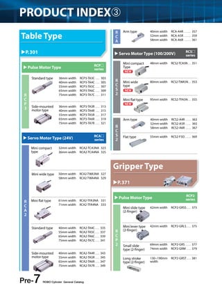
Gripper Type
Type
Stroke (mm) and Maximum Speed (mm/sec) Maximum
Grip Force Encoder
Type
Controller
Input
Power
Model
* denotes motor size See Page
8mm 10mm 14mm 20mm 32mm 40mm 60mm 100mm 120mm 200mm 19deg. 180deg. (N)
GRSS 78 14 RCP2-GRSS − P.373
GRLS 600 6.4 RCP2-GRLS − P.375
GRS 33.3 21 RCP2-GRS − P.377
GRM 36.7 80
24V
RCP2-GRM − P.379
GRST
75 20
RCP2-GRST − P.381
34 40
GRHM 100 125
I
RCP2-GRHM − P.383
GRHB 100 200 RCP2-GRHB − P.385
GR8 (60cpm) 45.1
100V RCS2-GR8 − P.395 200V
GR3LS 200 18 RCP2-GR3LS − P.387
GR3LM 200 51
24V
RCP2-GR3LM − P.389
GR3SS 40 22 RCP2-GR3SS − P.391
GR3SM 50 102 RCP2-GR3SM − P.393
Large size Small size
I =Incremental A =Absolute =DC =AC](https://image.slidesharecdn.com/iai01rcgeneralcj0203-2apre1-54intro-141008205230-conversion-gate01/85/Iai-01-rc-general_cj0203-2_a_pre1-54_intro-29-320.jpg)
![Rotary Type
For the rotary type, a model is selected for its positioning operation generated by the rotating part.
[Selection Conditions for Positioning Operation]
Select a model that meets your conditions of use ([1] maximum speed, [2] oscillating angle, [3] inertial moment) from
the SPEC list provided below.
[Example] Oscillating Angle (mm) and Maximum Speed (mm/sec)
ROBO Cylinder General Catalog Pre-30
Check Specifications
Selection
Conditions
Maximum
Torque
Allowable
Inertial Moment
300deg. 330 360 (N) kg•m2
400 0.24 0.0023
266 0.36 0.0035
➀ ➁ ➂
Maximum speed Oscillating angle Inertial moment
<Notes on the Table> (1) Each motor type is indicated by a different color. ( Green: Pulse motor , Gray: 200-V servo motor )
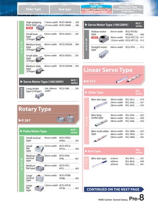
Rotary Type
Type
Oscillating Angle (mm) and Maximum Speed (mm/sec)
Maximum
Torque
Allowable
Inertial Moment Encoder
Type
Controller
Input
Power
Model
* denotes motor size See Page
300deg. 330 360 (N) kg•m2
RTBS
400 0.24 0.0023
RCP2-RTBS −
P.397
266 0.36 0.0035
RTBSL
400 0.24 0.0023
RCP2-RTBSL −
266 0.36 0.0035
RTCS
400 0.24 0.0023
RCP2-RTCS −
P.399
266 0.36 0.0035
RTCSL
400 0.24 0.0023
RCP2-RTCSL −
266 0.36 0.0035
RTB
600 1.1 0.01
RCP2-RTB −
P.401
400 1.7 0.015
RTBL
600 1.1 0.01
RCP2-RTBL −
400 1.7 0.015
I 24V
RTC
600 1.1 0.01
RCP2-RTC −
P.403
400 1.7 0.015
RTCL
600 1.1 0.01
RCP2-RTCL −
400 1.7 0.015
RTBB
600 3 0.02
RCP2-RTBB −
P.405
400 4.6 0.03
RTBBL
600 3 0.02
RCP2-RTBBL −
400 4.6 0.03
RTCB
600 3 0.02
RCP2-RTCB −
P.407
400 4.6 0.03
RTCBL
600 3 0.02
RCP2-RTCBL −
400 4.6 0.03
RTC8L 750 0.55 0.011 RCS2-RTC8L − P.409
1200 0.53 0.01 RCS2-
RTC8HL
RTC8HL
− P.409
750 0.85 0.017
I
RTC10L
1200 1.7 0.033 RCS2-
RTC10L
− P.411
750 2.8 0.054
A
100V
RTC12L
800 5.2 0.1 200V RCS2-
RTC12L
− P.413
600 8.6 0.17
RT6 500 2.4 0.025 I RCS2-RT6 − P.415
Large size Small size
I =Incremental A =Absolute =DC =AC](https://image.slidesharecdn.com/iai01rcgeneralcj0203-2apre1-54intro-141008205230-conversion-gate01/85/Iai-01-rc-general_cj0203-2_a_pre1-54_intro-30-320.jpg)
![Model Selection
Check Specifications
[Selection Conditions for Positioning Operation]
Select a model that meets your conditions of use ([1] maximum speed, [2] distance, [3] weight) from the SPEC list provided below.
[Example] Stroke (mm) and Maximum Speed (mm/sec) Payload
Selection
Conditions
(1) The featured models are arranged by size, starting from the smallest one. Larger models are listed later in the list.
(2) Each motor type is indicated by a different color.
( Green: Pulse motor , Blue: 24-V servo , Gray: 200-V servo motor , Red: Controller-integrated type )
(3) With the pulse motor specification, the payload varies depending on the speed. Check the actual SPEC by
referring to the correlation diagram of speed vs. payload provided on the page featuring each model.
<Notes on the Table>
Pre-31 ROBO Cylinder General Catalog
Cleanroom Type
The cleanroom type is used for transporting and positioning work parts. When selecting a cleanroom
type model, note that the specifications are different when used horizontally versus vertically.
Type
Stroke (mm) and Maximum Speed (mm/sec) Payload
(kg) Encoder
Type
Controller
Input
Power
Model
* denotes
motor size
See
Page
* Length of bar = stroke *Number inside bar = max. speed by stroke, < > denotes vertical use
Horizontal Vertical 25mm 50 100 150 200 250 300 350 400 450 500 550 600 700 800 900 1000 1100
SA4
665 4 1
I RCACR-SA4C
330 6 2.5 24V − P.465
A
165 8 4.5
665 4 1
I 100V RCS2CR-SA4C
330 6 2.5 − P.479
A 200V
165 8 4.5
Cleanroom Type
(kg)
* Length of bar = stroke *Number inside bar = max. speed by stroke, < > denotes vertical use
Horizontal Vertical 25mm 50 100 150 200 250 300 350 400 450 500 550 600 700 800 900 1000 1100
665 4 1
330 6 2.5
➀ ➁ ➂
Distance
Maximum
speed
Weight
<Note: > If the work part being transported is significantly overhanging from the actuator, the service life of the guide needs to be
considered separately from the actuator's specifications. See "About Service Life and Moment" on page A-5 for details.
Large size Small size
I =Incremental A =Absolute =DC =AC
* < > is for vertical use](https://image.slidesharecdn.com/iai01rcgeneralcj0203-2apre1-54intro-141008205230-conversion-gate01/85/Iai-01-rc-general_cj0203-2_a_pre1-54_intro-31-320.jpg)
![Model Selection
Check Specifications
[Selection Conditions for Positioning Operation]
[Example]
Selection
Conditions
➀ ➁ ➂
[Push Operation]
Selection
Conditions
Stroke (mm) and Maximum Speed (mm/sec) Rated
Pre-33 ROBO Cylinder General Catalog
Dustproof/Splash-Proof Type
The criteria for selecting the dustproof/splash-proof type are different depending on whether it will be
used for positioning operation or push operation.
Select a model that meets your conditions of use ([1] maximum speed, [2] distance, [3] weight) from the SPEC list provided below.
Thrust
Select a model that meets your conditions of use ([1] distance, [2] push force) from the SPEC list provided below.
[Example]
Refer to page A-71 for the details of the push operation.
Maximum
Push Force
Payload
(kg)
* Length of bar = stroke *Number inside bar = max. speed by stroke, < > denotes vertical use
Horizontal Vertical 50mm 100 150 200 250 300 350 400 450 500 550 600 650 700 (N) (N)
330 − 66.9 5 −
165 − 147.9 10 −
Stroke (mm) and Maximum Speed (mm/sec) Rated
Thrust
Maximum
Push Force
Payload
(kg)
* Length of bar = stroke *Number inside bar = max. speed by stroke, < > denotes vertical use
Horizontal Vertical 50mm 100 150 200 250 300 350 400 450 500 550 600 650 700 (N) (N)
500 560 <500> − 93 20 3
360 − 185 40 8
➀
Distance
Maximum
speed
Weight
Distance
➁
Push
force
(1) The featured models are arranged by size, starting from the smallest one. Larger models are listed later in the list.
(2) Each motor type is indicated by a different color.
( Green: Pulse motor , Blue: 24-V servo , Gray: 200-V servo motor )
(3) With the pulse motor specification, the payload varies depending on the speed. Check the actual SPEC by
referring to the correlation diagram of speed vs. payload provided on the page featuring each model.
<Notes on the Table>](https://image.slidesharecdn.com/iai01rcgeneralcj0203-2apre1-54intro-141008205230-conversion-gate01/85/Iai-01-rc-general_cj0203-2_a_pre1-54_intro-33-320.jpg)
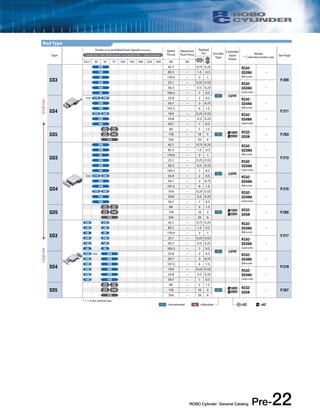
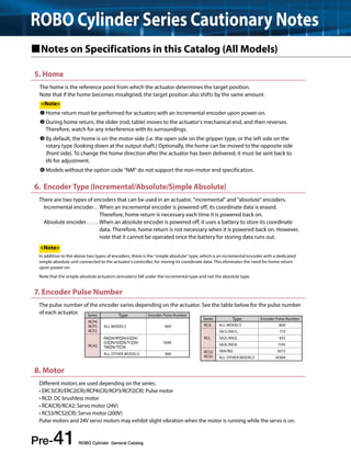
![Explanation of Items in This Catalog Check the Basic SPEC
Diagram of Speed vs. Payload
➊ Correlation Diagram of Speed vs. Payload
25
With pulse motor models (RCP4, RCP3, RCP2, ERC3 and ERC2), the maximum speed
20
Lead 3
The values for leads 3/6/12 are
based on operation at 0.3 G.
18
Lead 6
varies depending on the payload.
Horizontal
15
Refer to the correlation diagram of speed vs. payload to check if the model selected
99
from the SPEC list meets the required speed and payload.
10
Lead 12 Lead 20
6.5
(operation at 0.3 G)
Also note that the specification values of the RCP4 series are different depending
5
66
66 on whether the high-output controller (PCON-CA) or non-high-output controller
Lead 20 (operation at 0.5 G)
1
(MSEP) is used.
➋ The values in < > apply when the
Stroke vs. Maximum Speed
actuator is used vertically.
The longer the stroke, the lower the maximum speed becomes
to prevent the ball screw from reaching the dangerous number
of revolutions.
Refer to the table of stroke vs. maximum speed to check if the
selected model meets the required maximum speed.
* Take note that, if the travel distance is short, the maximum speed may not
be reached.
➌ Lead vs. Payload
Lead vs. Payload
Model number Lead
Connected
Maximum payload Stroke
The lead indicates the feed range per one revolution
(mm)
controller
Horizontal (kg) Vertical (kg) (mm)
of the ball screw or lead screw.
PCON-CA 6.5 1
RCP4-SA5C-I-42P-20- ➀ -P3- ➁ - ➂ 20
MSEP-C 4 0.5 (*)
The greater the value of lead, the higher the speed
PCON-CA 9 2.5
RCP4-SA5C-I-42P-12- ➀ -P3- ➁ - ➂ 12
becomes, but the payload decreases.
MSEP-C 6 2
50~800
PCON-CA 18 6
(in 50mm
The smaller the value of lead, on the other hand, the
RCP4-SA5C-I-42P-6- ➀ -P3- ➁ - 6
increments)
➂ MSEP-C 13 5
greater the payload becomes, but the maximum
PCON-CA 20 12
RCP4-SA5C-I-42P-3- ➀ -P3- ➁ - ➂ 3
MSEP-C 16 10
speed decreases.
Explanation of symbols ➀ Stroke ➁ Cable length ➂ Option(s)
(*) The value is based on
0.2 G of acceleration.
2. Check the Allowable Overhang Length and Allowable Moment
➍ Actuator Specifications
Actuator Specifications
When selecting an actuator, you must check not only the
Drive method Ball screw, ø10mm, rolled, C10
operating performance, but also the rigidity and life of
Positioning repeatability (*1) ±0.02mm [±0.03mm]
the actuator. Check the following items in the actuator
Lost motion 0.1mm or less
Base Material: Aluminum with white alumite treatment
specification table.
Guide Linear guide
(For the detailed explanation of each item, refer
Dynamic allowable moment (*2) 4.9 N•m in Ma direction, 6.8 N•m in Mb direction, 11.7 N•m in Mc direction
Allowable overhang length 150mm or less in Ma direction, 150mm or less in Mb/Mc directions
to the glossary of terms at the end.)
Ambient operating temperature, humidity 0 to 40°C, 85% RH or less (non-condensing)
(*1) The value in [ ] assumes a lead of 20. (*2) Based on a traveling life of 5,000 km.
• Drive method Different drive methods are available,
such as the ball screw type, lead
screw type and belt type, depending
on the model.
Item Description
• Positioning repeatability While the positioning repeatability of the ball screw specification is normally 0.02mm, it
worsens to ±0.03mm on models with larger screw leads. With the belt specification, the
positioning repeatability is considered ±0.1 mm in consideration of the belt elongation, etc.
• Dynamic allowable moment Take note that using the actuator at moments beyond its dynamic allowable moment will
significantly shorten the life of the actuator. Check the actual moments that will generate in your
specific application according to the calculation methods explained on page A-5 of this catalog.
• Overhang load length Take note that using the actuator at overhang load lengths beyond the specified value may
cause abnormal noise or vibration to generate.
Pre-37 ROBO Cylinder General Catalog
RCP4-SA5C, horizontal, PCON-CA connected
Speed (mm/s)
0
0 200 400 600 800 1000 1200 1400 1600
Payload (kg)
Stroke and Maximum Speed (unit: mm/s)
Lead
Stroke
(mm)
Controller
55~450
(50mm)
500
(mm)
550
(mm)
600
(mm)
650
(mm)
700
(mm)
750
(mm)
800
(mm)
20
PCON-CA 1440<1280> 1225 1045 900 785 690 610
MSEP-C 960 900 785 690 610
12
PCON-CA 900 795 665 570 490 425 375 330
MSEP-C 600 570 490 425 375 330
6
PCON-CA 450 395 335 285 245 215 185 165
MSEP-C 300 285 245 215 185 165
3
PCON-CA 225 195 165 140 120 105 90 80
MSEP-C 150 140 120 105 90 80
Drive method Features
Ball screw High accuracy, long life
Lead screw Low cost, low noise
Belt The maximum speed does not drop at long strokes.](https://image.slidesharecdn.com/iai01rcgeneralcj0203-2apre1-54intro-141008205230-conversion-gate01/85/Iai-01-rc-general_cj0203-2_a_pre1-54_intro-37-320.jpg)
![Description of Models
Each ROBO Cylinder model is defined by the items (codes) below.
See descriptions below for the meaning of each item. The range of selectable values for each item (e.g. lead,
stroke, etc.) is different for each product type. See each type for details.
[Actuator] Description of Items
Series − Type − Encoder − Motor − Lead − Stroke − Compatible
Pre-47 ROBO Cylinder General Catalog
Controllers − Cable Length − Option
Series Indicates the name of the series.
Type
Indicates the product type (slider, rod, etc.), material (aluminum, steel, etc.), actuator size (52 mm width,
etc.), and motor connection method, using the convention below:
e.g. SA5C
Type: Slider
Material: Aluminum
Actuator width: 52mm
Motor: Coupled
* Gripper and rotary type ROBO
Cylinders have their own
naming convention.
Type Material / Form Actuator width Motor connection
method
S (Slider)
B (Belt)
R (Rod)
H (High-speed)
T (Table)
A (Arm)
F (Flat)
SR (Short rod)
A (Aluminum)
S (Steel)
GS (Single guide)
GD (Double guide)
SD (Slide unit)
N (Nut mounting type)
P (Tapped hole mounting type)
C (Compact)
W (Wide)
F (Flat)
1 (12 width)
2 (22/25/28 width)
3 (30 width)
4 (40/42/45 width)
5 (52/54/55 width)
6 (58/64 width)
7 (60/68 width)
7A (width 75, rod 30)
7B (width 75, rod 35)
8 (80 width)
10 (100 width)
16 (158 width)
C (Coupled)
D (Built-in)
R (Side-mounted)
U(Bottom-mounted)
N (Hollow motor)
L (Linear motor)
Encoder
Indicates whether the actuator is equipped with an absolute or incremental encoder.
A: Absolute
Since the current slider position is retained even after the power is turned
off, home return is not required.
I: Incremental
Since the position data for the slider becomes lost when the power is
turned off, home return is required each time the power is turned on.
Motor
Indicates the power output (W) of the motor used in the actuator.
All ERC2 series products are labeled as PM.
For the RCP4/RCP3/RCP2/ERC3 series, which use a pulse motor, this code indicates the motor size
instead of the power output (e.g. 20P = 20mm frame size motor).
Lead Indicates the ball screw lead (the distance the slider travels as the ball screw completes one revolution).
Stroke Indicates the stroke (range of motion) of the actuator (in mm or degrees).
Compatible
controllers
(I/O type)
Indicates the type of controllers that can be connected.
For the ERC3/ERC2 series, which has a built-in controller, this code indicates the type of
I/O (input/output signals).
Cable length Indicates the length of the motor-encoder cables, which connects the actuator and the controller.
Options
Indicates the options added to the actuator. (See Technical Reference on page A-37 for details.)
*To select multiple options, specify them in alphabetical order (e.g. A3-B-FT)
*When specifying a side-mounted motor type, make sure to include the code (ML or MR) to indicate on
which side the motor is to be mounted.
](https://image.slidesharecdn.com/iai01rcgeneralcj0203-2apre1-54intro-141008205230-conversion-gate01/85/Iai-01-rc-general_cj0203-2_a_pre1-54_intro-47-320.jpg)
![Each model of controller is defined by the items (codes) below.
See descriptions below for the meaning of each item.
Also note that the selection range for each item (I/O type, power-supply voltage, etc.) varies from one controller
to another. Check the details on the page featuring each controller.
[Controller] Description of Items
Single-axis type ‹PMEC, AMEC, PSEP, ASEP, DSEP, PCON, ACON, SCON›
Series − Type − Motor − Encoder − Option − I/O type − I/O cable
length − Power-supply
voltage − Other
ROBO Cylinder General Catalog Pre-48
Multi-axis type ‹MSEP, MSCON, PSEL, ASEL, SSEL, XSEL›
Series
Name of each controller series.
Since the available series vary from one actuator to another, check the connectable controllers on the
“Applicable Controllers” table on the page featuring each actuator.
Type
The type varies depending on the function and connected actuator. Select a type matching your
application by referring to the page featuring each controller.
Number of
connected axes Number of actuator axes to be connected to the controller.
Motor Motor type of the actuator to be connected to the controller.
Encoder Encoder type of the actuator to be connected to the controller.
Option
Option(s) of the actuator to be connected to the controller (such as high-acceleration/deceleration
specification).
I/O Type of I/O signals to connect the controller and external equipment.
I/O cable length
Length of the I/O cable to be supplied when the PIO specification is selected in above. If the field
network specification is selected, the I/O cable is not supplied and therefore this field is automatically
populated by “0.”
Power voltage Type of the power to be supplied to the controller.
Other
Whether or not the controller supports the simple absolute specification and whether the high-acceleration/
payload specification is available, among others.
Series − Type − Number of
connected axes − Motor − Encoder − Option − I/O type − I/O cable
length − Power-supply
voltage voltage − Other
(should be specified separately for each of all connected axes.)](https://image.slidesharecdn.com/iai01rcgeneralcj0203-2apre1-54intro-141008205230-conversion-gate01/85/Iai-01-rc-general_cj0203-2_a_pre1-54_intro-48-320.jpg)
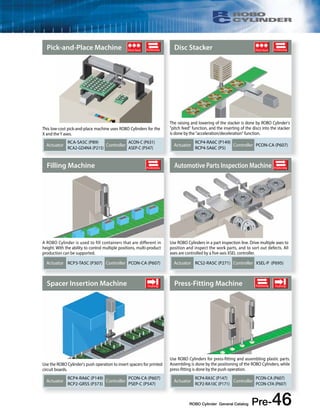
![Description of Functions
Perform Various Functions Through Easy Operations
3 Types of Operation Patterns
Switch between three operation patterns depending on the equipment.
3 Methods of Positioning
Select from 3 types of I/O between the upper-level machine and the controller.
[Position Movement]
As with the solenoid valve, movement
to preset positions is possible with just
an ON/OFF signal.
Operated by I/O control with the PLC
PLC
I/O
Position Data
Output signals
such as current
position and
alarm signals
Input signals
such as for
specifying
position,
pausing, etc.
[Pulse Train Input]
The destination, speed and
acceleration can be freely controlled
without inputting the destination
beforehand.
Operated by pulse trains from the PLC and
I/O control
Pre-49 ROBO Cylinder General Catalog
[Field Network]
Movement can be instructed via a
network, such as DeviceNet and
CC-Link. Work parts can be moved by
specifying the position, or by directly
specifying the coordinates.
Signal is output
on entering zone
Zone signal
PLC
No Sensor Necessary with Zone Signal
You can set any zone within the stroke, and when
the slider enters the zone, the signal is output.
This is effective for outputting signals at a specific
position, such as in painting, for example, (up to 2
zones can be specified). In addition, as a new
feature, P-Zone signals can be set per position.
Although the output signal is the same, a zone
range of up to 256 points can be set.
Output signals
such as
positioning
complete and
alarm signals
(Pulse train)
Signals such
as destination,
speed and
acceleration
Pulse train
I/O
Operated from the PLC via network
Various status
signals current
position
Gateway
unit
(Field network)
Specify position
Specify
destination
directly
PLC
[Positioning Operation]
Objects attached to the slider axis and
rod can be moved to be positioned with
a positioning repeatability of ±0.02 mm.
Application Transporting work part,
positioning camera
Used in a pick-and-place unit
[Push Operation]
Similar to an air cylinder, a rod can
be used to push on a work part
continuously.
Application Press-fitting work part,
clamping
Used for pushing work parts
[Pitch Feed Operation]
Instead of positioning by specifying
coordinates from the home, the
object is moved over a specified
distance from the current position.
Application Raising/lowering stacker,
moving pallet
Used for sending work parts in a
marking process](https://image.slidesharecdn.com/iai01rcgeneralcj0203-2apre1-54intro-141008205230-conversion-gate01/85/Iai-01-rc-general_cj0203-2_a_pre1-54_intro-49-320.jpg)
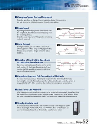
![Positioning Operation
Objects attached to the slider axis and rod can be moved to be positioned with a positioning repeatability
of ±0.01mm to ±0.1mm (*). (*) Varies depending on a model.
200mm/sec
100mm/sec
Acceleration Deceleration Acceleration Deceleration
➁ ➂➃ ➄ ➅ ➆➇
Movement
complete
For PMEC, AMEC, PSEP, ASEP and DSEP
Replacing Single Solenoid
Forward
end position
Backward
end position
Replacing Double Solenoid
* Forward and backward
positions can be freely set.
Forward
end position
Backward
end position
ROBO Cylinder General Catalog Pre-50
Speed
Time
Start signal input
(movement starts)
Positioning
complete signal
output
Position 2 input Start signal input
(movement starts)
Positioning
complete signal
output
Operation
Example
Stopped
Position 1
Position 1 input
Position 2
➀
➀ ➁ ➂ ➃
➄ ➅ ➆ ➇
Movement
complete
No. Position
(mm)
Speed
(mm/sec)
Acceleration
(G)
Deceleration
(G)
Push
(%)
Positioning
band (mm)
1 100 100 0.3 0.3 0 10
2 200 200 0.3 0.3 0 20
Used for opening/
closing a door
Used in a pick-and-place
unit
Application: Transporting/moving work part, etc.
Position Data Table
(set by the teaching pendant or PC software)
[Features]
Capable of positioning up to 512 points.
Set speed and acceleration/deceleration per position.
The positioning complete signal can be output at any
position ahead of the specified position, depending on
the positioning band setting.
Acceleration and deceleration can be set separately.
Speed can be changed in transit without stopping.
PMEC, AMEC, PSEP, ASEP and DSEP can be operated with the same signals as the solenoid valve
Operating Method
PMEC, AMEC, PSEP, ASEP and DSEP can be operated with the same signals as the solenoid valve in air cylinders.
There are two types of solenoid valves, the single solenoid and the double solenoid; and both are supported.
For Air Cylinder Solenoid Valve
Single Solenoid
(Air Cylinder)
Solenoid 1
Forward
end position
Backward
end position
Forward
end position
Backward
end position
Solenoid 1 Solenoid 2
Signal to
solenoid 1
Signal to
solenoid 1 Rod movement
ON Forward end position
OFF Backward end position
Signal to
solenoid 2 Rod movement
ON OFF Forward end position
OFF ON Backward end position
Double Solenoid
(Air Cylinder)
(Solenoid valve)
(Solenoid valve)
Signal to
controller input 1 Rod movement
ON Forward end position
OFF Backward end position
Signal to
controller input 1
Signal to
controller input 0 Rod movement
ON OFF Forward end position
OFF ON Backward end position
(ROBO Cylinder)
( PMEC/AMEC/
PSEP/ASEP/DSEP)
(ROBO Cylinder)
( PMEC/AMEC/
PSEP/ASEP/DSEP)
* Although it is set to 2-point movement by default, 3-point
movement is also possible by switching the parameter.](https://image.slidesharecdn.com/iai01rcgeneralcj0203-2apre1-54intro-141008205230-conversion-gate01/85/Iai-01-rc-general_cj0203-2_a_pre1-54_intro-50-320.jpg)
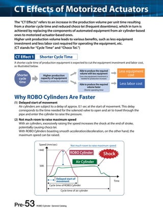
![Description of Functions
In addition to positioning by specifying coordinates from the home, the work part can be moved over a
specified distance from the current position.
Raising/lowering stacker
Used for sending work parts
in a marking process
Application: Raising/lowering stacker, moving pallet, etc.
[Features]
Repeated movements with even spacing can be
performed using one position data, instead of setting
multiple positions.
The pitch can be easily set in the position data table.
Holding work part
in place
Pre-51 ROBO Cylinder General Catalog
Note PMEC/AMEC/PSEP/ASEP controllers
Position No. Position 0
Coordinate 0
have no pitch feed function.
100 25 25 25 25
Position 1
Coordinate 100
Position 2
Coordinate 25
Stopped
Time
Speed
➀ ➁➂
➃
➀
Position 1 input
Start signal input
(positioning
mode)
➁
Position 1
Movement to
100mm position
complete
➂
Position 2 input
25mm with start
signal input (pitch
feed mode)
➃
Position 2
For every start
command signal,
it moves in 25mm
increments
Operation
Example
300mm/sec
Stopped
Time
Speed
Note:
Work part
Positioning band 50
* If the work part does not
reach the positioning band,
the positioning complete
signal is not output.
➄
➄
➂
➁ ➃
Position 1
Coordinate 100
➀
The accuracy of the stationary push force is not guaranteed. Please use it only
as a rough estimate. Please note that if the push force is too small, the push
operation may not be completed properly due to sliding resistance.
Pitch Feed Function (Incremental Function)
Push Operation
Similar to an air cylinder, a rod can be used to push on a work part continuously.
Pushing work parts
Application: Detecting work part, press-fitting, clamping, etc.
[Features]
Since the positioning complete signal
is output when the actuator pushes
against the work part, you can use
it with the zone signal to sort work
parts.
The force against the work part (push
force) can be adjusted by changing
the setting in the position data table.
Position Data Table
(set by the teaching pendant or PC software)w
Position Data Table
(set by the teaching pendant or PC software)w
No. Position
(mm)
Speed
(mm/sec)
Acceleration
(G)
Deceleration
(G)
Push
(%)
Positioning
band (mm)
1 100 300 0.3 0.3 50 0.1
➀
Position 1
input
➁
Start signal
input
(movement
starts)
➂ ➃
Positioning
complete
signal output
Advance at
slow speed
without
stopping
Push against the
work part and stop
(Push and hold at the
set pushing force)
300mm/sec
Operation
Example Acceleration Deceleration
800
700
600
500
400
300
200
100
0
Lead 4
Lead 16 Lead 8
10% 20% 30% 40% 50% 60% 70%
Electric current limit (RA6C type)
Push force when stationary (N)
No. Position
(mm)
Speed
(mm/sec)
Acceleration
(G)
Deceleration
(G)
Push
(%)
Positioning
band (mm)
1 100 300 0.3 0.3 0 0.1
(Teaching Pendant) 2 = 25 300 0.3 0.3 0 0.1
= is displayed in pitch feed mode.](https://image.slidesharecdn.com/iai01rcgeneralcj0203-2apre1-54intro-141008205230-conversion-gate01/85/Iai-01-rc-general_cj0203-2_a_pre1-54_intro-51-320.jpg)

The document provides specifications for ROBO Cylinder and Single-Axis Robot products. It includes a table comparing the horizontal payload and maximum speed of ROBO Cylinder and Single-Axis Robot models. There are no models that satisfy both the specified horizontal payload and maximum speed. The document also includes an overview of ROBO Cylinder and Single-Axis Robot products with details on their applications and features. Product indexes are provided to aid in selecting the appropriate model for different needs.


