Download to read offline
![3 Compact Size
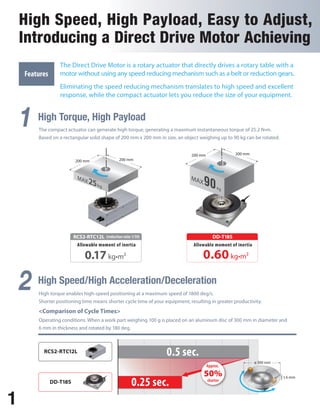
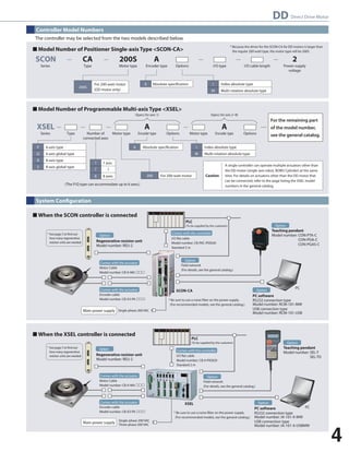
Measuring 180 mm in width, 180 mm in depth and 53 mm in height, the
actuator is fairly compact in size. As it can be installed even in a small
space, you have a greater degree of freedom designing your equipment.
< 70 mm slimmer than the RTC12L type >
70mm 180
4 Index Type or Multi-rotation Absolute Type Can be Selected
The Direct Drive Motor comes in the index type having an
operating range of 0 to 359.999 deg and the multi-rotation
absolute type having an operating range of ±9999 deg.
Neither type requires a home return, meaning that once
the power has been turned on, the actuator can move
directly from the current position. The index type does not
need an absolute battery.
5 Positioner or Program Type Controller Can be Selected
The controller can be selected from [A] positioner type:
dedicated to 1-axis, easy operation and affordable price,
and [B] program type: operable up to 8-axis.
Please choose according to the configuration or use
application.
Application Examples
180
53
233mm 180mm
RCS2-RTC12L DD-T18S
Range of operation
Home return
Unlimited rotations
Absolute battery
Index type
0 to 359.999 deg
Not required
Yes
Not required
Multi-rotation absolute type
±9999 deg
Not required
No
Required
2
and Compact!
High Cost Performance.
Index table
<Small board inspection system>
Positioner type <SCON-CA> Program type <XSEL>
Work part transfer
<Transfer of parts from conveyor to conveyor>
Multi-rotation operation
<Transfer of electronic components>](https://image.slidesharecdn.com/iaiddmotorcj0199-1a-ust-1-1013-141008205348-conversion-gate02/85/Iai-dd-motor-cj0199-1_a-ust-1-1013-3-320.jpg)
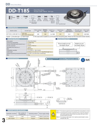
![Conditions for Selection
The following should be checked to determine whether the DD motor can be used to suit the specic conditions required by the customer:
The customer should conrm that the following three points under actual use do not exceed their maximum allowable levels as specied for the DD motor.
Is the total load of device(s) mounted on the actuator no more than 3,400 N?
Is the total load moment of device(s) mounted on the actuator no more than 80 N•m?
Is the load inertia of device(s) mounted on the actuator no more than 0.6 kg•m2?
[1] Thrust load
[2] Load moment applied
[3] Load inertia
To calculate the load conditions, calculate the load inertia of device(s) mounted on the actuator and check the details with the DD motor
selection software. The equations used to calculate the load inertia of typical shapes are shown below for reference purposes.
Download the DD motor selection software from: http://www.iai-robot.co.jp/download/index.html
*** The English version software coming soon ***
J = M x R^2 + 1/8 x M x D^2
Weight: M
Center of rotation
D
R
J = MxR^2+1/12xMx (a^2 + b^2 )
J = 1/8 x M x D^2
D
Center of
rotation
J = 1/12 x M x ( a^2 + b^2 )
Weight: M
a
b
Center of
rotation
Weight: M
Center of rotation
a
b
R
Weight: M
Check the distance, speed, acceleration, deceleration, stop time and other conditions in actual operation against the DD motor specications to
determine whether the DD motor can be used under the applicable operating conditions.
To calculate operating conditions, use the DD motor selection software.
Download the DD motor selection software from: http://www.iai-robot.co.jp/download/index.html
*** The English version software coming soon ***
1 Check Load Conditions
2 Check Operating Conditions
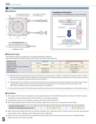
3 Maximum Acceleration/Deceleration Rate and Travel Time Guide
The maximum acceleration/deceleration rate is determined by the load inertia. See the table below to check the maximum acceleration/deceleration rate.
The travel time data is also provided as a guide in the table below. * The data in the table is only intended as a guide, so the travel time is not guaranteed.
Load inertia lower limit [kg•m^2]
Load inertia upper limit [kg•m^2]
45° travel time [sec.]
90° travel time [sec.]
180° travel time [sec.]
270° travel time [sec.]
0
0.005
0.09
0.12
0.17
0.22
0.005
0.01
0.10
0.12
0.17
0.22
0.01
0.02
0.11
0.14
0.19
0.24
0.02
0.03
0.12
0.16
0.21
0.26
0.03
0.04
0.13
0.17
0.23
0.27
0.04
0.05
0.14
0.18
0.24
0.29
0.05
0.06
0.15
0.20
0.27
0.32
0.06
0.07
0.17
0.22
0.29
0.35
0.07
0.08
0.19
0.24
0.32
0.38
0.08
0.09
0.21
0.26
0.35
0.41
0.09
0.1
0.23
0.29
0.37
0.44
0.1
0.2
0.39
0.48
0.60
0.69
0.2
0.3
0.62
0.73
0.89
1.00
0.3
0.4
0.70
0.83
1.01
1.14
0.4
0.5
0.87
1.02
1.22
1.36
0.5
0.6
1.11
1.23
1.42
1.68
(Note) The time listed in the above table is the duration from the reception of a travel command till convergence within the positioning band of 0.028 degrees (approximately 100 arcseconds).
6
DD Direct Drive Motor](https://image.slidesharecdn.com/iaiddmotorcj0199-1a-ust-1-1013-141008205348-conversion-gate02/85/Iai-dd-motor-cj0199-1_a-ust-1-1013-7-320.jpg)


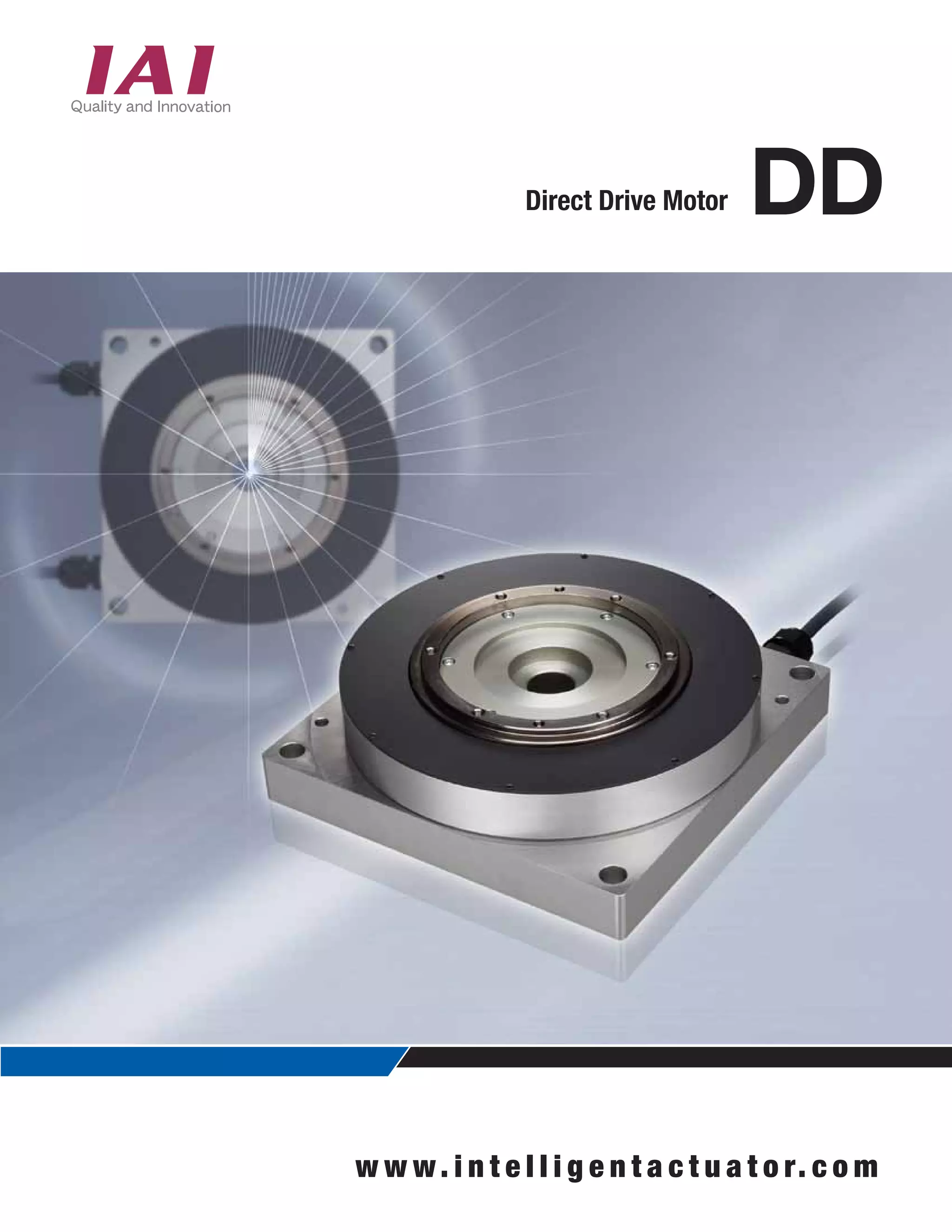
The document provides information about the Direct Drive Motor DD, a rotary actuator that directly drives a rotary table with a motor without using any speed reducing mechanisms. Some key details include: - It can generate high torque of up to 25.2 Nm and rotate loads of up to 90 kg. This allows for higher speeds, better response time, and a more compact design than actuators with speed reducers. - It comes in either an index type with a range of 0-359.999 degrees or a multi-rotation absolute type with a range of ±9999 degrees. - Controllers and accessories that can be used with it include the SCON-CA single-axis controller and XSEL


![Getting Started with Apache Spark: Big Data Made Simple [Free Meetup]](https://cdn.slidesharecdn.com/ss_thumbnails/apachesparkgettingstarted-260203175547-8361bcc3-thumbnail.jpg?width=640&height=640&fit=bounds)


