Download to read offline
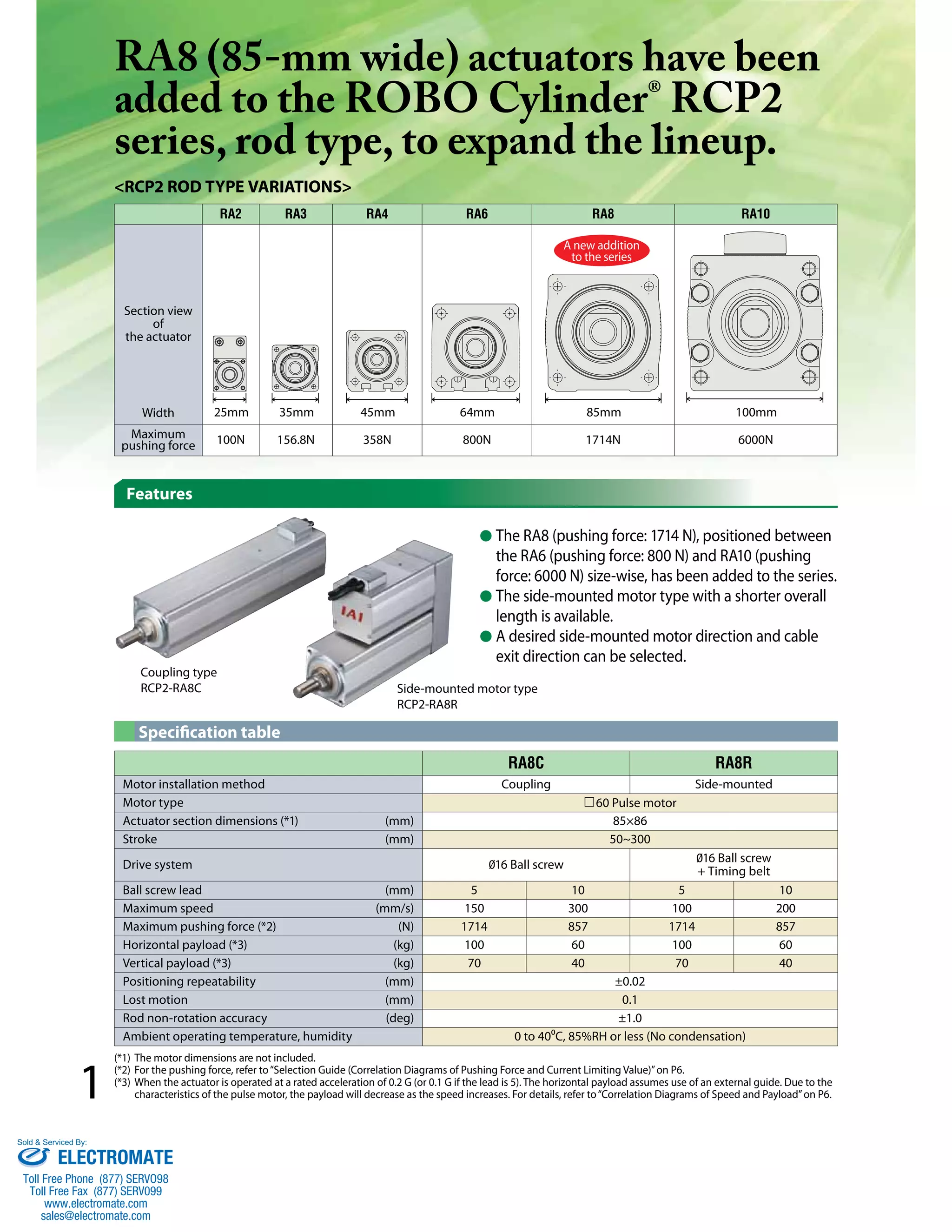
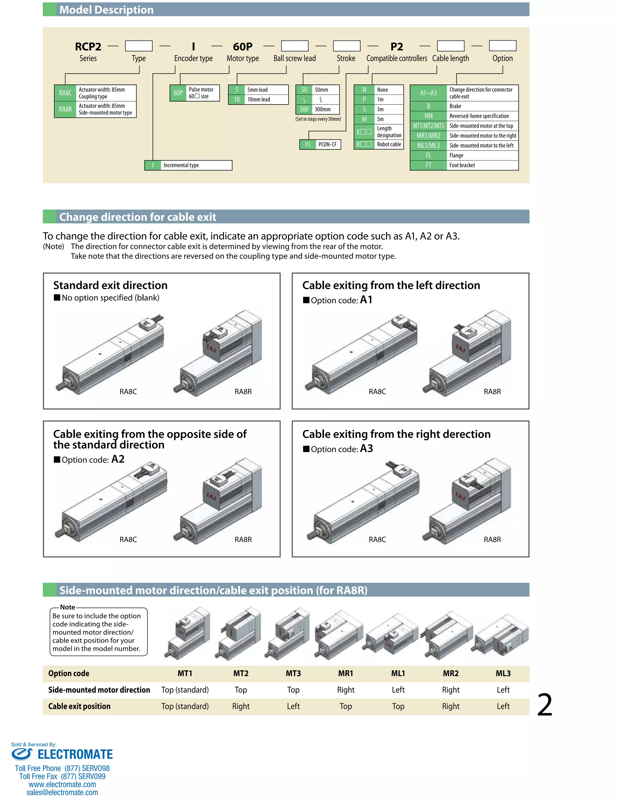
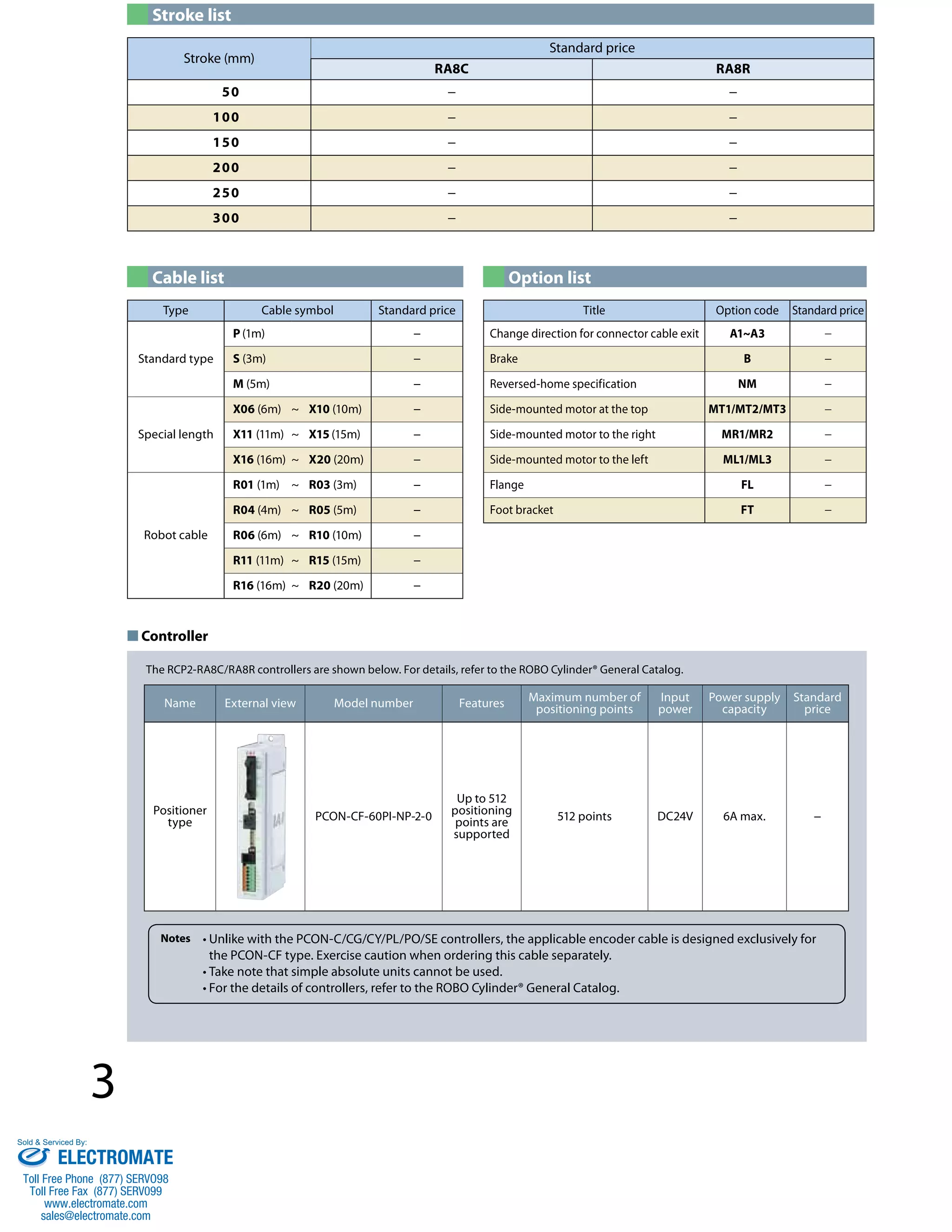
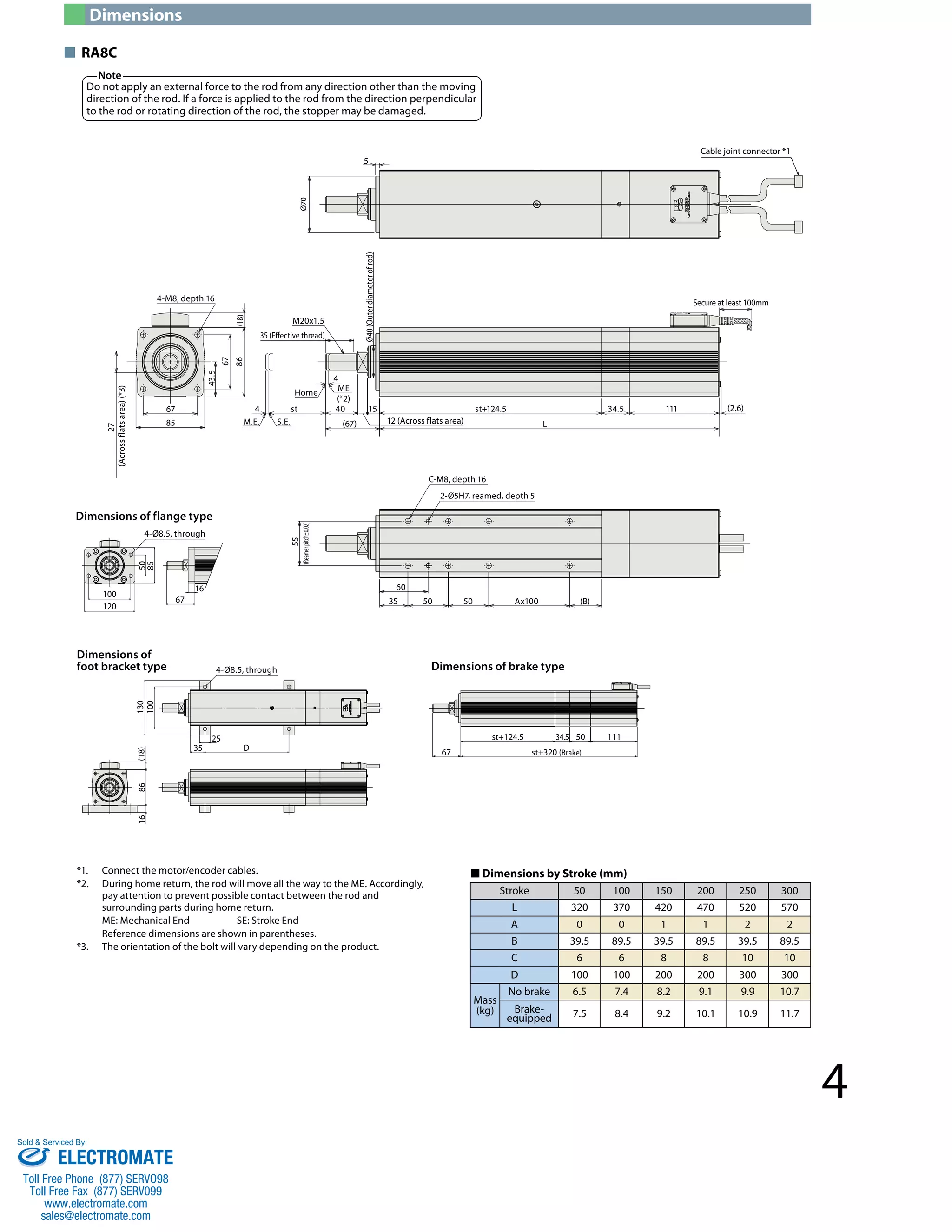
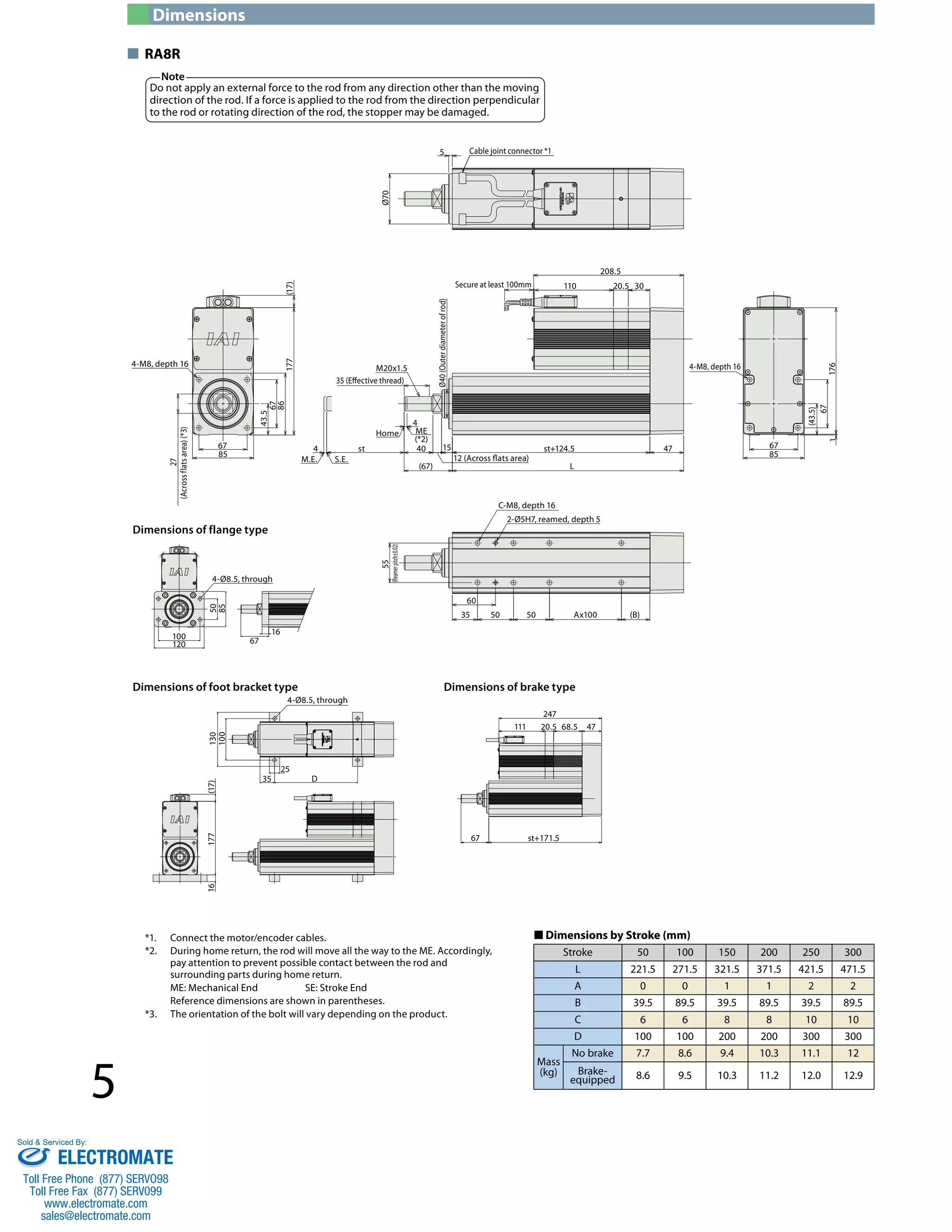
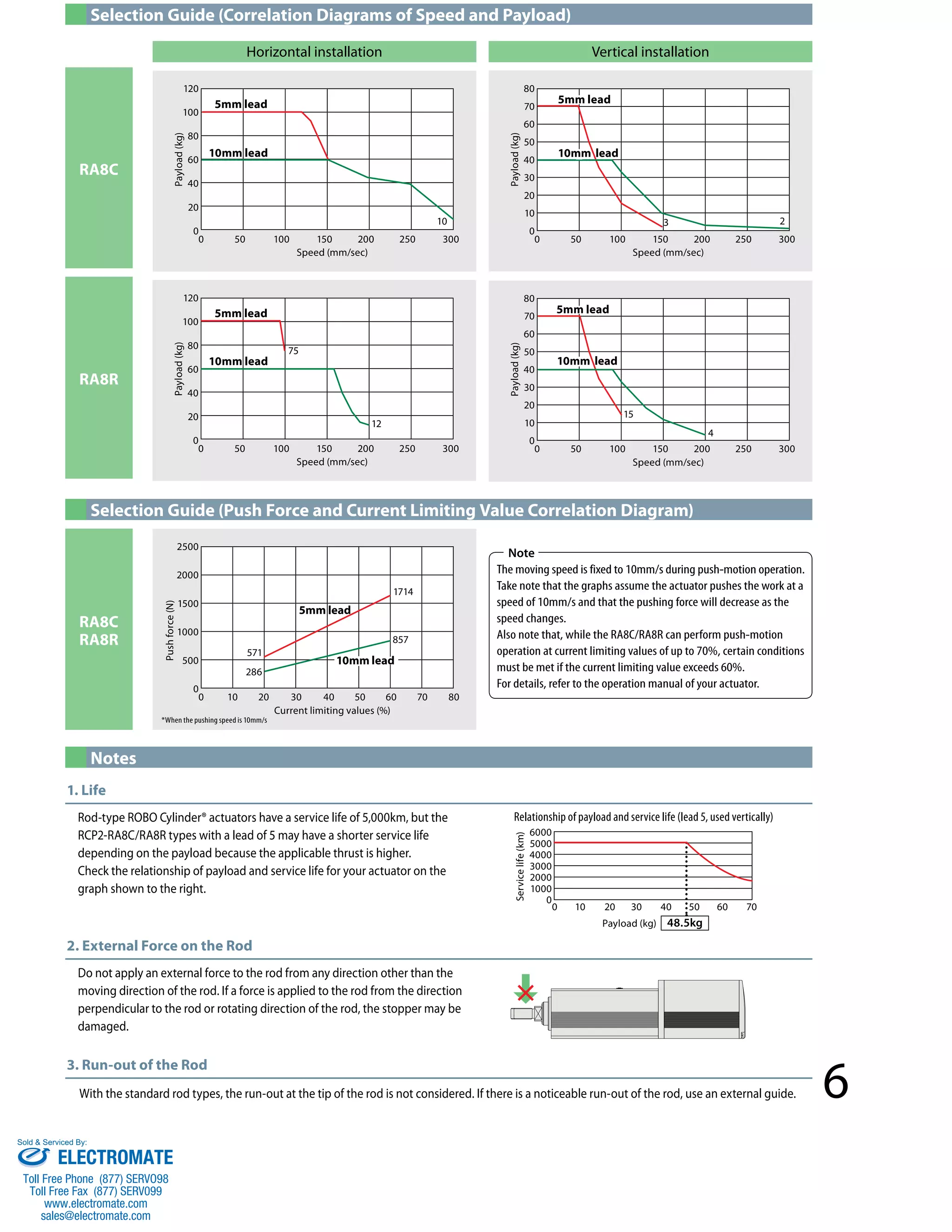

- The document describes the ROBO Cylinder RCP2-RA8C/RA8R rod type actuators, which have an 85mm width. - A new RA8 size has been added to the RCP2 series to expand the lineup, with a pushing force of 1714N. - The document provides details on specifications, dimensions, controller options and selection guides for determining push force and payload based on speed.


