Download to read offline
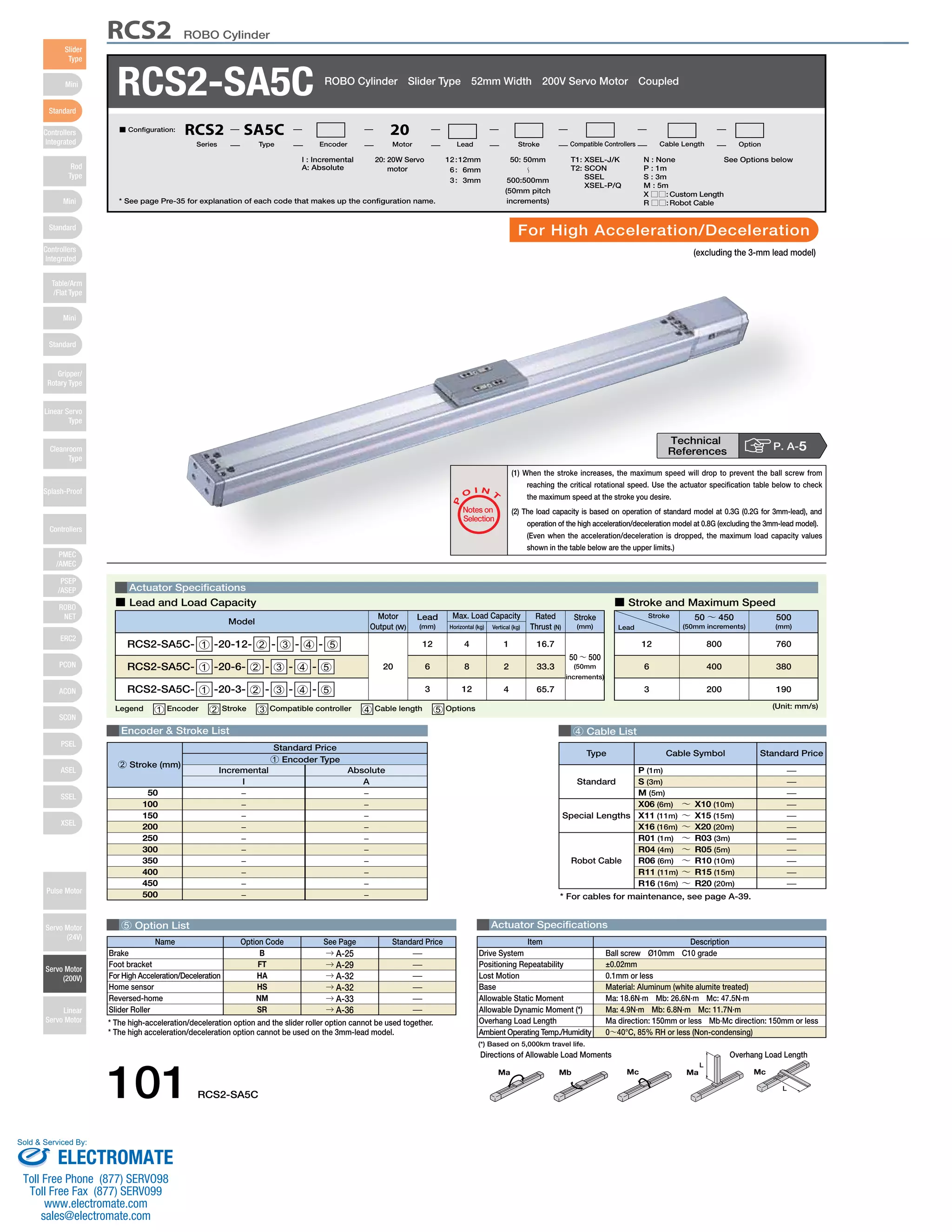
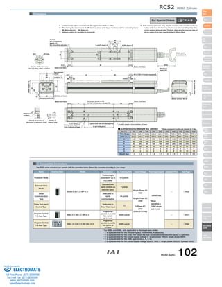

RCS2 ROBO Cylinder specifications including: 1) Maximum load capacity is based on operation at 0.3G acceleration for standard models and 0.8G for high acceleration/deceleration models. 2) Stroke lengths range from 50mm to 500mm in 50mm increments, with maximum speeds varying depending on stroke. 3) Compatible controllers include SCON, SSEL, and XSEL models for positioning, programming, and serial communication.


