Downloaded 38 times
![Hydrostatic Continuous Variable Power Transmission Drive for Two wheelers Using Radial Piston Pump and Motor Set - A Technical Review
(IJSRD/Vol. 1/Issue 3/2013/0079)
All rights reserved by www.ijsrd.com
711
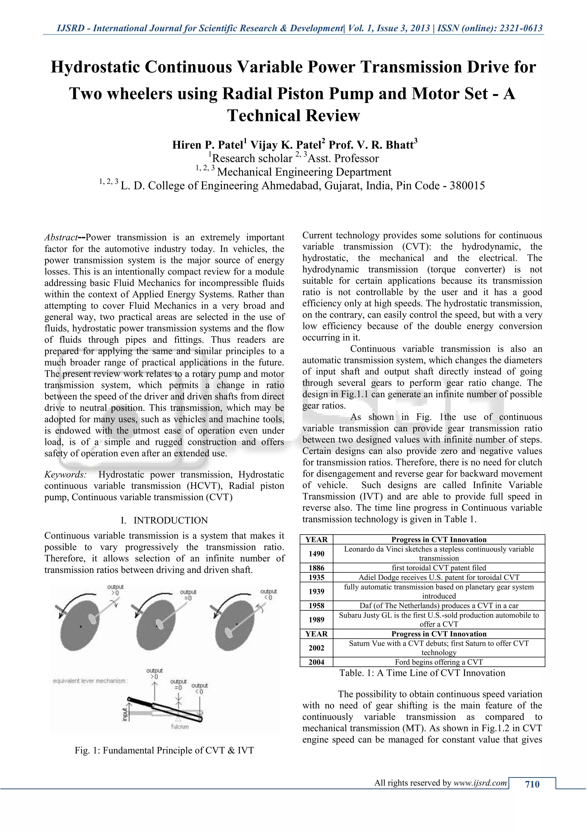
better engine performance, fuel economy, reduced wear of
engine and less emissions.
Fig .2: Graph for Vehicle speed v/s Engine speed for
Mechanical(Gear) Transmission & CVT.
In hydrostatic continuous variable transmission
(HCVT) (Fig1.3), the input mechanical energy is converted
into hydraulic pressure and flow energy using hydraulic
pump, and the same is converted back into mechanical
energy near the load point using hydraulic motor. For this,
either hydraulic pump or hydraulic motor or both are of
variable flow rate type to change the gear ratio for the
transmission.
Fig. 3: Scheme for Hydrostatic CVT.
Currently off highway use of CVT is in certain agriculture,
road construction and other heavy machines, due to
uninterrupted tractive force from steady state to max speed,
compact design and improved ride comfort. Table.2 lists
main features and benefits of CVT.
Feature Benefit
Step-less gear-change from rest to
cruising speed
Eliminates “shift-shock” making the
ride smoother
Keeps the engine in its optimum
power range
regardless of how fast the car is
travelling
Improved fuel efficiency
Responds better to changing
conditions, such as
changes in throttle and speed
Eliminates gear hunting as a car
decelerates, especially going up a hill
Less power loss in a CVT than a
typical automatic transmission
Better acceleration
Can incorporate automated
versions of mechanical clutches
Replaces inefficient torque
converters
Better control of a gasoline
engine's speed range
Better control over emissions
Table. 2: Features and Benefits of CVT
II. LITERATURE REVIEW
Numbers of research papers and studies have been
conducted on the application of hydrostatic power
transmission in vehicles and its impact on various
parameters like power transmission efficiency, speed and
torque on engine side and load side, percentage slip etc.
Scope for Purely Hydrostatic TransmissionA.
In 1973, James J. Bauer [1]
compared conventional power
trains with available axial piston hydraulic pumps and
motors to provide an opportunity to improve the
productivity, reliability, and serviceability to the designers
of work vehicles in the 15-80 hp sizes. Purely Hydrostatic
Continuous variable transmission with an overall ratio of 6
may be worked out as per R. Maistrelli [2]
. It gives high
power to weight ratio and help to avoid bulk and weight
penalty. Materials and manufacturing processes, which are
not more sophisticated than in conventional automobile
manufacturing, can be used for mass production. Although
lower than in gear transmission, efficiency of the hydrostatic
transmission is suitable for automobile use.
Concepts and Development Trends for Efficiency
Improvement of Hydrostatics in Mobile Applications are
given by Karl-Erik Rydberg et al.[3]
for mobile vehicles such
as earth moving machines, agriculture machines, forest
machines, industrial and mining lifters is important due to
the demand for sophisticated performance, high productivity
and high output capacity combined with high overall
efficiency over a wide velocity range.
Investigation of components of HydrostaticB.
Transmission
S. K. Mandal et al.[4]
have investigates the effects of the
different loss coefficients of the pump and the motor on the
overall performance of the system that may be useful for the
selection of hydrostatic system and its components. The
performance of the system depends on the operating
parameters of the system such as pump speed, load torque
and supply flow rate. The characteristics of various loss
coefficients of pump and motor may be obtained
experimentally. Using them for given load torque and pump
speed, the efficiency of the hydrostatic drives can be
predicted.
Fig. 3: Drawing of multi stroke radial piston motor
Fig.3 shows the general constructional feature of a multi
stroke radial piston hydrostatic motor [5]
. The motor consists
of two-part housing (1) and (2), rotary piston (3), rotor
assembly (4), cam plate (5), output flange (6), control](https://image.slidesharecdn.com/ijsrdv1i3079-140801081545-phpapp01/75/Hydrostatic-Continuous-Variable-Power-Transmission-Drive-for-Two-wheelers-using-Radial-Piston-Pump-and-Motor-Set-A-Technical-Review-2-2048.jpg)
![Hydrostatic Continuous Variable Power Transmission Drive for Two wheelers Using Radial Piston Pump and Motor Set - A Technical Review
(IJSRD/Vol. 1/Issue 3/2013/0079)
All rights reserved by www.ijsrd.com
712
section (7), roller bearing (8), inlet port (A), outlet port (B),
drain port (L) and annular passages (D). There are eight
pistons, which are radially placed with equal angular spaced
in the rotor and is supported on the cam plate by way of
rollers. The rotor is connected to the output shaft flange by
means of a spline. The output flange is mounted on the shaft
over a set of taper roller bearings. Similarly, the cylinder
assembly is also kept over a set of taper roller bearings. The
two parts of the motor were fastened with the help of bolts.
The annular passages (D) are connected with the cylinder
inlet and outlet ports by way of axial holes. A case drain
port(L) is provided to accommodate internal leakage.
The article by S. K. Mandal et al.[4]
analyzed the
overall performance of an open circuit hydrostatic drive as a
function of pump speed and load torque taking into account
the various loss coefficients of the components of the system
as shown in Fig.4. The analysis has been carried out to
investigate the effects of the operating parameters of the
pump and the motor on the overall efficiency of the system.
In the article by K. Dasgupta et al.[6]
dynamic analysis of an
open-circuit hydrostatic (HST) drive has been carried out to
study its performance. A Low Speed High Torque (LSHT)
radial piston motor has been considered for the drive. Bond
graph simulation technique is used to model the hydrostatic
drive. The relationships of the loss coefficients of the drive
with the other system variables, obtained from the steady-
state model, are identified through experimental
investigation. Using the parametric values, the overall
dynamic model of the hydrostatic drive has been validated
experimentally.
Fig. 4: Overall efficiency versus pump speed
Tribology in Hydrostatic Transmission componentsC.
A tribological interface is composed of two contacting
surfaces in relative motion as per Fig. 5. The radial piston
hydraulic pump and motor includes many tribological
interfaces. The interfaces are made up of the contacts
between the moving parts in the pump and motor that
transform energy in the form of motion of input shaft into
hydraulic flow and again hydraulic flow into motion of the
output shaft. Many of them are highly loaded due to the
large forces those must be transmitted to produce the
required torque.
Fig. 5: Forces in Piston Assembly.
Minimizing the losses/friction in the tribological
interfaces leads to less energy needed to produce the desired
motion. Another aspect of tribology is wear in the interfaces,
which can affect durability or toughness of the pump and
motor.
The effects of the friction within the cylinder bore,
the dynamics of the piston, and the centrifugal force of the
piston–slipper assembly are examined by S.L. Nie et al.[7]
.
The characteristic equation of the hydrostatic slipper bearing
with an annular orifice damper is formulated, where the
effects of various geometric parameters Fig. 6 (e.g. damping
length, supporting length, and clearance between the piston
and the cylinder bore) are reflected.
Fig. 6: Forces Analysis on a Piston
The friction coefficient, the inertia and centrifugal
loads due to the high rotating speed of the motor have
significant influences on the reaction force.
Patents reviewed for Purely Hydrostatic TransmissionD.
Einar Samuelsson, Sweden, US Patent No. 4,522,110, June.
11, 1985 [8]
, has invented the radial piston motor with a cam
disc and a cylinder block with a number of pistons running
in cylinders in the block presses rollers against the cam disc
in such a way that a torsional moment arises. As shown in
Fig. 7 and Fig. 8, The rollers are formed with guide
members running in slots in guide units, which take up
tangential force. The rollers are mounted in roller cages,
which are formed with hydrostatic bearings. At the outer
end each piston is formed with a part – spherical bearing
surface and the roller cage has a cooperating part spherical](https://image.slidesharecdn.com/ijsrdv1i3079-140801081545-phpapp01/75/Hydrostatic-Continuous-Variable-Power-Transmission-Drive-for-Two-wheelers-using-Radial-Piston-Pump-and-Motor-Set-A-Technical-Review-3-2048.jpg)
![Hydrostatic Continuous Variable Power Transmission Drive for Two wheelers Using Radial Piston Pump and Motor Set - A Technical Review
(IJSRD/Vol. 1/Issue 3/2013/0079)
All rights reserved by www.ijsrd.com
713
bearing surface, which allows angular movement between
the roller cages and the pistons in all directions.
Fig. 7: Exploded Drawing of Radial Piston Motor (US
Patent No 4,522,110)
Fig. 8: Drawing of Radial Piston Motor (US Patent No
4,522,110)
Ray M. Hauser et al., Sullivan Ill, US Patent No. 5,314,387,
May. 24, 1994 [9]
, have invented an improved hydrostatic
transmission (Fig. 9) which is compact, reliable and
economical to manufacture, including a novel means for
reducing the speed of the input to the transaxle using both
hydraulics and mechanical gearing; an improved differential
which is stronger and less complicated than prior art
designs; a more effective and efficient means for braking the
transaxle, an improved means for hydraulically bypassing
the hydrostatic transmission and a unique check valve
arrangement for maintaining oil pressure within the
hydrostatic transmission.
Fig. 9: Design of CVT at differential (US Patent No.
5,314,387)
Dimosthenis Valsamis, Greece, US Patent No. 5,799,487,
Sep.1, 1998 [10]
, had suggested an automatic hydrostatic
transmission in which two vane pumps have their pumping
chambers are coupled together as per Fig. 10 in a closed
circuit with a constant volume of hydraulic fluid, the volume
of each pump being changed by the axial displacement of a
moving side of the chamber and the respective rotor towards
and away from a diaphragm through which the vanes can
extend so that either pump can act as the displacement
inducer or as the driven member. One of the rotor has a nut
provided on a large pitch screw for automatic adjustment of
the pump chamber volume in accordance with load
conditions while the other moving side assembly has a key
and keyway connection to its shaft.
Fig. 10: Hydrostatic CVT using Vane Type Pump-Motor set
(US Patent No. 5,799,487)
Yoshida et al. Tokyo, US Patent No. 7,146,811 B2, Dec. 12,
2006 [11]
, have developed the hydrostatic continuous variable
transmission specially for motor bike (Fig. 11 and Fig. 12)
in which hydraulic pump and a hydraulic motor are
connected through a hydraulic closed circuit and the](https://image.slidesharecdn.com/ijsrdv1i3079-140801081545-phpapp01/75/Hydrostatic-Continuous-Variable-Power-Transmission-Drive-for-Two-wheelers-using-Radial-Piston-Pump-and-Motor-Set-A-Technical-Review-4-2048.jpg)
![Hydrostatic Continuous Variable Power Transmission Drive for Two wheelers Using Radial Piston Pump and Motor Set - A Technical Review
(IJSRD/Vol. 1/Issue 3/2013/0079)
All rights reserved by www.ijsrd.com
714
capacity of the hydraulic motor is varied to vary the speed
continuously.
Fig. 11: Hydrostatic CVT Developed for Bike by Honda
Motor Co. Ltd
Fig. 12: Bike with hydrostatic CVT
III. CASE STUDY
There are few Hydrostatic CVT available for off road
vehicles like Spicer® 318,by Dana Spicer, Italy [12]
for off
highway vehicles and ZF Driveline and chassis
Technologies.
Fig. 13: Spicer® 318, Hydrostatic CVT by Dana Spicer
Dana Spicer had Designed Hydrostatic CVT (Fig. 13) for
compact front-end loaders and medium-sized telescopic
boom handlers, the Spicer® 318 hydrostatic continuously
variable transmission offers full CVT functionality without
torque interruption, and increased efficiency at high travel
speeds of more than 20 percent over standard hydrostatic
transmissions. The possibility to obtain continuous speed
variation with no need of gear shifting is the main feature of
the Spicer Model 318 hydrostatic continuously variable
transmission. This gearbox is specifically designed for
hydrostatically driven industrial vehicles, which require
maximized top speed, efficiency, and tractive effort. It can
accommodate various combinations of hydraulic motors
from 55 cc up to 115 cc. The second motor can be
disconnected at high speed and re-engaged when high
torque is needed. The high efficiency of the system reduces
power loss and consequently the fuel consumption of the
vehicle.
The hydrostatic continuously variable transmission,
HydrostarHC85[13]
(Fig. 14), facilitates Precise maneuvering
of compact loaders at full tractive power over the whole
speed range. An important constituent are two crankshaft
radial-piston motors. Due to their integration into the
transmission system, the interfaces to the vehicle have been
reduced. The transmission can be directly mounted onto the
ZF axle or separately in the chassis.
Fig. 14: Hydrostar HC 85 by ZF Technologies
Advantages of Hydrostar HC 85A.
Driving speeds up to 50 km/h
Improved ride comfort due to continuously variable
shifting
No interruption of tractive force, giving improved
operational performance
More design freedom in vehicle construction due to
compact design
The integration of the hydraulic motors into the
transmission system reduces the number of external
hose lines and valves, so that interfaces to the vehicle
are reduced.
Low moving-off speed due to electronic traction drive
control.
Low noise emissions due to low hydraulic motor speeds
Low fuel consumption, increased efficiency
IV. OUTCOME OF TECHNICAL REVIEW
Due to uninterrupted tractive force from steady state to max
speed, compact design and improved ride comfort,
hydrostatic continuous variable transmission drive may be
effective and advantageous in many off highway vehicles,
certain agricultural vehicles, in road construction work and
other heavy machines.
It can be revealed that the hydrostatic CVT are very
common in heavy duty off-highway vehicles and machines,](https://image.slidesharecdn.com/ijsrdv1i3079-140801081545-phpapp01/75/Hydrostatic-Continuous-Variable-Power-Transmission-Drive-for-Two-wheelers-using-Radial-Piston-Pump-and-Motor-Set-A-Technical-Review-5-2048.jpg)
![Hydrostatic Continuous Variable Power Transmission Drive for Two wheelers Using Radial Piston Pump and Motor Set - A Technical Review
(IJSRD/Vol. 1/Issue 3/2013/0079)
All rights reserved by www.ijsrd.com
715
but not popular for on-highway vehicles. There are certain
efforts in the direction of hydrostatic CVT applications in
small vehicles. But still none had used radial piston pump
for that. So some research work can be done in the direction
of using radial piston pump and motor set for designing
hydrostatic CVT for small capacity vehicles.
REFERENCES
[1] Bauer, J., "Application of Hydrostatic Transmissions to
Small and Medium Horsepower Vehicles," SAE
Technical Paper 730786, 1973, doi:10.4271/730786
[2] R. Maistrelli, “Purely Hydrostatic High Ratio
Transmission”, SAE Technical Paper 790042, 1979,
doi: 10.4271/790042
[3] Karl-Erik Rydberg, et al,” Concepts and Development
Trends for Efficiency Improvement of Hydrostatics in
Mobile Applications”, SAE Technical Paper 2002-01-
1422, doi 10.4271/2002-01-1422
[4] S. K. Mandal et al,” Performance Investigation of
Hydrostatic Transmission System as a Function of
Pump Speed and Load Torque”, J. Inst. Eng. India Ser.
C (Springer) (April–June 2012) 93(2):187–193 doi
10.1007/s40032-012-0022-4
[5] Bosch Rexroth India Ltd, Product Catalogue: RE 15
205/05.93, Hydraulic Motor MCR3F280F 180Z32B2M
Technical Information (Bosch Rexroth India Ltd,
Vatva, 2012)
[6] K. Dasgupta et al.,” Dynamic analysis of a low speed
high torque hydrostatic drive using steady-state chara-
cteristics”, Mechanism and Machine Theory 52 (2012)
1–17 doi:10.1016/j.mechmachtheory.2011.12.004
[7] S.L. Nie et al., “Tribological study on hydrostatic
slipper bearing with annular orifice damper for water
hydraulic axial piston motor”, Tribology International
39(2006)1342–1354 doi:10.1016/j.triboint 2005.10.007
[8] Einar Samuelsson, Sweden, US Patent No. 4,522,110,
June. 11, 1985.
[9] Ray M. Hauser et al., Sullivan Ill, US Patent No.
5,314,387, May. 24, 1994.
[10]Dimosthenis Valsamis, Greece, US Patent No.
5,799,487, Sep. 1, 1998.
[11]Yoshida et al., Tokyo, US Patent No. 7,146,811 B2,
Dec. 12, 2006.
[12]DANA SPICER off-Highway Systems Catalogue,Italy-
38092 www.dana.com/offhighway.
[13]ZF Friedrichshafen AG, Germany. ZF Technology in
Construction
Vehicles.http://www.zf.com/corporate/en/products/prod
uct_range/construction_vehicles/construction_machiner
y_compact_loader_hydrostar_hc_85.shtml
](https://image.slidesharecdn.com/ijsrdv1i3079-140801081545-phpapp01/75/Hydrostatic-Continuous-Variable-Power-Transmission-Drive-for-Two-wheelers-using-Radial-Piston-Pump-and-Motor-Set-A-Technical-Review-6-2048.jpg)

The document reviews the hydrostatic continuous variable power transmission (HCVT) systems for two-wheelers using radial piston pumps and motors, highlighting their efficiency and operational benefits in automotive and heavy machinery applications. It discusses the evolution of continuous variable transmission technology, emphasizing the advantages of HCVT such as smooth operation, improved fuel efficiency, and reduced need for gear shifting. The analysis of relevant literature and patents underscores the relevance of hydrostatic transmission in enhancing the performance of vehicles in various operational contexts.