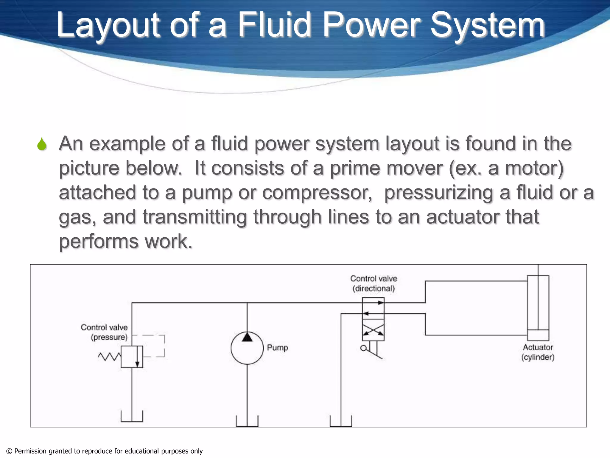
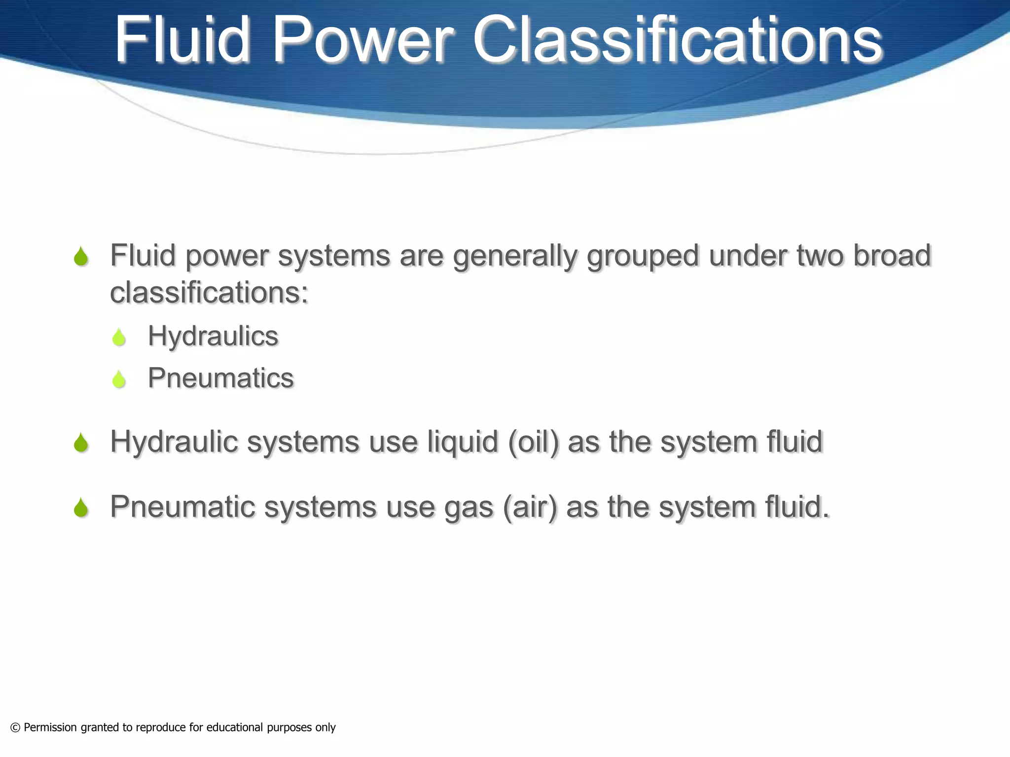
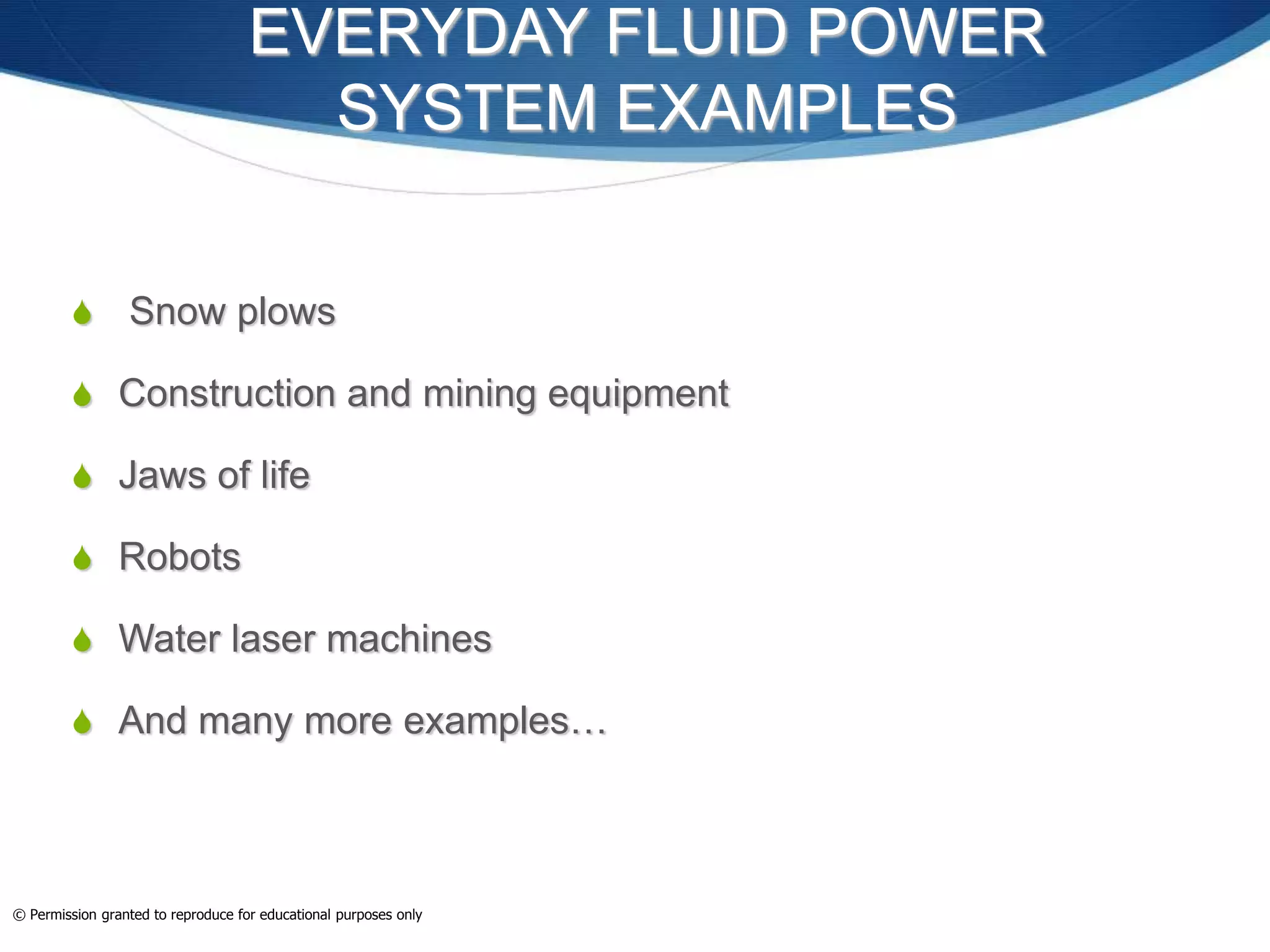
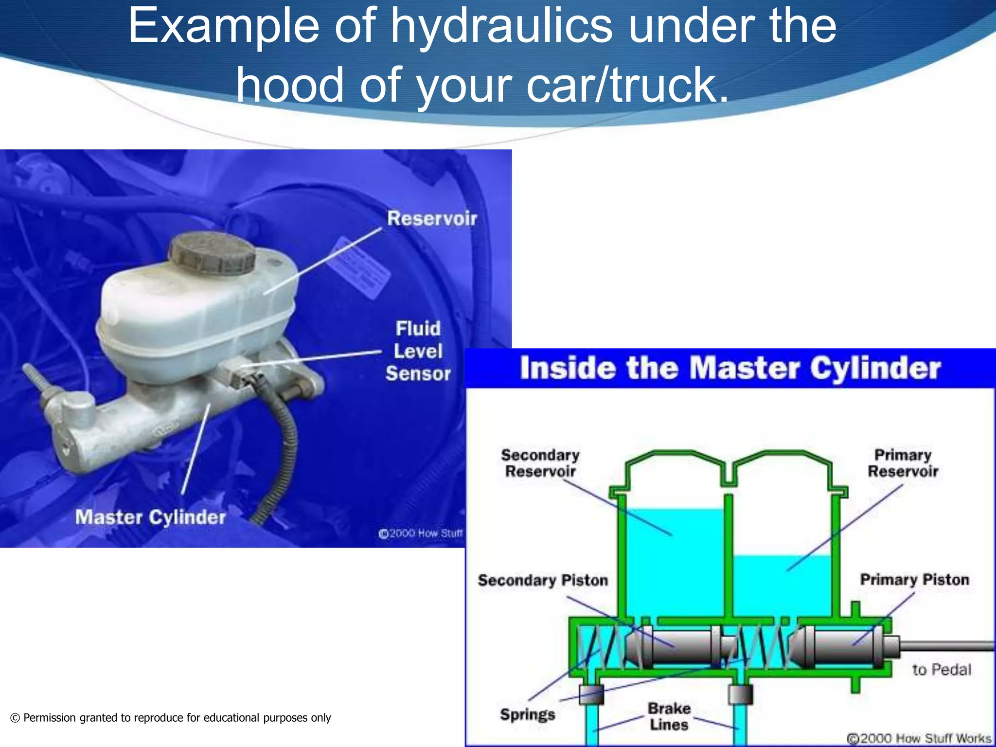
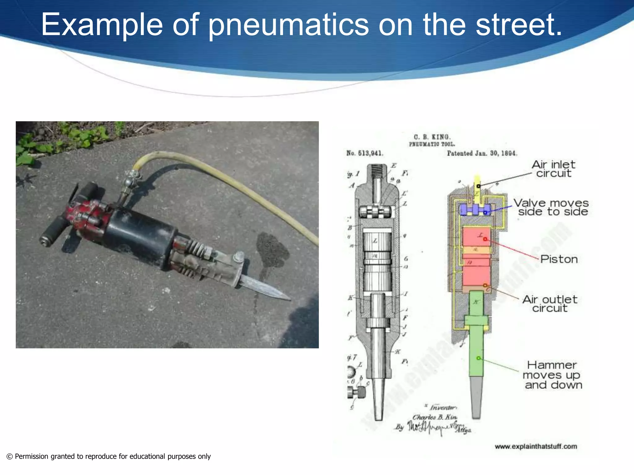
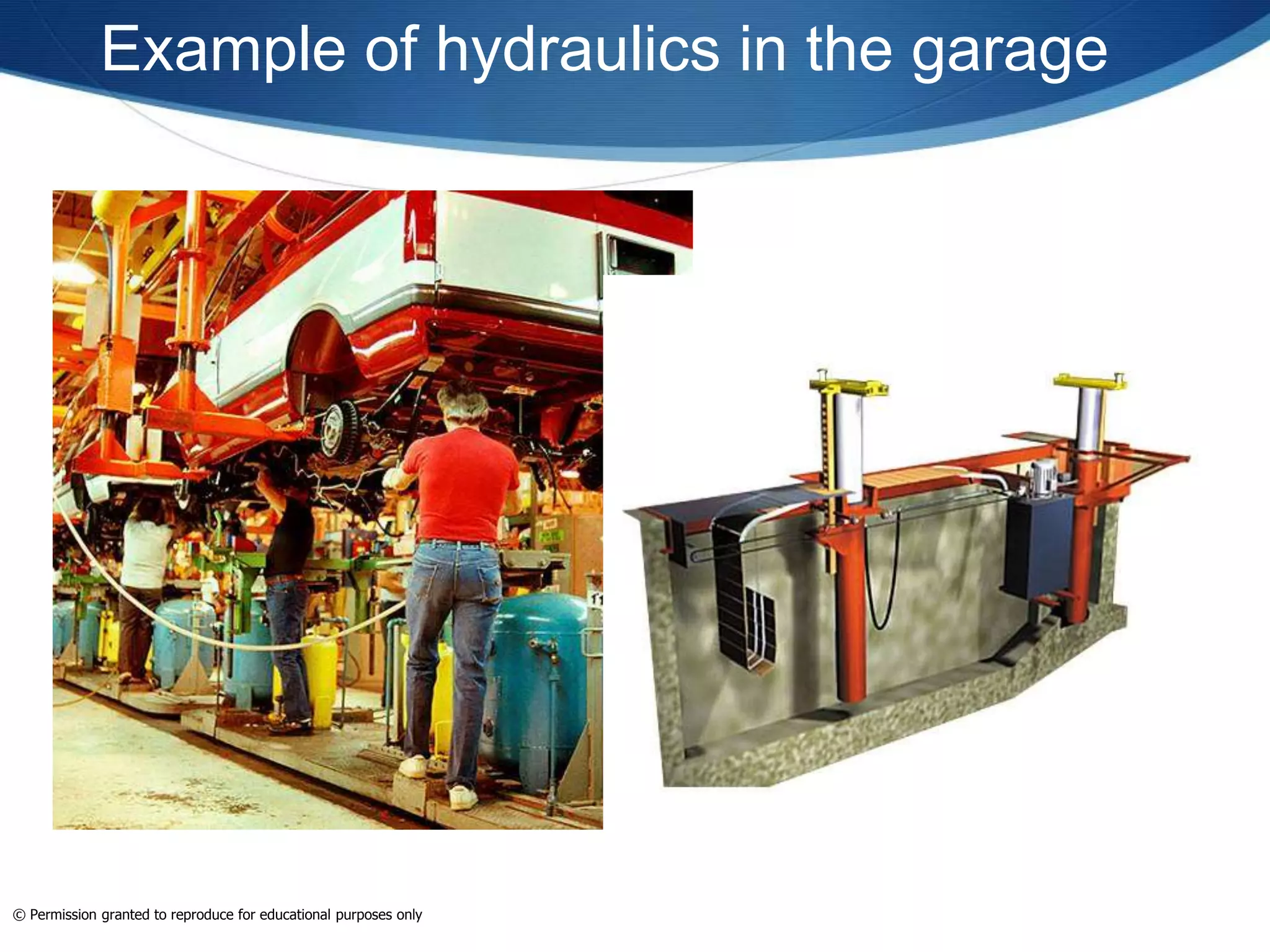
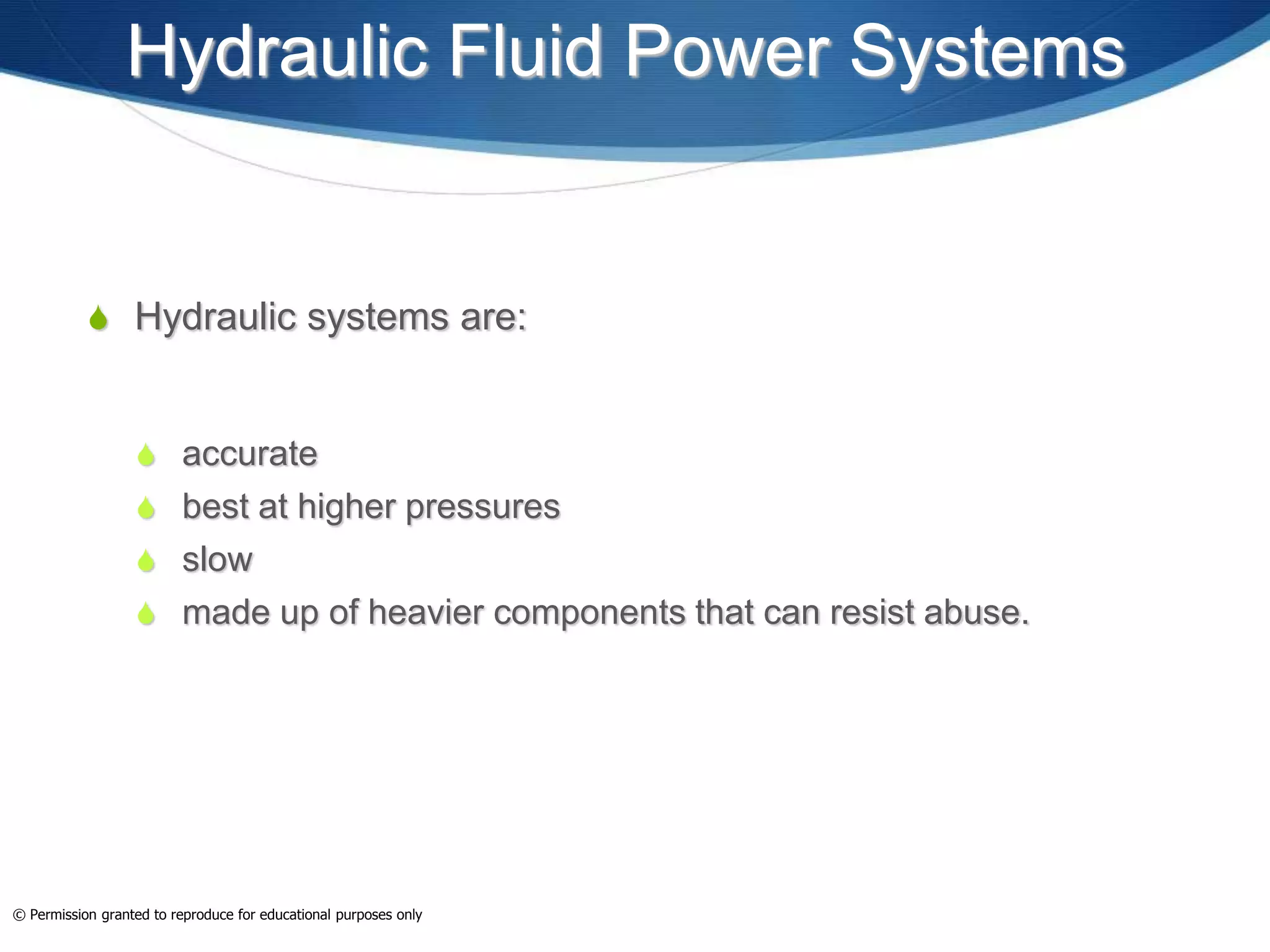
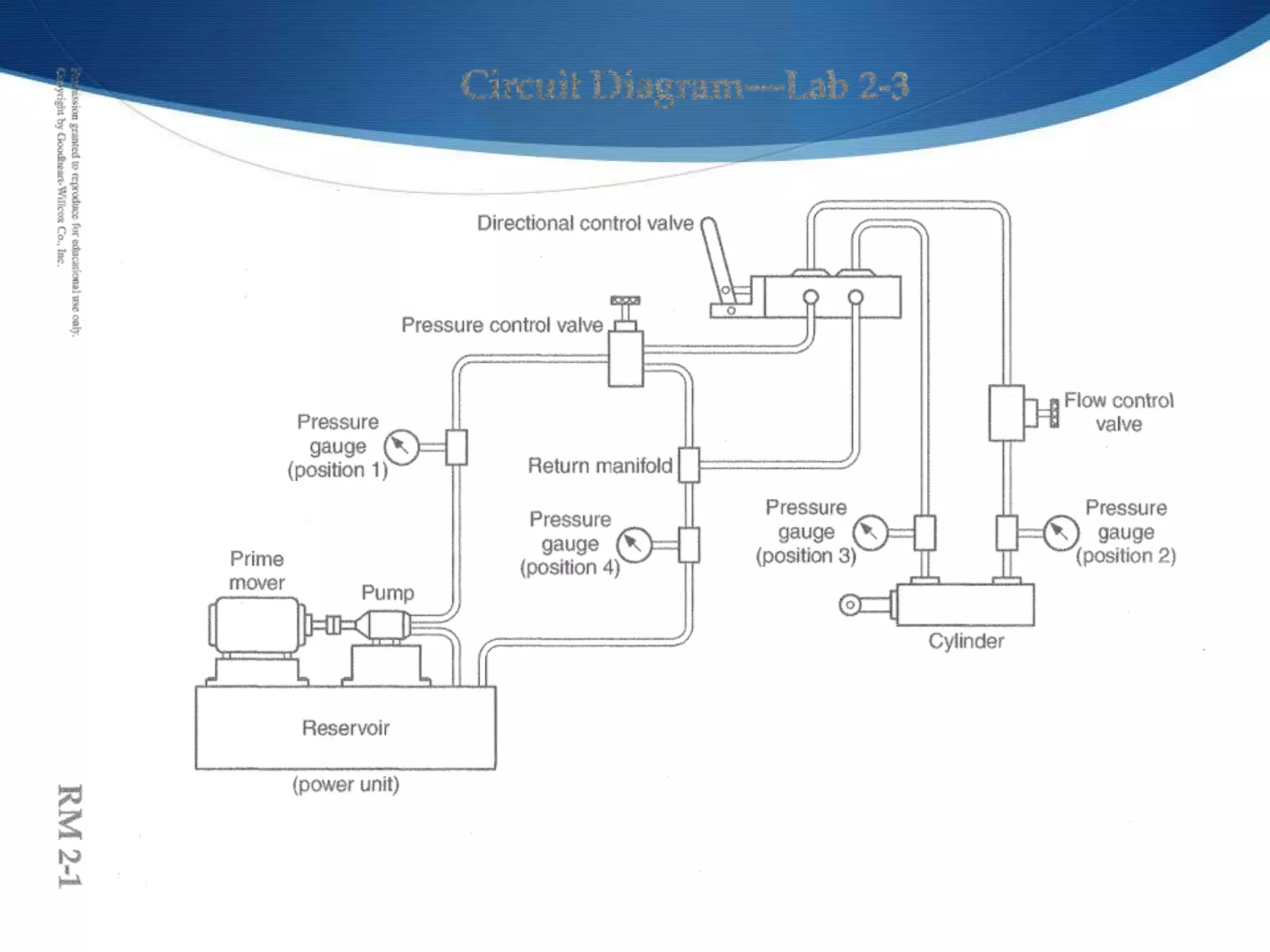
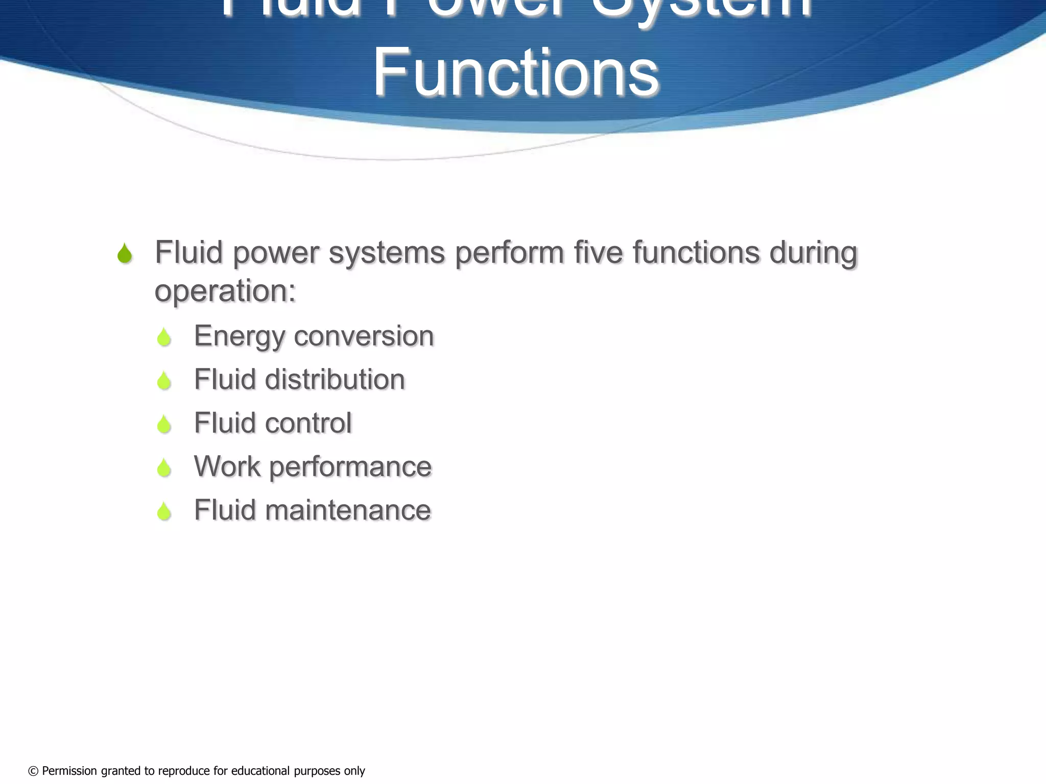
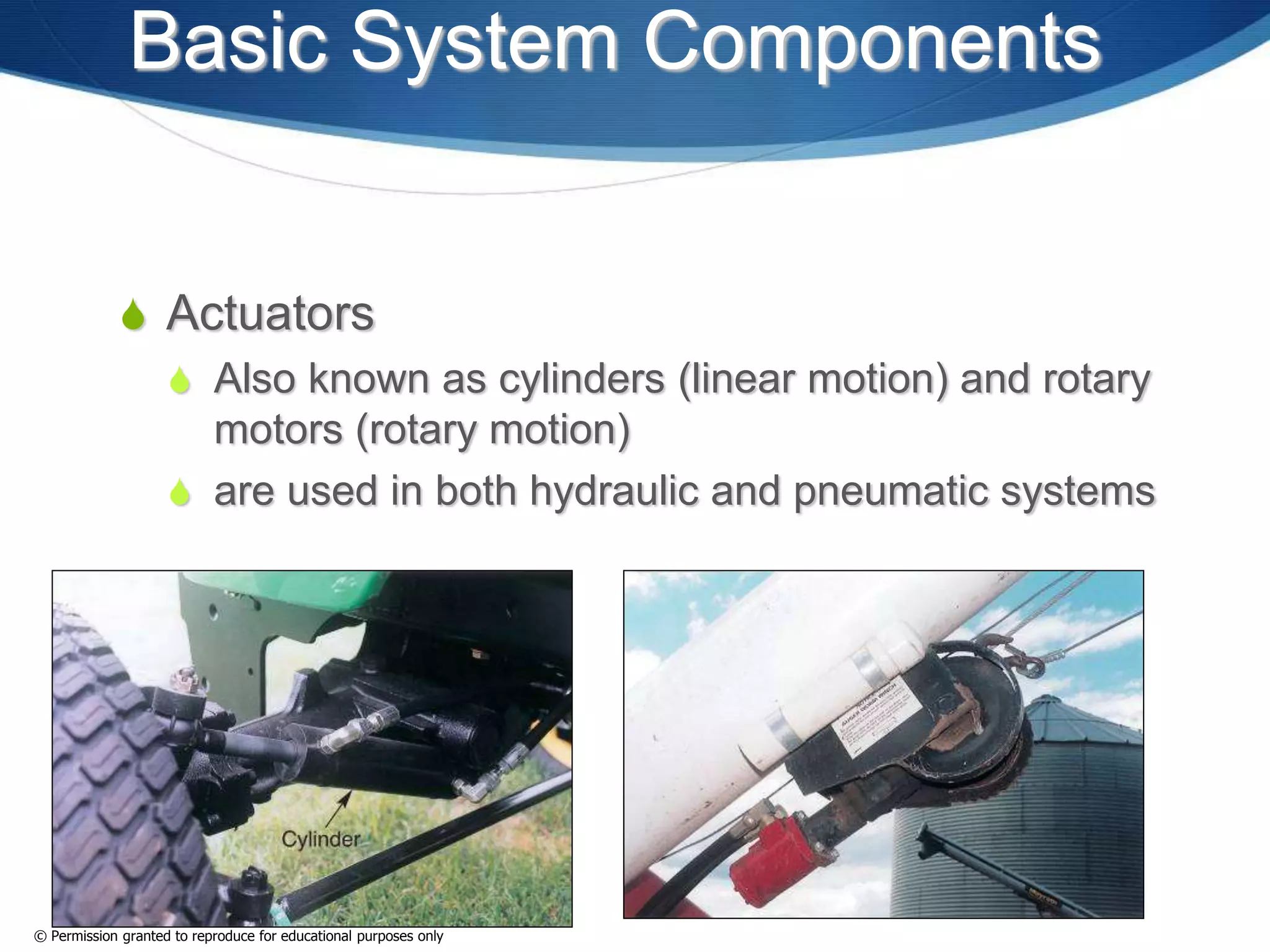
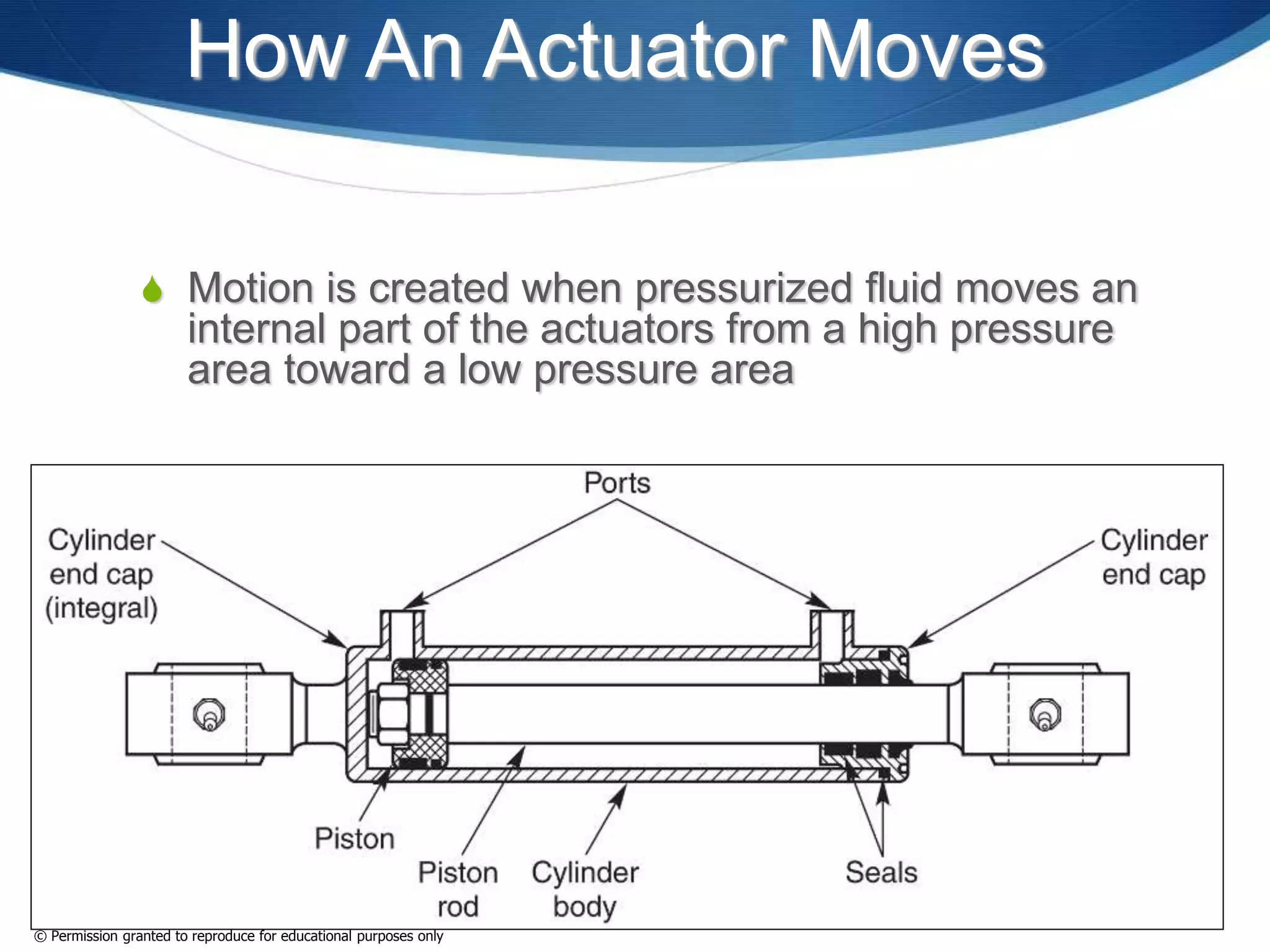
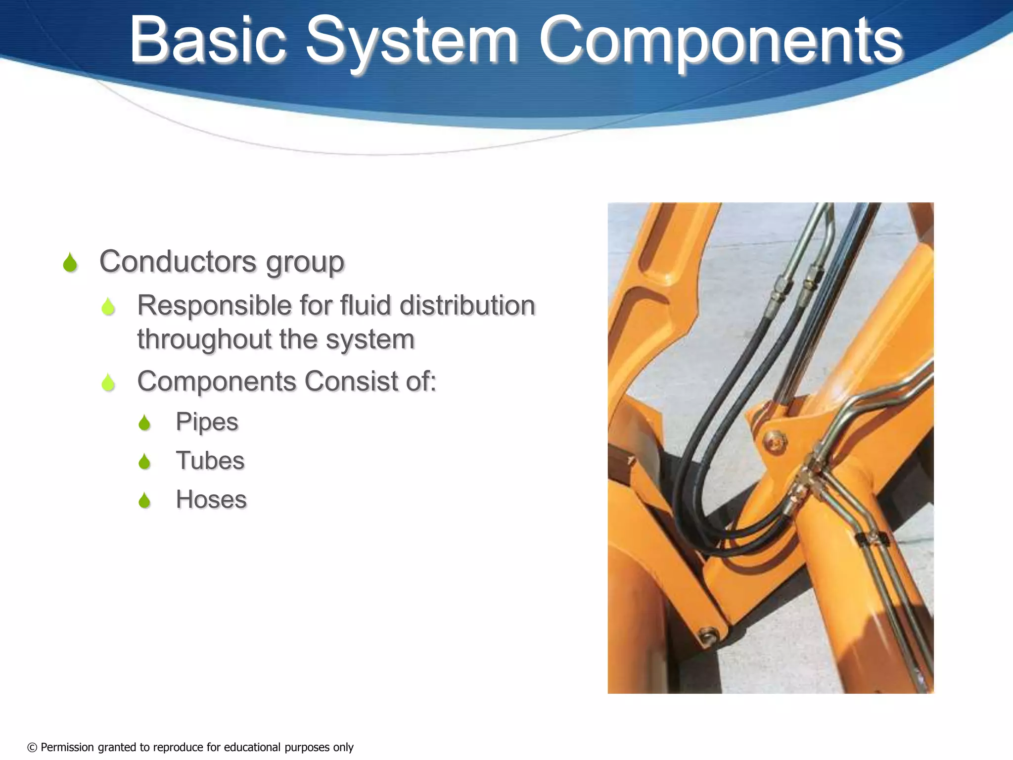
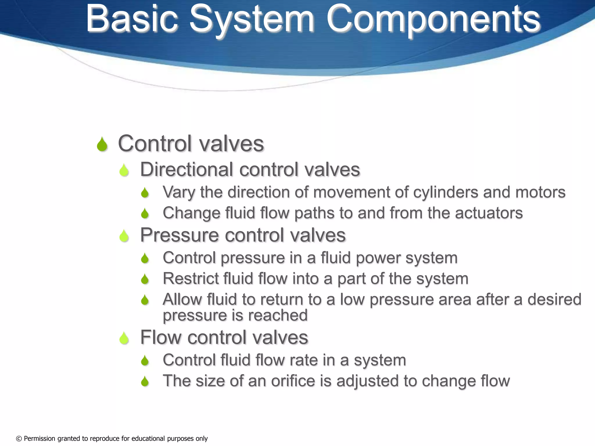
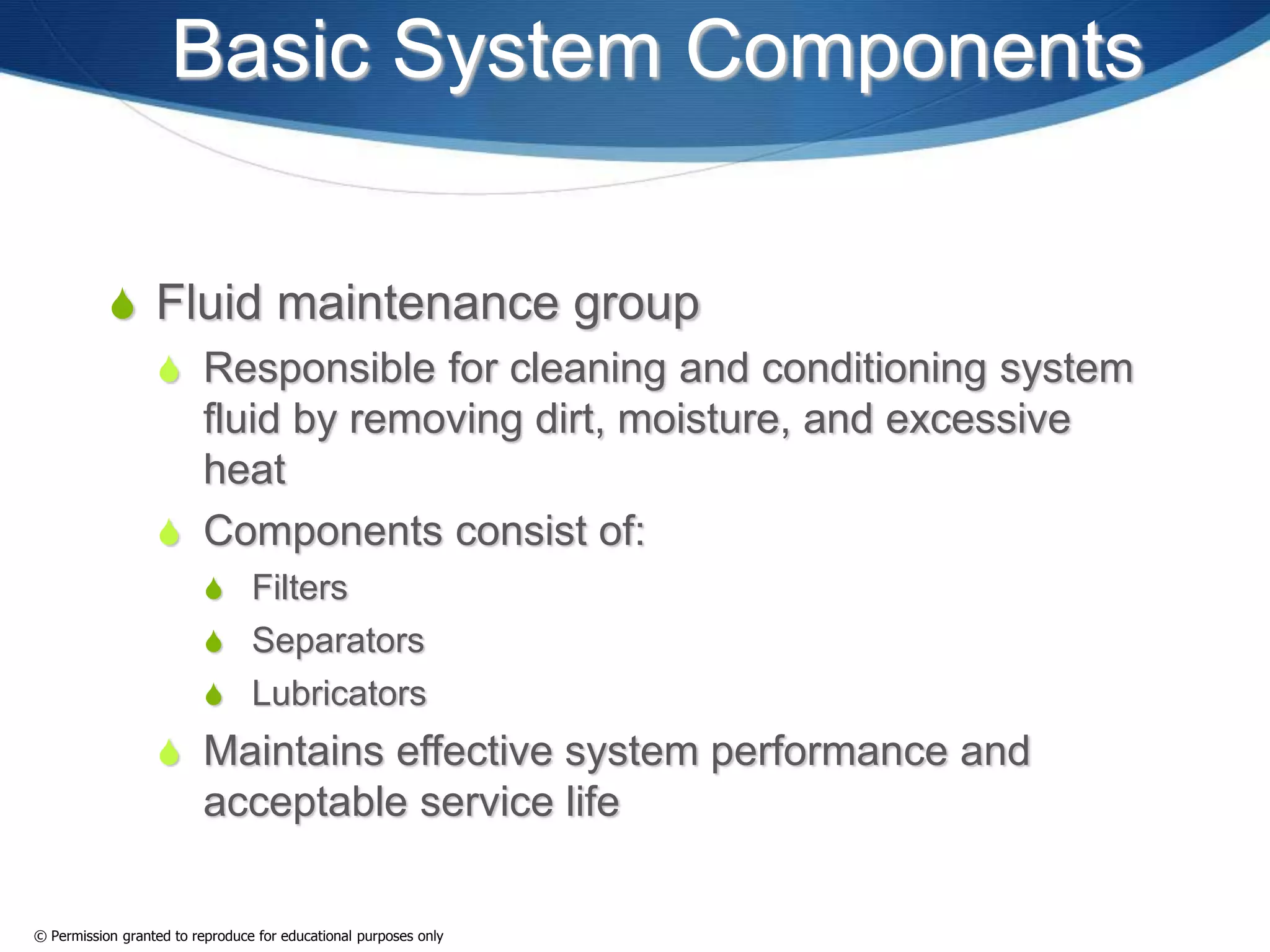
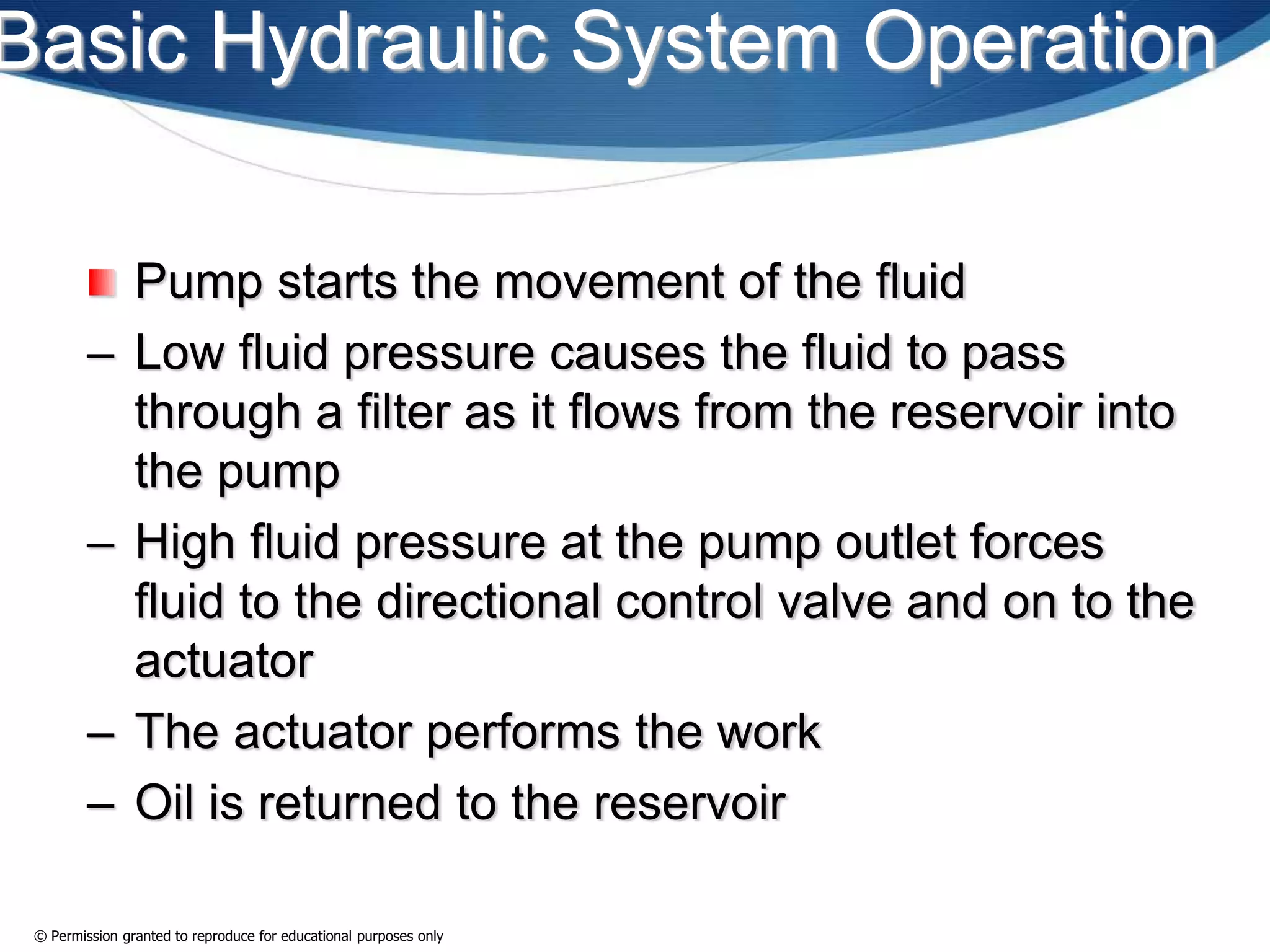
Fluid Power System Basics
This lesson follows Chapter 1 and 2 in the Fluid
Power book by James R. Daines
© Permission granted to reproduce for educational purposes only
FLUID POWER
 Any process, device, or system that converts, transmits,
distributes, or contols power through the use of a pressurized
liquid or gas.
© Permission granted to reproduce for educational purposes only
Layout of a Fluid Power System
 An example of a fluid power system layout is found in the
picture below. It consists of a prime mover (ex. a motor)
attached to a pump or compressor, pressurizing a fluid or a
gas, and transmitting through lines to an actuator that
performs work.
© Permission granted to reproduce for educational purposes only
Fluid Power Classifications
 Fluid power systems are generally grouped under two broad
classifications:
 Hydraulics
 Pneumatics
 Hydraulic systems use liquid (oil) as the system fluid
 Pneumatic systems use gas (air) as the system fluid.
© Permission granted to reproduce for educational purposes only
Chapter 1
Introduction to Fluid Power
© Permission granted to reproduce for educational purposes only
Objectives
 Definition fluid power, including hydraulic and pneumatic
systems.
 How fluid power affects our society, including several
examples.
 Advantages and disadvantages of fluid power systems.
 Historical development of the fluid power industry.
© Permission granted to reproduce for educational purposes only
FLUID POWER SYSTEM
EXAMPLES
 Do you know any fluid power systems in your daily life?
© Permission granted to reproduce for educational purposes only
EVERYDAY FLUID POWER
SYSTEM EXAMPLES
 drinking water supply system
 Showering water system
 HVAC Units
 Transmission, brakes, air conditioning, ventilation, engine
lubrication, and cooling systems on vehicles
 Lawn mower
 Your local garbage truck
© Permission granted to reproduce for educational purposes only
EVERYDAY FLUID POWER
SYSTEM EXAMPLES
 Snow plows
 Construction and mining equipment
 Jaws of life
 Robots
 Water laser machines
 And many more examples…
© Permission granted to reproduce for educational purposes only
Example of hydraulics under the
hood of your car/truck.
© Permission granted to reproduce for educational purposes only
Example of pneumatics on the street.
PhotoDisc
© Permission granted to reproduce for educational purposes only
Example of hydraulics in your lawn
Glowimages
© Permission granted to reproduce for educational purposes only
Example of hydraulics in the garage
CONCLUSION – FLUID POWER SYSTEM
EXAMPLES
 Business and industry use fluid power systems to operate.
 Fluid power systems influence almost every product in some
way.
© Permission granted to reproduce for educational purposes only
HYDRAULIC VS.
PNEUMATIC
© Permission granted to reproduce for educational purposes only
Hydraulic Fluid Power Systems
 Hydraulic systems are:
 accurate
 best at higher pressures
 slow
 made up of heavier components that can resist abuse.
© Permission granted to reproduce for educational purposes only
Pneumatic Fluid Power
Systems
 Pneumatic systems are:
 less accurate than hydraulic systems
 best at lower pressures
 fast
 Made up of light weight components
© Permission granted to reproduce for educational purposes only
Fluid Power Systems
 Advantages of both include easy control of:
 Force
 Torque
 Speed
 Direction of actuators
© Permission granted to reproduce for educational purposes only
FLUID POWER HISTORY
© Permission granted to reproduce for educational purposes only
What does a sail boat have to
do with Fluid Power?
© Permission granted to reproduce for educational purposes only
Fluid Power History
 The natural movement of air and water was used in the
earliest applications of fluid power.
 Up into the Industrial Revolution, wind and watermills were
used as prime movers to provide power.
 These wind and watermills had very small power outputs.
Glowimages
© Permission granted to reproduce for educational purposes only
Fluid Power History
 Archimedes discovered the principle of buoyancy. This is
one of the earliest recorded scientific theories.
 Scientists such as Pascal, Boyle, Charles, Reynolds, as
well as other scientists provided theoretical base
information of fluids in scientific and industrial applications.
© Permission granted to reproduce for educational purposes only
Fluid Power History
 James Watt
 Instrumental in the operation of the
steam engine, which influenced many
aspects of the Industrial Revolution
Comstock
© Permission granted to reproduce for educational purposes only
Fluid Power History
 In the early 1900s, compact, self-contained power
units, which contained the prime mover, pump, and
reservoir, were developed, which had considerable
influence on the development of fluid power as we
know it today.
© Permission granted to reproduce for educational purposes only
Self-contained Power Unit
Example
Continental Hydraulics
© Permission granted to reproduce for educational purposes only
Chapter 2
Fluid Power Systems
The Basic System
© Permission granted to reproduce for educational purposes only
Objectives
 Fluid Power System Functions.
 Basic structure of fluid power systems.
 Basic component groups involved in fluid power
systems.
© Permission granted to reproduce for educational purposes only
Objectives
 Component functions involved in basic fluid power systems
 Similarities and differences of hydraulic and pneumatic
systems
 Basic hydraulic and pneumatic systems operations
© Permission granted to reproduce for educational purposes only
Fluid Power System
Functions
© Permission granted to reproduce for educational purposes only
Fluid Power System
Functions
 Made up of components designed to perform specific tasks
 The components act together to perform desired work
© Permission granted to reproduce for educational purposes only
Fluid Power System
Functions
 Fluid power systems perform five functions during
operation:
 Energy conversion
 Fluid distribution
 Fluid control
 Work performance
 Fluid maintenance
© Permission granted to reproduce for educational purposes only
BASIC COMPONENTS OF
BOTH HYDRAULIC AND
PNEUMATIC SYSTEMS
© Permission granted to reproduce for educational purposes only
Structure of Fluid Power
Systems
 There are groupings of components that
make up the structure of a Fluid Power
System
 Power unit group
 Actuators group
 Conductors group
 Control valves group
 Fluid maintenance group
 The component groups above perform
specific system functions.
© Permission granted to reproduce for educational purposes only
Basic System Components
 Power unit group
 Responsible primarily for energy conversion
 Components consist of:
 Prime mover
 Pump or compressor
 Reservoir or receiver
© Permission granted to reproduce for educational purposes only
Basic System Components
 Power unit group
 The prime movers are most often electric motors
and internal combustion engines
 The prime mover rotates the pump or compressor
to produce the fluid flow
 Internal pressure differences create fluid flow
 Energy is transmitted throughout the system by the
fluid flow, reservoir (liquid) or receiver (gas) stores
system fluid, aids in temperature control, aids in
fluid cleaning
© Permission granted to reproduce for educational purposes only
Basic System Components
 Actuators group
 Responsible to Perform the work of the system
 Components Consist of both cylinders and motors
© Permission granted to reproduce for educational purposes only
Basic System Components
 Actuators
 Also known as cylinders (linear motion) and rotary
motors (rotary motion)
 are used in both hydraulic and pneumatic systems
© Permission granted to reproduce for educational purposes only
How An Actuator Moves
 Motion is created when pressurized fluid moves an
internal part of the actuators from a high pressure
area toward a low pressure area
(Used with permission of CNH America LLC)
© Permission granted to reproduce for educational purposes only
Basic System Components
 Conductors group
 Responsible for fluid distribution
throughout the system
 Components Consist of:
 Pipes
 Tubes
 Hoses
© Permission granted to reproduce for educational purposes only
Basic System Components
 Control valves group
 Responsible for controlling fluid pressure, flow direction, and
flow rate
 Components consist of:
 Directional control valves
 Pressure control valves
 Flow control valves
© Permission granted to reproduce for educational purposes only
Basic System Components
 Control valves
 Directional control valves
 Vary the direction of movement of cylinders and motors
 Change fluid flow paths to and from the actuators
 Pressure control valves
 Control pressure in a fluid power system
 Restrict fluid flow into a part of the system
 Allow fluid to return to a low pressure area after a desired
pressure is reached
 Flow control valves
 Control fluid flow rate in a system
 The size of an orifice is adjusted to change flow
© Permission granted to reproduce for educational purposes only
Basic System Components
 Fluid maintenance group
 Responsible for cleaning and conditioning system
fluid by removing dirt, moisture, and excessive
heat
 Components consist of:
 Filters
 Separators
 Lubricators
 Maintains effective system performance and
acceptable service life
© Permission granted to reproduce for educational purposes only
BASIC SYSTEM
OPERATION
© Permission granted to reproduce for educational purposes only
Basic Hydraulic System Operation
Pump starts the movement of the fluid
– Low fluid pressure causes the fluid to pass
through a filter as it flows from the reservoir into
the pump
– High fluid pressure at the pump outlet forces
fluid to the directional control valve and on to the
actuator
– The actuator performs the work
– Oil is returned to the reservoir
© Permission granted to reproduce for educational purposes only
Basic Pneumatic System
Operation
 Compressor starts the movement of the gas
– Low gas pressure causes the gas to pass through a filter as it
flows from the atmosphere into the compressor
– High gas pressure at the compressor outlet forces the gas to the
receiver for storage under pressure until needed by the
workstations.
– Pressurized gas is distributed to system workstations where it is
regulated, filtered, and lubricated before moving on to the
actuator.
– Actuator performs work.
– Gas is discharged into atmosphere after work is performed.
© Permission granted to reproduce for educational purposes only
Week 1 Homework
Assignment
In Lab Manual, contributes to homework grade:
1. Chapter 1 and 2 Key Terms Sheets
2. Chapter 1 and 2 Quizzes
3. Activity 1-1 in Lab Manual
Homework Assignment

2015 02-05 emet 135 week 1 presentation

  • 1.
    Fluid Power SystemBasics This lesson follows Chapter 1 and 2 in the Fluid Power book by James R. Daines © Permission granted to reproduce for educational purposes only
  • 2.
    FLUID POWER  Anyprocess, device, or system that converts, transmits, distributes, or contols power through the use of a pressurized liquid or gas. © Permission granted to reproduce for educational purposes only
  • 3.
    Layout of aFluid Power System  An example of a fluid power system layout is found in the picture below. It consists of a prime mover (ex. a motor) attached to a pump or compressor, pressurizing a fluid or a gas, and transmitting through lines to an actuator that performs work. © Permission granted to reproduce for educational purposes only
  • 4.
    Fluid Power Classifications Fluid power systems are generally grouped under two broad classifications:  Hydraulics  Pneumatics  Hydraulic systems use liquid (oil) as the system fluid  Pneumatic systems use gas (air) as the system fluid. © Permission granted to reproduce for educational purposes only
  • 5.
    Chapter 1 Introduction toFluid Power © Permission granted to reproduce for educational purposes only
  • 6.
    Objectives  Definition fluidpower, including hydraulic and pneumatic systems.  How fluid power affects our society, including several examples.  Advantages and disadvantages of fluid power systems.  Historical development of the fluid power industry. © Permission granted to reproduce for educational purposes only
  • 7.
    FLUID POWER SYSTEM EXAMPLES Do you know any fluid power systems in your daily life? © Permission granted to reproduce for educational purposes only
  • 8.
    EVERYDAY FLUID POWER SYSTEMEXAMPLES  drinking water supply system  Showering water system  HVAC Units  Transmission, brakes, air conditioning, ventilation, engine lubrication, and cooling systems on vehicles  Lawn mower  Your local garbage truck © Permission granted to reproduce for educational purposes only
  • 9.
    EVERYDAY FLUID POWER SYSTEMEXAMPLES  Snow plows  Construction and mining equipment  Jaws of life  Robots  Water laser machines  And many more examples… © Permission granted to reproduce for educational purposes only
  • 10.
    © Permission grantedto reproduce for educational purposes only Example of hydraulics under the hood of your car/truck.
  • 11.
    © Permission grantedto reproduce for educational purposes only Example of pneumatics on the street.
  • 12.
    PhotoDisc © Permission grantedto reproduce for educational purposes only Example of hydraulics in your lawn
  • 13.
    Glowimages © Permission grantedto reproduce for educational purposes only Example of hydraulics in the garage
  • 14.
    CONCLUSION – FLUIDPOWER SYSTEM EXAMPLES  Business and industry use fluid power systems to operate.  Fluid power systems influence almost every product in some way. © Permission granted to reproduce for educational purposes only
  • 15.
    HYDRAULIC VS. PNEUMATIC © Permissiongranted to reproduce for educational purposes only
  • 16.
    Hydraulic Fluid PowerSystems  Hydraulic systems are:  accurate  best at higher pressures  slow  made up of heavier components that can resist abuse. © Permission granted to reproduce for educational purposes only
  • 18.
    Pneumatic Fluid Power Systems Pneumatic systems are:  less accurate than hydraulic systems  best at lower pressures  fast  Made up of light weight components © Permission granted to reproduce for educational purposes only
  • 20.
    Fluid Power Systems Advantages of both include easy control of:  Force  Torque  Speed  Direction of actuators © Permission granted to reproduce for educational purposes only
  • 21.
    FLUID POWER HISTORY ©Permission granted to reproduce for educational purposes only
  • 22.
    What does asail boat have to do with Fluid Power? © Permission granted to reproduce for educational purposes only
  • 23.
    Fluid Power History The natural movement of air and water was used in the earliest applications of fluid power.  Up into the Industrial Revolution, wind and watermills were used as prime movers to provide power.  These wind and watermills had very small power outputs. Glowimages © Permission granted to reproduce for educational purposes only
  • 24.
    © Permission grantedto reproduce for educational purposes only
  • 25.
    Fluid Power History Archimedes discovered the principle of buoyancy. This is one of the earliest recorded scientific theories.  Scientists such as Pascal, Boyle, Charles, Reynolds, as well as other scientists provided theoretical base information of fluids in scientific and industrial applications. © Permission granted to reproduce for educational purposes only
  • 26.
    Fluid Power History James Watt  Instrumental in the operation of the steam engine, which influenced many aspects of the Industrial Revolution Comstock © Permission granted to reproduce for educational purposes only
  • 27.
    Fluid Power History In the early 1900s, compact, self-contained power units, which contained the prime mover, pump, and reservoir, were developed, which had considerable influence on the development of fluid power as we know it today. © Permission granted to reproduce for educational purposes only
  • 28.
    Self-contained Power Unit Example ContinentalHydraulics © Permission granted to reproduce for educational purposes only
  • 29.
    Chapter 2 Fluid PowerSystems The Basic System © Permission granted to reproduce for educational purposes only
  • 30.
    Objectives  Fluid PowerSystem Functions.  Basic structure of fluid power systems.  Basic component groups involved in fluid power systems. © Permission granted to reproduce for educational purposes only
  • 31.
    Objectives  Component functionsinvolved in basic fluid power systems  Similarities and differences of hydraulic and pneumatic systems  Basic hydraulic and pneumatic systems operations © Permission granted to reproduce for educational purposes only
  • 32.
    Fluid Power System Functions ©Permission granted to reproduce for educational purposes only
  • 33.
    Fluid Power System Functions Made up of components designed to perform specific tasks  The components act together to perform desired work © Permission granted to reproduce for educational purposes only
  • 34.
    Fluid Power System Functions Fluid power systems perform five functions during operation:  Energy conversion  Fluid distribution  Fluid control  Work performance  Fluid maintenance © Permission granted to reproduce for educational purposes only
  • 35.
    BASIC COMPONENTS OF BOTHHYDRAULIC AND PNEUMATIC SYSTEMS © Permission granted to reproduce for educational purposes only
  • 36.
    Structure of FluidPower Systems  There are groupings of components that make up the structure of a Fluid Power System  Power unit group  Actuators group  Conductors group  Control valves group  Fluid maintenance group  The component groups above perform specific system functions. © Permission granted to reproduce for educational purposes only
  • 37.
    Basic System Components Power unit group  Responsible primarily for energy conversion  Components consist of:  Prime mover  Pump or compressor  Reservoir or receiver © Permission granted to reproduce for educational purposes only
  • 38.
    Basic System Components Power unit group  The prime movers are most often electric motors and internal combustion engines  The prime mover rotates the pump or compressor to produce the fluid flow  Internal pressure differences create fluid flow  Energy is transmitted throughout the system by the fluid flow, reservoir (liquid) or receiver (gas) stores system fluid, aids in temperature control, aids in fluid cleaning © Permission granted to reproduce for educational purposes only
  • 39.
    Basic System Components Actuators group  Responsible to Perform the work of the system  Components Consist of both cylinders and motors © Permission granted to reproduce for educational purposes only
  • 40.
    Basic System Components Actuators  Also known as cylinders (linear motion) and rotary motors (rotary motion)  are used in both hydraulic and pneumatic systems © Permission granted to reproduce for educational purposes only
  • 41.
    How An ActuatorMoves  Motion is created when pressurized fluid moves an internal part of the actuators from a high pressure area toward a low pressure area (Used with permission of CNH America LLC) © Permission granted to reproduce for educational purposes only
  • 42.
    Basic System Components Conductors group  Responsible for fluid distribution throughout the system  Components Consist of:  Pipes  Tubes  Hoses © Permission granted to reproduce for educational purposes only
  • 43.
    Basic System Components Control valves group  Responsible for controlling fluid pressure, flow direction, and flow rate  Components consist of:  Directional control valves  Pressure control valves  Flow control valves © Permission granted to reproduce for educational purposes only
  • 44.
    Basic System Components Control valves  Directional control valves  Vary the direction of movement of cylinders and motors  Change fluid flow paths to and from the actuators  Pressure control valves  Control pressure in a fluid power system  Restrict fluid flow into a part of the system  Allow fluid to return to a low pressure area after a desired pressure is reached  Flow control valves  Control fluid flow rate in a system  The size of an orifice is adjusted to change flow © Permission granted to reproduce for educational purposes only
  • 45.
    Basic System Components Fluid maintenance group  Responsible for cleaning and conditioning system fluid by removing dirt, moisture, and excessive heat  Components consist of:  Filters  Separators  Lubricators  Maintains effective system performance and acceptable service life © Permission granted to reproduce for educational purposes only
  • 46.
    BASIC SYSTEM OPERATION © Permissiongranted to reproduce for educational purposes only
  • 47.
    Basic Hydraulic SystemOperation Pump starts the movement of the fluid – Low fluid pressure causes the fluid to pass through a filter as it flows from the reservoir into the pump – High fluid pressure at the pump outlet forces fluid to the directional control valve and on to the actuator – The actuator performs the work – Oil is returned to the reservoir © Permission granted to reproduce for educational purposes only
  • 48.
    Basic Pneumatic System Operation Compressor starts the movement of the gas – Low gas pressure causes the gas to pass through a filter as it flows from the atmosphere into the compressor – High gas pressure at the compressor outlet forces the gas to the receiver for storage under pressure until needed by the workstations. – Pressurized gas is distributed to system workstations where it is regulated, filtered, and lubricated before moving on to the actuator. – Actuator performs work. – Gas is discharged into atmosphere after work is performed. © Permission granted to reproduce for educational purposes only
  • 49.
    Week 1 Homework Assignment InLab Manual, contributes to homework grade: 1. Chapter 1 and 2 Key Terms Sheets 2. Chapter 1 and 2 Quizzes 3. Activity 1-1 in Lab Manual Homework Assignment