Downloaded 270 times
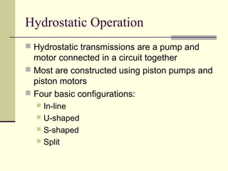

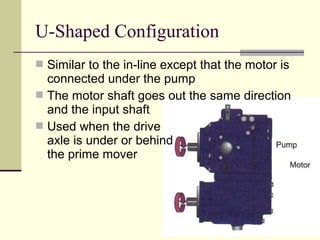
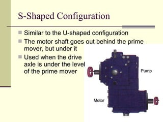


Hydrostatic transmissions use a pump and motor connected in a hydraulic circuit to transmit power. They have four basic configurations: in-line, U-shaped, S-shaped, and split. Hydrostatic transmissions offer advantages like operating over a wide speed range without changing the prime mover speed and providing dynamic braking. They use either an open or closed hydraulic circuit and precisely control fluid flow and motor speed through variable displacement pumps and swash plates.


![General motors hydra-matic 4 l60e [2003 ð¦.rus]](https://cdn.slidesharecdn.com/ss_thumbnails/generalmotors-hydra-matic4l60e2003-rus-121022002527-phpapp02-thumbnail.jpg?width=640&height=640&fit=bounds)


