Downloaded 588 times

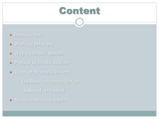
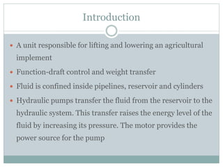
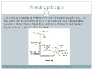


The document provides an overview of tractor hydraulics, detailing the working principles, components, types of hydraulic systems, and the importance of maintenance. It explains how hydraulic systems operate based on Pascal's law and includes descriptions of key components such as pumps, valves, and motors. Additionally, it covers control methods for implements and emphasizes the need for regular maintenance to ensure system efficiency.


