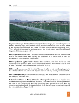
1 | P a g e
SAQIB IMRAN 0341-7549889 1
Assala mu alykum My Name is saqib imran and I am the
student of b.tech (civil) in sarhad univeristy of
science and technology peshawer.
I have written this notes by different websites and
some by self and prepare it for the student and also
for engineer who work on field to get some knowledge
from it.
I hope you all students may like it.
Remember me in your pray, allah bless me and all of
you friends.
If u have any confusion in this notes contact me on my
gmail id: Saqibimran43@gmail.com
or text me on 0341-7549889.
Saqib imran.
2 | P a g e
SAQIB IMRAN 0341-7549889 2
Design, Maintenance, Types & Components
of Hydraulic Structures
Definition of Hydraulic Structures:
Hydraulic structures are anything that can be used to divert, restrict, stop, or otherwise
manage the natural flow of water. They can be made from materials ranging from large
rock and concrete to obscure items such as wooden timbers or tree trunks. A dam, for
instance, is a type of hydraulic structure used to hold water in a reservoir as potential
energy, just as a weir is a type of hydraulic structure which can be used to pool water
for irrigation, establish control of the bed (grade control) or, as a new innovative
technique, to divert flow away from eroding banks or into diversion channels for flood
control.
A hydraulic structure is a structure submerged or partially submerged in any body of
water, which disrupts the natural flow of water. They can be used to divert, disrupt or
completely stop the flow. An example of a hydraulic structure would be a dam, which
slows the normal flow rate of river in order to power turbines. A hydraulic structure can
be built in rivers, a sea, or any body of water where there is a need for a change in the
natural flow of water.
Factors Affecting Type of Canal Lining
3 | P a g e
SAQIB IMRAN 0341-7549889 3
Following are the Factors Affecting Type of Canal Lining:
Imperviousness of Canal Lining
When the canal passes through the sandy soil the seepage loss is at maximum and the canal
is unstable. So, to make the canal perfectly impervious and reasonably stable, the most
impervious types of linings should be recommended such as cement concrete etc.
Smoothness of Canal Lining
The smoothness of the canal bed and sides increases the velocity of flow which further
increases the discharge of the canal. Due to the increased discharge, the duty of water will
be more. So, to increase the duty, the canal surface should be made smooth. The lining like
cement concrete, pre-cast cement concrete etc gives smooth surface to the canal.
Durability of Canal Lining
4 | P a g e
SAQIB IMRAN 0341-7549889 4
The ultimate benefit of any project depends on the durability of the hydraulic structures,
canals, etc. So, to make the canal section more durable against all adverse effects like
scouring, erosion, weather action, etc. the most strong and impervious types of lining
should be recommended.
Economy of Canal Lining
The lining should be economically viable with the benefits that may be accrued from the
expected revenue, yield of crop, etc. So, by studying the overall benefits the type of lining
should be recommended.
Site Condition
Another Factor Affecting Type of Canal Lining is the site condition. The canal may pass
through the marshy land, loose sandy soil, alluvial soil, black clayey soil, hard soil, etc. So,
according to the soil and site condition the type of lining should be recommended.
Life of Project
Every project should be designed to serve the future three or four decades successfully.
The type of lining should be recommended keeping in mind the life of the project.
Availability of Construction Materials
The expenditure of lining depends on the availability of construction materials, carriage
charges, etc. To reduce the expenditure of lining, the materials which are available in the
vicinity of the project should be utilized.
Factors Affecting Design of a Barrage
5 | P a g e
SAQIB IMRAN 0341-7549889 5
Factors affecting the Design of a Barrage are as follows:
1. Estimation of Design Flood
2. Hydraulic Units
3. Width of Barrage
4. Afflux
5. Tail Water Rating Curve
6. Crest Levels
7. Discharges through a Barrage (Free Flow Conditions)
8. Discharge through a Barrage (Submerged Flow Conditions)
1. Fane's Curve
2. Gibson's Curve
Definitions of Technical Terms in Hydraulic
Structures
Khadir:
Flood plain of river. Khadir axis is a line passing through the center of the river course
between the two high banks up to back water effect.
Weir axis:
Line along which the crest of the weir is laid.
6 | P a g e
SAQIB IMRAN 0341-7549889 6
River axis:
Line parallel to Khadir axis at the center of weir or barrage axis between the abutments.
Headwork axis:
Line perpendicular to weir axis at the center of weir abutments.
When the angle between the headwork axis and the river axis exceeds 10°, the problem
arises of concentration of flow on one side and island formation due to heavy silting within
the guide bank on the other side. If the river axis is to the right of headwork axis, the
concentration of flow is generally generally on the left side with consequent tendency to
form an island on the right side and vice versa.
1. Should be located far below the influence of two river
2. Preferably located in the center of plain asymmetry result in shoals formation
Retrogression:
It is a temporary phenomenon which occurs after the construction of barrage in the river
flowing through alluvial soil. As a result of back water effect and increase in the depth, the
velocity of water decreases resulting in deposition of sedimentation load. The water
flowing through the barrage have less silt, so water picks up silt from downstream bed.
This results in lowering d/s river bed to a few miles. This is known as retrogression. It may
occur for the first few years and bed levels often recover their previous level. Within a few
years, water flowing over the weir has a normal silt load and this cycle reverses. Then due
to greater depth, silt is deposited and d/s bed recovers to equilibrium. Retrogression value
is minimum for flood discharge and maximum for low discharge. The values vary (2-8.5)
ft.
Accretion:
It is the reverse of retrogression and normally occurs u/s, although it may occur d/s after
the retrogression cycle is complete. There is no accurate method for calculating the values
of retrogression and accretion but the values which have been calculated from different
barrages can be used as a guideline.
River Training Works and other Definitions
7 | P a g e
SAQIB IMRAN 0341-7549889 7
River training works
It includes guide banks, marginal bunds, spurs etc. Functions are:
 To provide and non-tortuous approach to weir.
 To prevent the river from out-flanking the weir.
 To prevent additional area to be submerged due to afflux.
 To prevent erosion of the river banks (protective works).
 To ensure smooth and axial flow of water, to prevent the river from out ------ the works
due to change in its course.
River Training Works
Guide banks:
Guide Bank are earthen embankments with stone pitching in the slopes facing water, to
guide the river through the barrage, These river training works are provided for rivers
flowing in planes, upstream and downstream of the hydraulic structures or bridges built on
the river. Guide banks guide the river water flow through the barrage.
Guide banks force the river into restricted channel, to ensure almost axial flow near the
weir site. (embankments in continuation of G-Banks. To contain flood within flood plains)
8 | P a g e
SAQIB IMRAN 0341-7549889 8
Marginal Bunds:
Marginal bunds are flood embankments in continuation of guide banks designed to contain
the floods within the flood plain of the river. Both height and length vary according to back
water effect caused by the barrage. They are not provided with stone pitching and fully
cover the back- water length. Provided on the upstream in order to protect the area from
submergence due to rise in HFL, caused by afflux.
Groynes or spurs:
Marginal bunds are also called as ‘Spurs’.
 Embankment type structures constructed transverse to river flood, extending from the
banks into the river (also transverse dykes)
 Protect the bank from which they are extended by deflecting the current away from the
bank.
Factors Affecting Structure Shape and
Capacity of Culverts
9 | P a g e
SAQIB IMRAN 0341-7549889 9
10 | P a g e
SAQIB IMRAN 0341-7549889 10
The following information applies to the design of reinforced concrete culverts:
a. Location.
Ideally, the axis of a culvert should coincide with that of the natural stream bed and the
structure should be straight and short. This may require modification of the culvert
alignment and grade. Often it is more practical to construct the culvert at right angles to
the roadway. However, the cost of any change in stream channel location required to
accomplish this should be balanced against the cost of a skewed alignment of the culvert,
and changes in channel hydraulics should be considered.
b. Grade and camber.
The culvert invert gradient should be the same as the natural stream bed to minimize
erosion and silting problems. Foundation settlement should be countered by cambering
the culvert to ensure positive drainage.
c. Entrance and outlet conditions.
It is often necessary to enlarge the natural channel a considerable distance downstream
of the culvert to prevent back water from entering the culvert. Also, enlargement of the
culvert entrance may be required to prevent ponding above the culvert entrance.The
entrance and outlet conditions of the culvert structure directly impact its hydraulic
capacity. Rounding or beveling the entrance corners increases the hydraulic capacity,
especially for short culverts of small cross section. Scour problems can occur when abrupt
changes are made to the stream-bed flowline at the entrance or outlet of the culvert.
Determination of Discharge Capacity and
Number of Spillways
11 | P a g e
SAQIB IMRAN 0341-7549889 11
The maximum discharge capacity and the number of spillways are determined by studying
the following factors:
1. By studying the flood hydrograph of past ten years, the maximum flood discharge
may be computed which is to be disposed off completely through the spillways.
2. The water level in the reservoir should never be allowed to rise above the maximum
pool level and should remain in normal pool level. So, the volume of water collected
between maximum pool level and minimum pool level computed, which indicates
the discharge capacity of spillways.
12 | P a g e
SAQIB IMRAN 0341-7549889 12
3. The maximum flood discharge may also be computed from other investigation like,
rainfall records, flood routing, empirical flood discharge formulae, etc.
4. From the above factors the highest flood discharge is ascertained to fix the discharge
capacity of spillways.
5. The natural calamities are beyond the grip of human being. So, an allowance of
about 25 % should be given to the computed highest flood discharge which is to be
disposed off.
6. The size and number of spillways are designed according to the design discharge.
Factors Affecting Location and Necessity of
Spillways
Necessity of Spillways
1. The height of the dam is always fixed according to the maximum reservoir capacity.
The normal pool level indicates the maximum capacity of the reservoir. The water
is never stored in the reservoir above this level. The dam may fail by over turning
so, for the safety of the dam the spillways are essential.
2. The top of the dam is generally utilized by making road. The surplus water is not
be allowed to over top the dam, so to stop the over topping by the surplus water,
the spillways become extremely essential.
3. To protect the downstream base and floor of the dam from the effect of scouring
and erosion, the spillways are provided so that the excess water flows smoothly.
13 | P a g e
SAQIB IMRAN 0341-7549889 13
Location of Spillway
Generally, the spillways are provided at the following places:
 Spillways may be provided within the body of the dam.
 Spillways may sometimes be provided at one side or both sides of the dam.
 Sometimes by-pass spillway is provided which is completely separate from the
dam.
Design of Weir and Conditions for Stability
& Maximum stress
In any hydropower projects the diversion structures occupies the key position. Among
these diverging structures weir is the most commonly used structure, because of its simple
design and operation. Different types of weir can be used as diverging structures some of
them are given below:
1. Sharp crested weir
2. Broad crested weir
3. Ogee weir
4. Tyrolean weir
5. weir with lateral intake etc
Lets consider a general case of weir design.
14 | P a g e
SAQIB IMRAN 0341-7549889 14
Forces on Weir
The forces acting on a weir built on a impervious foundation may be static or dynamic.
The static forces include:
1. Normal water pressure on the upstream face of the weir.
2. Normal water pressure on the downstream face of the weir.
3. The weight of the water supported by the crest and the weight of the weir.
Dynamic forces
The dynamic forces acting on weir includes:
1. Erosive or the scouring forces on the downstream side of the weir produced either by high
velocity or by the impact of water pouring over the weir.
2. The force of impact of floating matter against the crest on the upstream side of the weir.
Conditions for Stability of Weirs
There are some conditions that are required to be satisfied for the stability of the weir.
These includes:
1. There must be no tension in the masonry or in the contact plane between weir and the
foundation.
2. There must be no overturning.
3. There must be no tendency to slide on the joint with the foundation or any horizontal plane
above the base.
4. The maximum toe and heel pressures in foundations should not exceed the prescribed safe
limits. Failure by crushing is not considered here, as it generally does not occur, being a
low structure.
15 | P a g e
SAQIB IMRAN 0341-7549889 15
Condition of Maximum Stress on Weir
In the case of a dam the condition for maximum stress is when the water level above the
base is maximum. i. e. when the head is maximum. But in case of a weir design, when the
discharge increases the near water level also builds up and the difference between them
will become less and less. So, the weir is subjected to maximum head when the water
level on the upstream side is maximum and no water passes over the crest.
Design of Water Channel (Canals)
The channel is the same thing that is used for the water carriage purpose, however in
case of hydropower projects the channel that takes water from the intake (Diversion
Structure) is usually called connecting channel. It's tunnel is to be used in between the
intake and power house otherwise called headrace channel, if no tunnel is to be used
in between the intake and power house.
Lets take a general Example of design of small channel with design discharge of 390
lit/sec.
Design of Canal / Channel Design
Design discharge of the channel Q = 390 lps
Length of the channel L = 65 m
Cross sectional area of the channel A = Q / V = 0.39 / 1.0
= 0.39 m2
V = max. velocity permissible through the channel = 1.0 m/s
Cross sectional dimensions of the Water channel
From economic consideration
Top width = T = 2d
Area A = T x d = 2d2
Depth d =0.39/2 = 0.44 m
Provide a free board of 15cm
Total depth D = 0.60 m
16 | P a g e
SAQIB IMRAN 0341-7549889 16
Base width B = 0.44 x 2 = 0.88 m ~ 0.9 m
Hydraulic radius R = wetted area = A/P = 0.90 x 0.45
wetted perimeter 0.90 + 0.45 x 2 = 0.225
Channel bed slope S = nv 2 R 2/3 = 0.015 x 1.0 2 = 0.00164(0.225) 2/3
Head loss = Channel bed slope x Length of the channel = 0.00164x 65 = 0.11m
Surge Tanks, Function and Types of Surge
Tanks
Definition
Surge tank (or surge chamber) is a device introduced within a hydropower water
conveyance system having a rather long pressure conduit to absorb the excess pressure
rise in case of a sudden valve closure. The surge tank is located between the almost
horizontal or slightly inclined conduit and steeply sloping penstock and is designed as a
chamber excavated in the mountain.
It also acts as a small storage from which water may be supplied in case of a sudden valve
opening of the turbine. In case of a sudden opening of turbine valve, there are chances
of penstock collapse due to a negative pressure generation, if there is no surge tank.
17 | P a g e
SAQIB IMRAN 0341-7549889 17
Surge Tank Function
When the valve in a hydroelectric power plant is suddenly completely closed, because of
its small inertia the water in the penstock stops almost at once. The water in the pipeline,
with large inertia retards slowly. The difference in flows between pipeline and penstock
causes a rise in the water level in the surge tank. The water level rises above the static
level of the reservoir water, producing a counter-pressure so that water in the pipeline
flows towards the reservoir and the level of water in the surge tank drops. In the absence
of damping, oscillation would continue indefinitely with the same amplitude.
The flow into the surge tank and water level in the tank at any time during the oscillation
depends on the dimension of the pipeline and tank and on the type of valve movement. The
main functions of a surge tank are:
1. It reduces the amplitude of pressure fluctuations by reflecting the incoming pressure waves
2. It improves the regulation characteristic of a hydraulic turbine.
The surge tank dimensions and location are based on the following considerations
1. The surge tank should be located as close to the power or pumping plant as possible;
2. The surge tank should be of sufficient height to prevent overflow for all conditions of
operation;
3. The bottom of surge tank should be low enough that during its operation the tank is drained
out and admit air into the turbine penstock or pumping discharge line; and
4. The surge tank must have sufficient cross sectional area to ensure stability.
Surge Tank Types
There are different types of surge tanks that are possible to be installed. Some of the most
common types of surge tanks which are as follows:
Simple Surge Tank:
A simple surge tank is a shaft connected to pressure tunnel directly or by a short connection
of cross-sectional area not less than the area of the head race tunnel.
Restricted Orifice Surge Tank:
A simple surge tank in which the inlet is throttled to improve damping of oscillations by
offering greater resistance and connected to the head race tunnel with or without a
connecting/communicating shaft
18 | P a g e
SAQIB IMRAN 0341-7549889 18
Differential Surge Tank:
Differential Surge tank is a throttled surge tank with an addition of a riser pipe may be
inside the main shaft, connected to main shaft by orifice or ports. The riser may also be
arranged on one side of throttled shaft.
In an underground development of hydropower system, tail race surge tanks are usually
provided to protect tail race tunnel from water hammer effect due to fluctuation in load.
These are located downstream of turbines which discharge into long tail race tunnels
under pressure. The necessity of tail race surge tank may be eliminated by ensuring free-
flow conditions in the tunnel but in case of long tunnels this may become uneconomical
than a surge tank.
Water Surface Oscillation
The height of the surge tank is governed by the highest possible water level that can be
expected during operation. Variations in demand initiated by a rapid opening or closure
of the valve or turbine are followed with a time lag by the water masses moving in the
tunnel. Upon the rapid and partial closure of the valve following a sudden load decrease,
water masses in the penstock are suddenly decelerated, and one part of the continuous
supply from the tunnel fills the surge tank. The water surface in the surge chamber will
be raised to above static level.
In case of rapid opening, the flow in the tunnel is smaller than the turbine demand to
supply water to the turbine. The water surface in the chamber will start to drop to below
of the steady-state level. To establish steady-flow conditions, the water surface will again
start to rise from the low point, but owing to the inertia of moving water, will again rise
over the steady-level. The cycle is repeated all over again with amplitudes reduced by
friction, i.e. the oscillation is damped. The phenomenon described is the water surface
oscillation.
Selection of a Suitable Site and Type of
Cross Drainage Work
Selection of a Suitable 'Site' for Cross Drainage Work
The following points should be considered while selecting the site of a cross-drainage
work:
 At the site, the drainage should cross the canal alignment at right angles. Such a site
provides good flow conditions and also the cost of the structure is usually a minimum.
19 | P a g e
SAQIB IMRAN 0341-7549889 19
 The stream at the site should be stable and should have stable banks.
 For economical design and construction of foundations, a firm and strong sub-stratum
should exit below the bed of the drainage at a reasonable depth.
 The site should be such that long and high approaches of the canal are not required.
 The length and height of the marginal banks and guide banks for the drainage should be
small.
 In the case of an aqueduct, sufficient headway should be available between the canal trough
and the high flood level of the drainage.
 The water table at the site should not be high, because it will create De-watering problems
for laying foundations.
 As far as possible, the site should be selected d/s of the confluence of two streams, thereby
avoiding the necessity of construction of two cross-drainage works.
 The possibility of diverting one stream into another stream upstream of the canal crossing
should also be considered and adopted, if found feasible and economical.
 A cross-drainage work should be combined with a bridge, if required. If necessary, the
bridge site can be shifted to the cross-drainage work or vice versa. The cost of the combined
structure is usually less. Moreover, the marginal banks and guide banks required for the
river training can be used as the approaches for the village roads.
Selection of a Suitable 'Type' of Cross Drainage Work
The following factors should be considered while selecting the most suitable type of the
cross-drainage work.
1. Relative levels and discharges:
The relative levels and discharges of the canal and of the drainage mainly affect type of
cross-drainage work required. The following are the broad outlines:
1. If the canal bed level is sufficiently above the H.F.L. of the drainage, an aqueduct is
selected.
2. If the F.S.L. of the canal is sufficiently below the bed level of the drainage, a super-passage
is provided.
3. If the canal bed level is only slightly below the H.F.L. of the drainage, and the drainage is
small, a siphon aqueduct is provided. If necessary, the drainage bed is depressed below the
canal.
4. If the F.S.L. of the canal is slightly above the bed level of the drainage and the canal is of
small size, a canal syphon is provided.
5. If the canal bed and the drainage bed are almost at the same level, a level crossing is
provided when the discharge in the drainage is large, and an inlet-outlet structure is
provided when the discharge in the drainage is small. However, the relative levels of the
canal and the drainage can be altered to some extent by changing the canal alignment to
have another crossing. In that case, the most suitable type of the cross-drainage work will
be selected depending upon the levels at the changed crossing.
20 | P a g e
SAQIB IMRAN 0341-7549889 20
2. Performance:
As far as possible, the structure having an open channel flow should be preferred to the
structure having a pipe flow. Therefore, an aqueduct should be preferred to a syphon
aqueduct. Likewise, a super-passage should be preferred to a canal siphon. In the case of
a syphon aqueduct and a canal syphon, silting problems usually occur at the crossing.
Moreover, in the case of a canal syphon, there is considerable loss of command due to
loss of head in the canal. The performance of inlet-outlet structures is not good and
should be avoided.
3. Provision of road:
An aqueduct is better than a super-passage because in the former, a road bridge can easily
be provided along with the canal trough at a small extra cost, whereas in the latter, a
separate road bridge is required.
4. Size of drainage:
When the drainage is of small size, a syphon aqueduct will be preferred to an aqueduct as
the latter involves high banks and long approaches. However, if the drainage is of large
size, an aqueduct is preferred.
5. Cost of earthwork:
The type of cross-drainage work which does not involve a large quantity of earthwork of
the canal should be preferred.
6. Foundation:
The type of cross-drainage work should be selected depending upon the foundation
available at the site of work.
7. Material of construction:
Suitable types of material of construction in sufficient quantity should be available near the
site for the type of cross-drainage work selected. Moreover, the soil in sufficient quantity
should be available for constructing the canal banks if the structure requires long and high
canal banks.
21 | P a g e
SAQIB IMRAN 0341-7549889 21
8. Cost of construction:
The cost of construction of cross-drainage work should not be excessive. The overall cost
of the canal banks and the cross-drainage work, including maintenance cost, should be a
minimum.
9. Permissible loss of head:
Sometimes, the type of cross-drainage is selected considering the permissible loss of head.
For example, if the head loss cannot be permitted in a canal at the site of cross-drainage, a
canal syphon is ruled out.
10. Subsoil water table:
If the subsoil water table is high, the types of cross-drainage which requires excessive
excavation should be avoided, as it would involve De-watering problems.
11. Canal alignment:
The canal alignment is sometimes changed to achieve a better type of cross-drainage work.
By changing the alignment, the type of cross-drainage can be altered. The canal alignment
is generally finalized after fixing the sites of the major cross-drainage works.
General Stability Criteria of Weirs
22 | P a g e
SAQIB IMRAN 0341-7549889 22
Stability analysis have been carried out for structures for most severe conditions of
horizontal and vertical forces. Stability criteria are aimed at ensuring the overall safety of
structure against overturning, flotation and sliding.
Overturning
The structures have been designed so that it should be safe against overturning at any
horizontal plane within the structure at the base, or at a plane below the base. The
overturning stability have been calculated by applying all the vertical forces (SV) and
lateral forces for each loading condition to the structure and, then, summing moments
(SM) caused by the consequent forces about the downstream toe. The resultant location
(RL) along the base is given as: -
Resultant Location (e)
RL = Σ M / Σ V
Allowable limits under different loading conditions are as follows:
23 | P a g e
SAQIB IMRAN 0341-7549889 23
Normal Loading
Resultant of all forces acting on structures will fall within the middle sixth of the base (i.e.
no tension allowed between concrete and foundation) and the allowable foundation
pressure will not be exceeded.
Exceptional loading
Resultant of all forces acting on the structure will remain within the middle third of the
base and allowable design foundation pressure (20% higher than for Normal loading case)
will not be exceeded.
Extreme loading
Resultant of all forces acting on the structure will remain within the middle half of the base
provided that a minimum of 75% of the base area is subject to compression and the
maximum base pressure will not exceed the allowable design foundation pressure (33%
higher than for Normal loading case).
Typical Example of Weir
Sliding
The structure have been designed so that it should be safe against sliding on any horizontal
or near-horizontal plane within the structure at the base or on any rock seam in the
foundation. Sliding stability has been checked with the following equation:
Force causing sliding = Pn
Where Pn = Σ Horizontal forces
Force resisting sliding = f (W + Pv)
Where f = Co-efficient of function between soil & concrete
W = Total weight
Pv = Σ vertical forces
The minimum factors of safety for the project are as follows: -
24 | P a g e
SAQIB IMRAN 0341-7549889 24
Loading ConditionFactor of Safety
Normal loading 1.50
Exceptional loading 1.25
Extreme loading 1.10
Where
 Normal Loading
Resultant of all forces acting on structures will fall within the middle sixth of the base (i.e.
no tension allowed between concrete and foundation) and the allowable foundation
pressure will not be exceeded.
 Exceptional loading
Resultant of all forces acting on the structure will remain within the middle third of the
base and allowable design foundation pressure (20% higher than for Normal loading case)
will not be exceeded.
 Extreme loading
Resultant of all forces acting on the structure will remain within the middle half of the
base provided that a minimum of 75% of the base area is subject to compression and the
maximum base pressure will not exceed the allowable design foundation pressure (33%
higher than for Normal loading case). For concrete structures on weak foundations, it is
usually not feasible to obtain safety factors equivalent to those prescribed for structures
on competent rock. It has been common practice to relax the factor of safety for concrete
structures on non-rock/weak rock foundations. The factor of safety is established on the
basis of results of site investigation and judgment of experienced designers.
Flotation
An empty tank constructed in water bearing soil will tend to move upwards, in the ground
or float. This affect was also considered into account in design of hydraulic structures.
Specially in the design of weir apron on d/s side. Safety against flotation of concrete
structures has been checked with the following equation:
Factor of safety = ( Σ V - U) / U
Where
25 | P a g e
SAQIB IMRAN 0341-7549889 25
Σ V = downward vertical forces
U = uplift force
The minimum factors of safety against flotation in different conditions are as follows: -
LOADING FACTOR OF SAFETY
Normal Loading 1.25
Exceptional Loading 1.15
Extreme Loading 1.05
BEARING PRESSURE
The following equation has been used to compute the bearing pressure at critical
locations on the foundation:
Where,
Fb = Bearing pressure
Σv = sum of all vertical loads
A = Area of the base
Σ M = sum of all the moments about the center of the base
Y = distance from the center of gravity of the base to the location where the bearing
pressure is to be computed
I = Moment of Inertial of the base
Cross Sectional Design of Typical Side
Channel Spillways
Definition:
A side channel spillway is one whose control weir is placed alongside and approximately
parallel to the upper portion of the spillway discharge channel. Flow over the crest falls
26 | P a g e
SAQIB IMRAN 0341-7549889 26
into a narrow trough opposite the weir, turns approximately 90 degree and then continues
into the main discharge channel.
The side channel design is concerned only with the hydraulic action in the upstream reach
of the discharge channel and is more or less independent of the details selected for the
other spillway components. Flows from the side channel can be directed into an open
discharge channel or into a closed conduit or inclined tunnel.
Flow Characteristics in Side Channel Spillways:
Flow into the side channel might enter the trough on only one side in the case of a steep
hillside location, or on both sides and over the end of the trough if it is located on a knoll
or gently sloping abutment.
Side channel spillway di Bendungan Hope, Scotland
Discharge characteristics of a side channel spillway are similar to those of an ordinary
overflow spillway and are dependent on the selected profile of the weir crest. However,
for maximum discharges the side channel flow may differ from that of the overflow
spillway in that the flow in the trough may be restricted and may partly submerge the
flow over the crest. In this case the flow characteristics are controlled by a constriction in
the channel downstream from the trough.
The constriction may be a point of critical flow in the channel, an orifice control, or a
conduit or tunnel flowing full. Although the side channel is neither hydraulically efficient
nor inexpensive, it has advantages that make it desirable for certain spillway layouts.
Where a long overflow crest is needed to limit the surcharge head and the abutments are
steep and precipitous, or where the control must be connected to a narrow discharge
channel or tunnel, the side channel spillway is often the best choice.
27 | P a g e
SAQIB IMRAN 0341-7549889 27
In side channel spillways both the incoming velocities and the channel velocities will be
relatively slow, a fairly complete intermingling of the flows will occur, thereby producing
a comparatively smooth flow in the side channel. Where the channel flow is at the super-
critical stage, the channel velocities will be high, and the intermixing of the high-energy
transverse flow with the channel stream will be rough and turbulent. The transverse flows
will tend to sweep the channel flow to the far side of the channel, producing violent wave
action with attendant vibrations. Therefore, it is evident that flows should be
performance. This can be achieved by establishing a control section downstream from the
side channel trough.
The cross-sectional shape of the side channel trough will be influenced by the overflow
crest on the one side and by the bank conditions on the opposite side. Because of
turbulence and vibrations inherent in side channel flow, a side channel design is
ordinarily not considered except where a competent foundation such as rock exists. The
channel sides will, therefore, usually be a concrete lining placed on a slope and anchored
directly to the rock.
A trapezoidal cross section is the one most often used for a side channel trough. The
width of such a channel in relation to the depth should be considered. If the width to
depth ratio is large, the depth of flow in the channel will be shallow, similar
A control section downstream from the side channel trough is achieved by constricting
(Fluming) the channel sides or elevating (Raising) the channel bottom to produce a point
of critical flow. Flows upstream from the control will be at the sub-critical stage and will
provide a maximum of depth in the side channel trough. The side channel bottom and
control dimensions are then selected so that flow in the trough opposite the crest will be
at the greatest depth possible without submerging the flow over the crest. Flow in the
discharge channel downstream from the control will be the same as that in an ordinary
channel or chute spillway.
Variations in the design can be made by assuming different bottom widths, different
channel slopes, and varying control sections. A proper and economical design can usually
be achieved after comparing several alternatives.
Sand Trap Design Criteria & Location for
Construction
Definition:
Sand trap is a structure that is constructed to exclude the quantity of sand that is carried
by water flowing in the channels or tunnels for power generation or irrigation or some
28 | P a g e
SAQIB IMRAN 0341-7549889 28
other purposes. Sand trap is provided In the form of chambers that depends upon the
discharge that is to be carried by the channel or tunnel.
As it is general and true believe the life of dam depends upon the rate and amount of
silting to which it is subjected throughout it life time. Greater the rate of silting greater
will be the amount of silt deposited which results in decrease in storage capacity of the
dam or other hydraulic structure and decrease its service life. So to overcome this
problem to some extent sand traps are provided that will try to reduce the amount of
sand/silt in water and will allow almost sand free water to turbines in hydroelectric power
generation plants. Apart form its good effect on service life of dams it has also a very
positive effect on the service life of turbines. If the water that is to be used for power
generation contains considerable amount of sand or silt, it will hit the turbines with
greater impact and will cause erosion of turbine material and will try to decrease its life
time as well.
Design of Sand Trap
Here in this example two cases of the sand trap will be solved that is
 Design of sand trap with two chambers
 Design of sand Trap with one camber
Design of sand trap is complicated step and a lot of parameters are to be considered
during its design phase. Sand trap may be designed with or without top slab it depends on
the situations if some traffic is to be passed over the sand trap then top slab is required to
be constructed over the sand trap here in these examples we are not considering the top
slab of the sand trap. The following is the criterion that is to be followed while designing
a sand trap.
Design Criteria
 Particle Size (Assume)
 Flow Of Particle
 Sand Trap Dimensions
 Checks On Stand Trap Design
Design Example
(Sand Trap with two chambers)
The following is a practical example of designing a sand trap.
Design a Sand Trap for the following conditions.
29 | P a g e
SAQIB IMRAN 0341-7549889 29
BASIC DATA
DESIGN DISCHARGE Q = 4.5 m3
/s
NO OF CHAMBERS N = 2 No
DISCHARGE/CHAMBER Q/N = 2.25 m3
/s
PARTICALE SIZE d = 0.2 mm
SP. WT OF PARTCLE lS = 2.7 Ton/m3
SP. WT OF FLUID lF = 1 Ton/m3
DYNAMIC VISCOSITY μ = 0.0009 N-s/m2
APPROACH CHANNEL WIDTH B' = 2.5 m
FLOW VELOCITY
Flow velocity in the sand trap Vd = 0.20 m/s
Coefficient as a function of d a = 44.00
Settling velocity of sand in flowing water ω = 0.20 m/s
Settling velocity of sand in standing water ω0 = 0.21 m/s
Critical mean flow velocity Vmc = 0.20 m/s
DIMENSIONS
1. LENGTH
Effective settling length of Sand Trap L = 42.50 m
Effective settling length (Provided) L (Provided)= 45 m
Settling depth H = 4 m
Settling velocity in standing water Vs' = 0.0264 m/s
Settling velocity in flowing water Vs = 0.0134 m/s
30 | P a g e
SAQIB IMRAN 0341-7549889 30
Reduction Factor a = 0.0660
2. WIDTH
Width of Chamber B = 2.85860963 m
Width of Chamber (Provided) B (Provided) = 3m
Time of passage td = 228.6887 s
Round the width of the sand trap to nearest whole number and that width will be used in
the design of sand trap
3. DEPTH
Depth of Sand Trap H = 4m
Any value up to 1.5B can be assumed for the sand trap depth.
4. TRANSITION LENGTH
Transition length of Sand Trap T.L = 6.528337164 m
Transition length (provided) T.L (Provided) = 6.55 m
Total width of Sand Trap Bt = 6 m
Approach Channel width B' = 2.5 m
Angle of Transition length with horizontal ? = 15 Degree
Transition length should be also round to nearest 1/25 number so that it can be layout easily
in the field. Transition angle is the angle that the sloped side of the sand trap at its start
makes with the wall of sand trap and is nearly kept in the range of 13-16 Degrees.
B' is the width of the approaching channel towards the sand trap and is needed to be
determined before the designing of the sand trap.
31 | P a g e
SAQIB IMRAN 0341-7549889 31
Following are the few checks that are needed to applied on the designed dimensions of
the sand trap in order to check its adequacy with the design standards.
CHECKS ON DIMENSIONS
1. LENGTH Vmc x H/Vd
CHECK L ≥ Vmc x H/Vd OK
CHECK L ≥ B x 8 OK
2. WIDTH Q / (Vmc x H)
CHECK B= Q / (Vmc x H) OK
CHECK L/8 ≥ B OK
CHECK B ≤ H / 1.25 OK
3. TRANSITION LENGTH
CHECK T.L ≤ L /3 OK
CHECKS ON VELOCITY
VELOCITY
Roughness Coefficient (Concrete) 0.015
66.66666667
Vcr = 0.232272283
CHECK Vcr ≥ Vd OK
Slope of sedimentation tank = 0.03
Effective depth of chamber at end = 5.35
Mean Area of Chamber = 14.025
Mean velocity in chamber = 0.160427807
CHECK Vcr ≥ Vm OK
32 | P a g e
SAQIB IMRAN 0341-7549889 32
FINAL DIMENSIONS
Freeboard in sandtrap (assumed) f.b. = 0.5 m
Thickness of top slab (assumed) tt = 0.3 m
Width of side walls (assumed) wsw = 0.5 m
Thickness of bottom slab (assumed) tb = 0.6 m
Width & height of flushing canal (assumed) Wfc = 0.6 m
Total height of chamber (at start) HTS = 6.9 m
Total height at deepest point (at end) HTE = 8.55 m
So summarizing all the above results and calculations the finalized dimensions of Sand
Trap for the given data are.
LENGTH OF SAND TRAPE L (Provided) = 45 m
WIDTH of single chamber (internal) B (Provided) = 3 m
THICKNESS OF CHAMBER WALL (assume) b = 0.5 m
TOTAL WIDTH OF SAND TRAP (external) Bt = 7.5 m
DEPTH OF SAND TRAP H = 4 m
TRANSITION LENGTH OF SAND TRAP T.L (Provided) = 6.55 m
TRANSITION ANGLE ? = 15 Degree
LOCATION FOR SAND TRAP CONSTRUCTION
After getting the dimensions of the sand trap the next step is the construction of sand trap.
The location for sand trap construction is governed by the following factors.
 The location of sand trap should not be to closed to the Main channel or River because
heavy rains or flood may cause the sand trap to be over flooded.
 It should be constructed in alignment with the Headrace channel to allow the smooth
transition of water in to sand trap.
33 | P a g e
SAQIB IMRAN 0341-7549889 33
 Maximum effort should be made to construct sand trap in cut in order to increase its life
time and stability in the long terms. Construction of sand trap in fill can cause serious
problems such as, Failure due to sliding, differential settlement, bed erosion etc.
REMOVAL OF SAND FROM SAND TRAP
Sand that is collected in the sand trap can be removed from the sand trap using flushing
pipe provided at the side walls of the sand trap near its bottom as shown in the picture.
The flushing pipe must be provided in such a place so that it can be easily operated and
the deposited sand can be flush out in to near by channel or some water course and needs
to be operated and cleaned on regular basis.
DESIGN EXAMPLE
(Sand Trap with One chambers)
In this case only one chamber is assumed in the sand trap. The selection of number of
chambers depends upon the given discharge and some times on the topography of the
area is well. The rest of the design is same as that of the sand trap with two chambers.
The following is a practical example of designing a sand trap.
Design a Sand Trap for the following conditions.
BASIC DATA
DESIGN DISCHARGE Q = 3 m3
/s
NO OF CHAMBERS N = 1 No
DISCHARGE/CHAMBER Q/N = 3 m3
/s
PARTICLE SIZE d = 0.2 mm
SP. WT OF PARTCLE lS = 2.7 Ton/m3
SP. WT OF FLUID lF = 1 Ton/m3
DYNAMIC VISCOSITY μ = 0.0009 N-s/m2
APPROACH CHANNEL WIDTH B' = 2.5 m
FLOW VELOCITY
34 | P a g e
SAQIB IMRAN 0341-7549889 34
Flow velocity in the sand trap Vd = 0.20 m/s
Coefficient as a function of d a = 44.00
Settling velocity of sand in flowing water ω = 0.20 m/s
Settling velocity of sand in standing water ω0 = 0.21 m/s
Critical mean flow velocity Vmc = 0.20 m/s
DIMENSIONS
1 LENGTH
Effective settling length of Sand Trap L = 47.82 m
Effective settling length (Provided) L (Provided)= 50 m
Settling depth H = 4.5 m
Settling velocity in standing water Vs' = 0.0264 m/s
Settling velocity in flowing water Vs = 0.0141 m/s
Reduction Factor a = 0.0622
2 WIDTH
Width of Chamber B = 3.387981784 m
Width of Chamber (Provided) B (Provided) = 3.5 m
Time of passage td = 254.0986338 s
3 DEPTH
Depth of Sand Trap H = 4.5 m
4 TRANSITION LENGTH
Transition length of Sand Trap T.L = 1.86523919 m
Transition length (provided) T.L (Provided) = 1.9 m
35 | P a g e
SAQIB IMRAN 0341-7549889 35
Total width of Sand Trap Bt = 3.5 m
Approach Channel width B' = 2.5 m
Angle of Transition length with horizontal ? = 15 Degree
CHECKS ON DIMENSIONS
1 LENGTH Vmc x H/Vd
CHECK L ≥ Vmc x H/Vd OK
CHECK L ≥ B x 8 OK
2 WIDTH Q / (Vmc x H)
CHECK B= Q / (Vmc x H) OK
CHECK L/8 ≥ B OK
CHECK B ≤ H / 1.25 OK
3 TRANSITION LENGTH
CHECK T.L ≤ L /3 OK
CHECKS ON VELOCITY
VELOCITY
Roughness Coefficient (Concrete) 0.015
66.66666667
Vcr = 0.268274486
CHECK Vcr ≥ Vd OK
36 | P a g e
SAQIB IMRAN 0341-7549889 36
Slope of sedimentation tank = 0.03
Effective depth of chamber at end = 6
Mean Area of Chamber = 18.375
Mean velocity in chamber = 0.163265306
CHECK Vcr ≥ Vm OK
FINAL DIMENSIONS
Freeboard in sandtrap (assumed) f.b. = 0.5 m
Thickness of top slab (assumed) tt = 0.3 m
Width of side walls (assumed) wsw = 0.5 m
Thickness of bottom slab (assumed) tb = 0.6 m
Width & height of flushing canal (assumed) Wfc = 0.6 m
Total height of chamber (at start) HTS = 7.65 m
Total height at deepest point (at end) HTE = 9.45 m
Where fb is the free board i.e the distance from water top surface to the top level of the
sand trap wall/edge.
LENGTH OF SAND TRAPE L (Provided)= 50 m
WIDTH of single chamber (internal) B (Provided)= 3.5 m
THICKNESS OF CHAMBER WALL (assume) b = 0.5 m
TOTAL WIDTH OF SAND TRAP (external) Bt = 4.5 m
DEPTH OF SAND TRAP H = 4.5 m
TRANSITION LENGTH OF SAND TRAP T.L (Provided) = 1.9 m
TRANSITION ANGLE ? = 15 Degree
37 | P a g e
SAQIB IMRAN 0341-7549889 37
Clear Water Scour Scouring in Hydraulic
Structures
Local scour is the Erosion occurring over a region of limited extent due to local flow
conditions, such as may be caused by the presence of hydraulic structures.
Scour is the result of the erosive action of flowing water excavating and carrying away
material from the bed and banks of streams. Potential scour can be a significant factor in
the analysis of a stream crossing system. The design of a crossing system involves an
acceptable balance between a waterway opening that will not create undue damage by
backwater or suffer undue damage from scour and a crossing profile sufficiently high to
provide the required traffic service.
38 | P a g e
SAQIB IMRAN 0341-7549889 38
Clear Water Scour
Clear water scour occurs when the bed material is not in motion. The sediment
transported into the contracted section is essentially zero. Clear-water scour occurs when
the shear stress induced by the water flow exceeds the critical shear stress of the bed
material. Generally, with clear-water scour, no refilling occurs during the recession of the
flood due to the lack of sediment supply.
The erosion, deposition, and transport of sediment by water arise in a variety of situations
with engineering implications. Erosion must be considered in the design of stable
channels or the design for local scour around bridge piers. Resuspension of possibly
contaminated bottom sediments have consequences for water quality. Deposition is often
undesirable since it may hinder the operation, or shorten the working life, of hydraulic
structures or navigational channels. Sediment traps are specifically designed to promote
the deposition of suspended material to minimize their downstream impact, e.g., on
cooling water inlet works, or in water treatment plants.
Localized Scour
Hydraulic structures, such as bridge piers or abutments, that obstruct or otherwise change
the flow pattern in the vicinity of the structure, may cause localized erosion or scour.
Changes in flow characteristics lead to changes in sediment transport capacity, and hence
to a local disequilibrium between actual sediment load and the capacity of the flow to
transport sediment. A new equilibrium may eventually be restored as hydraulic
conditions are adjusted through scour.
Clear-water scour occurs when there is effectively zero sediment transport upstream of
the obstruction, i.e., Frg < (Frg)c upstream, while live-bedscour occurs when there would
be general sediment transport even in the absence of the local obstruction, i.e., Frg >
(Frg)c , upstream. Additional difficulties in treating local scour stem from flow non-
uniformity and unsteadiness. The many different types and geometries of hydraulic
structures lead to a wide variety of scour problems, which precludes any detailed unified
treatment. Design for local scour requires many considerations and the results given
below should be considered only as a part of the design process.
Empirical Formulae for Scour Problems
Empirical formulae have been developed for special scour problems; only two are
presented here, both relevant to problems associated with bridge crossings over
waterways, one for contraction scour, and one for scour around a bridge pier. Consider a
channel contraction sufficiently long that uniform flow is established in the contracted
39 | P a g e
SAQIB IMRAN 0341-7549889 39
section, which is uniformly scoured. The entire discharge is assumed to flow through the
approach and the contracted channels.
Application of conservation of water and sediment (assuming a simple transport formula
of power-law form, gT ~ Vm) results in where the subscripts, 1 and 2, indicate the
contracted (2) or the approach (1) channels, H the flow depth, and B the channel width.
The exponent, a, varies from 0.64 to 0.86, increasing with tc/t1, where tc is the critical
shear stress for the bed material, and t1 is total bed shear stress in the main channel. A
value of a = 0.64, corresponding to tc/t1 _ 1, i.e., significant transport in the main
channel, is often used. Scour around bridge piers has been much studied in the laboratory
but field studies have been hampered by inadequate instrumentation and measurement
procedures. For design purposes, interest is focused on the maximum scour depth at piers.
A wide variety of formulae have been proposed; only one will be presented here, namely
that developed at Colorado State University, and recommended by the U. S. Federal
Highway.
Underpass Type Wave Suppressor
Introduction
By far the most effective wave dissipater is the short-tube type of underpass suppressor.
The name "short-tube" is used because the structure has many of the characteristics of the
short-tube discussed in hydraulic textbooks. This wave suppressor may be added to an
40 | P a g e
SAQIB IMRAN 0341-7549889 40
existing structure or included in the original construction. In either case it provides a
slightly structure, which is economical to construct and effective in operation,
Structural Arrangements
Essentially, the structure consists of a horizontal roof placed in the flow channel with a
headwall sufficiently high to cause all flow to pass beneath the roof. The height of the roof
above the channel floor may be set to reduce wave heights effectively for a considerable
range of flows or channel stages. The length of the roof, however, determines the amount
of wave suppression obtained for any particular roof setting.
Physical Modeling
The recommendations for this structure are based on three separate model investigations,
each having different flow conditions and wave reduction requirements. The design is then
generalized based on physical modeling.
Performance of Underpass Wave Suppressor
The effectiveness of underpass wave suppressor is illustrated in below Figures., which
shows one of the hydraulic models used to develop the wave suppressor and the effect of
the suppressor on the waves in the canal, Figure shows before and after photographs of the
prototype installation, indicating that the prototype performance was as good as predicted
by the model. In this instance it was desired to reduce wave heights entering a lined canal
to prevent overtopping of the canal lining at near maximum discharges. Below 3,000 cubic
feet per second, waves were in evidence but did not overtop the lining.
For larger discharges, however, the stilling basin produced moderate waves which were
actually intensified by the short transition between the basin and the canal. These
intensified waves overtopped the lining at 4,000 cubic feet per second and became a serious
problem at 4,500 cubic feet per second.
41 | P a g e
SAQIB IMRAN 0341-7549889 41
Tests were made with a suppressor 21 feet long using discharges from 2,000 to 5,000 c.f.s.
The suppressor was located downstream from the stilling basin. The results of tests to
determine the optimum opening between the roof and the channel floor using the maximum
discharge, 5,000 c.f.s. With a 14-foot opening, waves were reduced from about 8 feet to
about 3feet. Waves were reduced to less than 2 feet with an opening of 11 feet. Smaller
openings produced less wave height reduction because of the turbulence created at the
underpass exit. Thus, it may be seen that an opening of from 10 to 12 feet produced
optimum results. With the opening set at 11 feet, the suppressor effect was then determined
for other discharges.
To determine the effect of suppressor length on the wave reduction, other factors were held
constant while the length was varied. Tests were made on suppressors 10, 21, 30, and 40
42 | P a g e
SAQIB IMRAN 0341-7549889 42
feet long for discharges of 2,000, 3,000, 4,000, and 5,000 c.f.s and the results are then
generalized.
The same type of wave suppressor was successfully used in an installation where it was
necessary to obtain optimum wave height reductions, since flow from the underpass
discharged directly into a measuring flume in which it was desired to obtain accurate
discharge measurements. The capacity of the structure was 625 cubic feet per second, but
it was necessary for the underpass to function for low flows as well as for the maximum.
Here it may be seen that the maximum wave height, measured from minimum trough to
maximum crest, did not occur on successive waves. Thus, the water surface will appear
smoother to the eye than is indicated by the maximum wave heights.
Spur Dikes Design and Requirements in
Geometry
Spur dikes (or groynes) are structures constructed projecting from a bank to protect the
bank from erosion. These are widely used for the purpose of river training and serve one
or more of the following functions:
43 | P a g e
SAQIB IMRAN 0341-7549889 43
 Training the river along a desired course by attracting, deflecting (or repelling) and holding
the flow in a channel. An attracting spur creates deep scour near the bank; a deflecting spur
shifts deep scour away from the bank, and a holding spur maintains deep scour at the head
of the spur.
 Creating a zone of slack flow with the object of silting up the area in the vicinity of the
spur.
 Protecting the river bank by keeping the flow away from it
These structures may either be impermeable or permeable so as to allow some flow
parallel to the bank, but at a low enough velocity to prevent erosion and / or encourage
sediment deposition. Care needs to be exercised in the use of spurs to ensure that they do
not simply transfer erosion from one location to another, or initiate unforeseen changes in
the general channel morphology.
By acting on the flow around them, spurs dikes tend to increase local velocities and
turbulence levels in their vicinity. The structure of the dike itself may be liable to erosion;
flow moving parallel to the bank is intercepted and accelerates along the upstream face of
the dike towards the nose. The high velocities and strong curvature of flow near the nose
of a spur can cause significant scouring of the adjacent channel bed. Unless the
foundations of the structure are deep enough or are well protected, the end section of dike
may be undermined by local scour and could lead to a
Spurs Requirements
The requirements of a spur are:
1. Optimum alignment and angle consistent with the objective.
2. Availability of a high river bank to anchor (or tie) the spur back, by extending it into the
bank a sufficient distance to avoid it being outflanked.
3. Sufficient freeboard provision (in case of non-submerged spurs).
4. Adequate protection to nose/head against anticipated scour.
5. Shank protection with stone pitching and stone apron for the length which is vulnerable
to flow attack.
Depending upon the purpose, spurs can be used singly or in series. Spurs may be aligned
either perpendicular to the bank line or at an angle pointing upstream or downstream.
They can also be used in combination with other training measures. Their use in series is
introduced if the river reach to be protected is long, or if a single spur is not
efficient/strong enough to deflect the current and also not quite effective for sediment
deposition upstream and downstream of itself. The structure located the farthest upstream
in a series of spurs is much more susceptible to flow attack both on the river ward and
landward ends. Thus it should be given special treatment to ensure its structural stability.
44 | P a g e
SAQIB IMRAN 0341-7549889 44
Spurs Geometry
The position, length and shape of spurs depend on site conditions, and requires
significant judgment on behalf of the designer. No single type of spur is suitable for all
locations.
A spur angled upstream repels the river flow away from it and is called a repelling spur.
These are preferred where major channel changes are required. A spur originally angled
upstream may eventually end up nearly perpendicular to the streamlines after
development of upstream side silt pocket and scour hole at the head. Repelling spurs need
a strong head to resist the direct attack of swirling current. A silt pocket is formed on the
upstream side of the spur, but only when the spurs are sufficiently long. Repelling spurs
are usually constructed in a group to throw the current away from the bank. Single spurs
are neither strong enough to deflect the current nor as effective in causing silt deposition
upstream and downstream.
A spur angled downstream attracts the river flow towards it and is called an attracting
spur. The angle of deflection downstream ranges between 30 to 60 degrees. The
attracting spur bears the full fury of the frontal attack of the river on its upstream face,
where it has to be armored adequately. Heavy protection is not necessary on the
downstream slope. It merges into the general stream alignment more easily. The scour
hole develops off the river-ward end of the structure.
When the upstream angled spur is of short length and changes only the direction of flow
without repelling it, it is called a deflecting spur. It gives local protection only.
The angle which the spur makes with the current may affect the results. A spur built
normal to the stream usually is the shortest possible and thus most economic. An
upstream angle is better to protect the river ward end of the spur against scour. A
downstream angle might be better for protecting a concave bank, especially if spacing
and the lengths of the spurs are such to provide a continuous protection by deflecting the
main currents away from the entire length of bank.
Sloping Apron Vs Horizontal Apron
There are very few stilling basins with horizontal aprons for its larger dams. It has been the
consensus that the hydraulic jump on a horizontal apron is very sensitive to slight changes
in tail water depth. The horizontal apron tests demonstrate this to be true for the larger
values of the Froude number, but this characteristic can be remedied. If a horizontal apron
is designed for a Froude number of 10, for example, the basin will operate satisfactorily
for conjugate tail water depth, but as the tail water is lowered to 0.98 D (depth before the
jump), the front of the jump will begin to move.
45 | P a g e
SAQIB IMRAN 0341-7549889 45
By the time the tail water is dropped to 0.96D2 (depth after the jump), the jump will
probably be completely out of the basin. Thus, to design a stilling basin in this range the
tail water depth must be known with certainty or a factor of safety provided in the design.
To guard against deficiency in tail water depth, the same procedure used for Basins Type
I and Type II is suggested, the margin of safety can be observed for any value of the Froude
number.
For values of the Froude number greater than 9, a 10-percent factor of safety may be
advisable as this will not only stabilize the jump but will improve the performance of the
basin. With the additional tail water depth, the horizontal apron will perform on a par with
the sloping apron. Thus, the primary consideration in design need not be hydraulic but
structural. The basin, with either horizontal or sloping apron, which can be constructed at
the least cost is the most desirable.
Effect of slope on chute
A factor which occasionally affects stilling basin operation is the slope of the chute
upstream from the basin. The foregoing experimentation was sufficiently extensive to shed
some light on this factor. The tests showed that the slope of chute upstream from the stilling
basin was unimportant, as far as jump performance was concerned, provided the velocity
distribution in the jet entering the jump was reasonably uniform.
For steep chutes or short flat chutes, the velocity distribution can be considered normal.
Difficulty is experienced, however, with long flat chutes where frictional resistance on the
bottom and side walls is sufficient to produce a center velocity greatly exceeding that on
46 | P a g e
SAQIB IMRAN 0341-7549889 46
the bottom or sides. When this occurs, greater activity results in the center of the stilling
basin than at the sides, producing an asymmetrical jump with strong side eddies. This same
effect is also witnessed when the angle of divergence of a chute is too great for the water
to follow properly. In either case the surface of the jump is unusually rough and choppy
and the position of the front of the jump is no always predictable.
When long chutes precede a stilling basin the practice has been to make the upstream
portion, Unusually flat, then increase the slope to 2:1, or that corresponding to the natural
trajectory of the jet, immediately preceding the stilling basin. Very long flat slopes have
caused the velocity distribution to be completely out of balance. The most adverse
condition has been observed, where long canal chutes terminate in stilling basins.
A definite improvement can be accomplished in future designs where long flat chutes are
involved by utilizing the Type III basin described. The baffle piers on the floor tend to alter
the asymmetrical jet, resulting in an overall improvement in operation.
Design of Sloping Aprons
The following rules have been devised for the design of the sloping aprons developed from
the foregoing experiments:
1. Determine an apron arrangement which will give the greatest economy for the maximum
discharge condition. This is a governing factor and the only justification for using a sloping
apron.
2. Position the apron so that the front of the jump will form at the upstream end of the slope
for the maximum discharge and tail water condition. Several trials will usually be required
before the slope and location of the apron are compatible with the hydraulic requirement.
It may be necessary to raise or lower the apron, or change the original slope entirely.
3. With the apron design properly for the maximum discharge condition, it should then be
determined that the tail water depth and length of basin available for energy dissipation are
sufficient for, say,1/4,1/2 and 3/4 capacity.
Freeboard - Types, Determination & Uses of
Freeboard in Dams
47 | P a g e
SAQIB IMRAN 0341-7549889 47
Definition:
Freeboard is the vertical distance between the crest of the embankment and the reservoir
water surface. Free board can be defined in different terms such as:
Normal freeboard:
Normal freeboard is defined as the difference in elevation between the crest of the dam
and the normal reservoir water level as fixed by design requirements.
Minimum freeboard:
Minimum freeboard is defined as the difference in elevation between the crest of the dam
and the maximum reservoir water surface that would result should the inflow design
flood occur and the outlet works and spillway function as planned.
The difference between normal and minimum freeboard represents the surcharge head. If
the spillway is uncontrolled, there is always a surcharge head; if the spillway is gated, it
is possible for the normal and minimum freeboards to be identical, in which case the
surcharge head is zero.
A distinction is made between normal and minimum freeboards because of the different
requirements for freeboard if surcharge head is involved. The normal freeboard must meet
the requirements for longtime storage. It must be sufficient to prevent seepage through a
core (Dams) that has been loosened by frost action or that has cracked from drying out;
otherwise, zoning must be provided to control this condition. This is of particular
importance for a dam whose core is a CL or CH material and is located in areas with either
a very cold or a very hot dry climate. The normal freeboard must also be sufficient to
prevent over topping of the embankment by abnormal and severe wave action of rare
48 | P a g e
SAQIB IMRAN 0341-7549889 48
occurrence that may result from unusual sustained winds of high velocity from a critical
direction.
Minimum free board is provided to prevent overtopping of the embankment by wave
action that may coincide with the occurrence of the inflow design flood. Minimum
freeboard also provides a safety factor against many contingencies, such as settlement of
the dam more than the amount anticipated in selecting the camber, occurrence of an
inflow flood somewhat larger than the inflow design flood, or malfunction of spillway
controls or outlet works with an increase in maximum water surface above that expected.
In some instances, especially where the maximum probable inflow is used as a basis for
design, the minimum free board may be established on the assumption that the dam
should not be overtopped as a result of a malfunction of the controlled spillway or outlet
works that would result from human or mechanical failure to open gates or valves. In
such instances, allowances for wave action or other contingencies usually are not made.
Rational Determination of Freeboard
The rational determination of free-board would require determining the height and action
of waves. The height of waves generated by winds in a reservoir depends on the wind
velocity, the duration width of the reservoir. The height of the waves as they approach the
upstream face of the dam may be altered by the increasing depth of the water, or by the
49 | P a g e
SAQIB IMRAN 0341-7549889 49
decreasing width of the reservoir. Upon contact with the face of the dam, the effect of
waves is influenced by the angle of the wave train with the dam, the slope of the upstream
face, and the texture of the slope surface.
The sloping face of an earth-fill dam reduces the impact with which waves hit the dam.
The rough surface of dumped rip-rap reduces wave run up to approximately 1.5 times the
height of the wave; whereas, the run up for smooth surfaces such as concrete is
considerably greater. Because there are no specific data on wave height and wave run-up,
the determination of free-board requires judgment and consideration of local factors.
It is believed that no locality is safe from an occurrence of winds of up to 100 miles/h at
least once during a period of many years, although a particular site may be topographically
sheltered so that the reservoir is protected from sustained winds of high velocity. Under
these conditions, wind velocities of 75 or even 50 miles/h may be used.
For the design of small dams with rip-rapped slopes, it is recommended that the free board
be sufficient to prevent over topping of the dam from wave run up equal to 1.5 times the
height of the wave, measured vertically from the still water level. Normal free-board should
be based on a wind velocity of 100 mi/h, and minimum free-board on a velocity of 50 mi/h.
Based on these assumptions and on other considerations of the purpose of freeboard, the
least amount recommended for both normal and minimum free board on rip-rapped earth
fill dams, the design of the dam should satisfy the most critical requirement. An increase
in the free board be required if the dam is located in a very cold or a very hot dry climate,
particularly if CL and CH soils are used for construction of the cores. It is also
recommended that the amount of free-board be increased by 50 percent if a smooth
pavement is to be provided on the upstream slope. The above methods for determining free
board requirements are adequate for small dams.
Distributary Head Regulator - Definition,
Working Mechanism
Definition:
The distributary head regulator is constructed at the upstream end (i.e., the head) of a
channel where it takes off from the main canal or a branch canal or a major dis-tributary.
The distributary head regulator should be distinguished from the canal head regulator
which is provided at the canal headworks where a canal takes its supplies from a river
source. The distributery head regulator serves to:
1. Divert and regulate the supplies into the distributory from the parent channel
2. Control silt entering the distributary from the parent channel
3. Measure the discharge entering the distributery.
50 | P a g e
SAQIB IMRAN 0341-7549889 50
Distributary Head Regulator
For the purpose of regulating the supplies entering the offtaking channel from the parent
channel, abutments on either side of the regulator crest are provided. Piers are placed
along the regulator crest at regular intervals. These abutments and piers have grooves (at
the crest section) for the purpose of placing planks or gates. The supplies into the off-
taking channel are controlled by means of these planks or gates. The planks are used for
small channels in which case manual handling is possible. The span of hand-operated
gates is also limited to 6 to 8 m. Mechanically-operated gates can, however, be as wide as
20 m.
An off taking channel tends to draw excessive quantity of sediment due to the combined
effects of the following:
1. Because of their smaller velocities, lower layers of water are more easily diverted into the
off taking channels in comparison to the upper layers of water.
2. Sediment concentration is generally much higher near the bed.
3. Sediment concentration near the banks is usually higher because of the tendency of the
bottom water to move towards the banks due to difference in central and near bank
velocities of flow.
51 | P a g e
SAQIB IMRAN 0341-7549889 51
As such, if suitable steps are not taken to check the entry of excessive sediment into the
off-taking channel, the offtaking channel will soon be silted up and would require
repeated sediment removal. Sediment entry into the off-taking channel can be controlled
by causing the sediment to concentrate in the lower layers of water (i.e., near the bed of
the parent channel upstream of the off taking point) and then letting only the upper layers
of water enter the off taking channel.
Concentration of sediment in lower layers can be increased by providing smooth bed in
the parent channel upstream of the off taking point. The smooth channel bed reduces
turbulence which keeps sediment particles in suspension. In addition, steps which
accelerate the flow velocity near the banks would also be useful. It should also be noted
that the alignment of the off-taking channel also affects the sediment withdrawal by the
off taking channel. Hence, the alignment of the offtaking distributary channel with
respect to the parent channel needs careful consideration. The angle of off take may be
kept between 60° and 80° to prevent excessive sediment withdrawal by the offtaking
channel. For all important works, the alignment of off-taking channels should be fixed on
the basis of model studies.
For the purpose of regulating the discharge in the distributary, it is essential to measure
the discharge for which one can use gauge-discharge relationship of the distributary.
However, this relationship is likely to change with the change in the channel regime.
Hence, it is advantageous to use head regulator as a metering structure too.
Culverts Types, Design, Installation and
Materials
52 | P a g e
SAQIB IMRAN 0341-7549889 52
Culvert pipe, plastic culvert pipe, culvert landscape design ideas, corrugated steel culvert,
concrete culverts
Definition
An opening through an embankment for the conveyance of water by mean of pipe or an
enclosed channel.
OR
It is a transverse and totally enclosed drain under a road or railway.
53 | P a g e
SAQIB IMRAN 0341-7549889 53
Type of Culverts
1. Pipe Single or Multiple
2. Pipe Arch Single or Multiple
3. Box Culvert Single or Multiple
4. Bridge Culvert
5. Arch Culvert
Pipe culverts are made of smooth steel, corrugated metal, or concrete material. Their
primary purpose is to convey water under roads, although a variety of wildlife use them
as passageways. Pipe culverts typically range from 1- 6 feet in diameter and are the least
expensive type of culvert. Round culverts are best suited to medium and high stream
banks.
Pipe Arch Single or Multiple
Pipe-arch culverts provide low clearance, openings suitable for large waterways, and are
more aesthetic. They may also provide a greater hydraulic advantage to fishes at low
flows and require less road fill.
Box Culvert Single or Multiple
Box culverts are used to transmit water during brief runoff periods. Theses are usually
used by wildlife because they remain dry most of the year. They can have an artificial
floor such as concrete. Box culverts generally provide more room for wildlife passage
than large pipe culverts. Box culverts are usually made up of Reinforced Concrete (RCC)
54 | P a g e
SAQIB IMRAN 0341-7549889 54
Arch Culvert
A pipe arch culvert is a round culvert reshaped to allow a lower profile while maintaining
flow characteristics. It is good for installations with shallow cover.
Materials used for arch culverts are RCC, Corrugated Metal or Stone Masonry.
Design of Reinforced Concrete Culverts
Location
Ideally, the axis of a culvert should coincide with that of the natural streamed and the
structure should be straight and short. This may require modification of the culvert
alignment and grade. Often it is more practical to construct the culvert at right angles to
the roadway. However, the cost of any change in stream channel location required to
accomplish this should be balanced against the cost of a skewed alignment of the culvert,
and changes in channel hydraulics should be considered.
Grade and camber
The culvert invert gradient should be the same as the natural streambed to minimize
erosion and silting problems. Foundation settlement should be countered by cambering
the culvert to ensure positive drainage.
Entrance and outlet conditions
It is often necessary to enlarge the natural channel a considerable distance downstream of
the culvert to prevent backwater from entering the culvert. Also, enlargement of the
culvert entrance may be required to prevent pending above the culvert entrance. The
entrance and outlet conditions of the culvert structure directly impact its hydraulic
capacity. Rounding or beveling the entrance corners increases the hydraulic capacity,
especially for short culverts of small cross section. Scour problems can occur when
abrupt changes are made to the streamed flow line at the entrance or outlet of the culvert.
Materials used
55 | P a g e
SAQIB IMRAN 0341-7549889 55
Foundation material
Materials to be used for the culvert pipe foundation should be indicated on the drawings.
Refer to the geotechnical foundation report for the project.
Bedding materials
Bedding class and materials for culverts should be indicated on the drawings. When
designing the bedding for a box culvert, assume the bedding material to be slightly
yielding, and that a uniform support pressure develops under the box section.
Purpose and Use
1. Culverts are used in roads, bridges, and berm construction to prevent flooding and
washing out of roads.
2. They also minimize erosion, build-up of standing water, and provide pathways for run-
off.
Weirs - Types & Components
Definition:
1. A solid obstruction put across river to raise its water level and divert water into canal (low
head structure)
2. Vertical drop wall or crest wall
3. Upstream, downstream cut off wall at the ends of impervious floor
4. Launching apron for prevention of scour
5. Graduated inverted filter on downstream surface floor end to relieve the uplift pressure.
Types of Weirs
The two main types of weirs are:
1. Gravity weir
2. Non Gravity weir
Gravity weirs:
Uplift pressure due to the seepage of water below the floor is resisted by the weight of floor.
Its further types are:
1. Vertical drop weir
2. Masonry or concrete slope weir
3. Dry stone slope weir
4. Parabolic weir
Explanation:
56 | P a g e
SAQIB IMRAN 0341-7549889 56
1. Vertical drop weir
 Vertical drop weir or crest wall
 Upstream and downstream cut off wall at the end of impervious floor.
 Launching apron for scouring prevention
 Graded inverted filter at downstream floor end to relieve the uplift pressure.
2. Masonry or concrete slope weir
 Suitable for soft sandy foundation
 Generally used where the difference in weir crest and downstream river is limited
to 3m.
 Hydraulic jump is formed on sloping crest.
3. Dry stone slope weir
 Body wall or weir wall
 Upstream and downstream rock fill laid in form of glacis, with few intervening
care walls.
4. Parabolic weir
 Similar to spillway section of a dam
 Body wall designed as low dam.
 Cistern to dissipate energy
Location of Weirs
 A weir should be located in a stable part of the river where the river is unlikely to change
its course.
 The weir has to be built high enough to fulfill command requirements. During high floods,
the river could overtop its embankments and change its course. Therefore, a location
with firm, well defined banks should be selected for the construction of the weir.
 Where possible, the site should have good bed conditions, such as rock outcrops.
 Alternatively, the weir should be kept as low as possible.
What is Barrage and What are the Basic
Components of Barrage
57 | P a g e
SAQIB IMRAN 0341-7549889 57
Definition
The only difference between a weir and a barrage is of gates, that is the flow in barrage is
regulated by gates and that in weirs, by its crest height. Barrages are costlier than weirs.
Weirs and barrages are constructed mostly in plain areas. The heading up of water is
affected by gates put across the river. The crest level in the barrage (top of solid
obstruction) is kept at low level. During flood, gates are raised to clear of the high flood
level. As a result there is less silting and provide better regulation and control than the weir.
Components of Barrage
Shutters or Gates:
Weirs are provided either with shutters or counter balanced gates to maintain pond level.
A shuttered weir is relatively cheaper but locks in speed. Better control is possible in a
gated weir (barrage). Their function is:
 To maintain pond level.
58 | P a g e
SAQIB IMRAN 0341-7549889 58
 To raise the water level during low supplies. In case of higher floods, shutters are dropped
down and overflow takes place while in case of gated weir, gates are raised during floods.
Main barrage portion:
a. Main body of the barrage, normal RCC slab which supports the steel gate. In the X-
Section it consists of :
b. Upstream concrete floor, to lengthen the path of seepage and to project the middle portion
where the pier, gates and bridge are located.
c. A crest at the required height above the floor on which the gates rest in their closed position.
d. Upstream glacis of suitable slope and shape. This joins the crest to the downstream floor
level. The hydraulic jump forms on the glacis since it is more stable than on the horizontal
floor, this reduces length of concrete work on downstream side.
e. Downstream floor is built of concrete and is constructed so as to contain the hydraulic
jump. Thus it takes care of turbulence which would otherwise cause erosion. It is also
provided with friction blocks of suitable shape and at a distance determined through the
hydraulic model experiment in order to increase friction and destroy the residual kinetic
energy.
Divide Wall
It is a long wall constructed at right angle to the weir axis. It is extended up to the upstream
end of the canal head regulator. In case of one canal off-taking from each bank of the river,
one divide-wall is provided on front of each of the head regulators of the off takes.
Similarly on the d/s side it should extend to cover the hydraulic hump and the resulting
turbulence. The main functions are as follows:
1. To generate a parallel flow and thereby avoid damage to the flexible protection area of
the undersluice portion.
2. To keep the cross-section, if any, away from the canal.
3. To serve as a trap for coarser bed material.
4. To serve as a side-wall of the fish ladder.
5. To separate canal head regulator from main weir.
59 | P a g e
SAQIB IMRAN 0341-7549889 59
Fish Ladder
It is a narrow trough opening along the divide wall towards weir side provided with baffles
(screen to control the flow of the liquid, sand etc.), so as to cut down the velocity of flowing
water from u/s to d/s. location of fish ladder adjacent to divide wall is preferred because
there is always some water in the river d/s of the under sluice only. It may be built within
the divide wall. A fish ladder built along the divide wall is a device designed to allow the
fish to negotiate the artificial barrier in either direction. In the fish ladder, the optimum
velocity is (6-8) ft/sec.
This can be at Maralam Qadirabad & Chashma barrages. Fish move from u/s to d/s in
search of relatively warm water in the beginning of water and return u/s for clear water
before the onset of monsoon.
Sheet piles
Made of mild steel, each portion being 1.5' to 2' in width and 1/2" thick and of the
required length, having groove to link with other sheet piles.
There are generally three or four sheet piles. From the functional point view, in a barrage,
these are classified into three types:
1. Upstream sheet piles
2. Intermediate sheet piles
60 | P a g e
SAQIB IMRAN 0341-7549889 60
3. Downstream sheet piles
1. Upstream Sheet Piles:
Upstream sheet piles are located at the U/S end of the U/S concrete floor. These piles are
driven into the soil beyond the maximum possible scour that may occur. Their functions
are:29. To protect the barrage structure from scour. 30. To reduce uplift pressure in the
barrage floor. 31. To hold the sand compacted and densified between two sheet piles in
order to increase the bearing capacity when the barrage floor is defined as raft.
Functions:
1. Protect barrage structure from scour
2. Reduce uplift pressure on barrage
3. To hold the sand compacted and densified between two sheet piles in order to increase
the bearing capacity when barrage floor is designed as raft.
2. Intermediate sheet piles:
 Situated at the end of upstream and downstream glacis. Protection to the main structure of
barrage (pier carrying the gates, road bridge and the service bridge) in the event of the
upstream and downstream sheet piles collapsing due to advancing scour or undermining.
They also help lengthen the seepage path and reduce uplift pressure.
 Downstream sheet piles: Placed at the end of downstream concrete floor. Their main
function is to check the exit gradient. Their depth should be greater than the possible scour.
3. Down Stream Piles:
 These are placed at the end of the d/s concrete floor and their main function is to check the
exit gradient. Their depth should be greater than the maximum possible scour.
Inverted filter:
An inverted filter is provided between the d/s sheet piles and the flexible protection. It
typically consists of 6” sand, 9’’ coarse sand and 9” gravel. The filter material may vary
with the size of the particles forming river bed. It is protected by placing concrete blocks
of sufficient weigh and size, over it.
Slits (jhiries) are left between the blocks to allow the water to escape. The length of the
filter should be (2 × downstream depth of sheet pile). It performs following functions:
Functions:
 It checks the escape of fine soil particles in the seepage water.
 In the case of scour, it provides adequate cover for the downstream sheet piles against the
steepening of exit gradient.
Flexible apron
A flexible apron is placed d/s of the filter of the filter and consists of boulders large enough
not to be washed away by the highest likely water velocity. The protection is enough as to
61 | P a g e
SAQIB IMRAN 0341-7549889 61
cover the slope of scour depth i.e. (112 × depth of scour on u/s side) and (2 × scour depth
on the d/s side) at a slope of 31.
Under sluices: scouring sluices
Under sluice is the opening at low level in the part of barrage which is adjacent to the off
takes. These openings are controlled by gates. They form the d/s end of the still ponds
bounded on two sides of divide-wall and canal head regulator.
Functions:
They perform the following functions:
 To control silt entry into the canal.
 To protect d/s floor from hydraulic jump.
 To lower the highest flood level.
 To scour the silt deposits in the pockets periodically.
 To maintain a clear and well-defined river channel approaching the canal head-regulator.
A number of bays at the extreme ends of the barrage adjacent to the canal regulator have a
lower crest level than the rest of the bays. The main function is to draw water in low river
flow conditions due to formation of a deep channel under sluice portion. This also helps to
reduce the flow of silt into the canal due to drop in velocity of river water in deep channel
in front of canal regulator. Accumulated silt can be washed away easily by opening the
under sluice gates due to high velocity currents generated by lower crest levels or a high
differential head.
 As the bed of under sluice is not lower level than rest of the weir, most of the day,
whether flow unit will flow toward this pocket => easy diversion to channel through
Head regulator
 Control silt entry into channel
 Scour the silt (silt excavated and removed)
 High velocity currents due to high differential head.
 Pass the low floods without dropping
 The shutter of the main weir, the raising of which entails good deal of labor and time.
 Capacity of under sluices:
 For sufficient scouring capacity, its discharging capacity should be at least double the
canal discharge.
 Should be able to pass the dry weather flow and low flood, without dropping the weir
shutter.
 Capable of discharging 10 to 15% of high flood discharge.
Causes of failure of Weirs & their Remedies
62 | P a g e
SAQIB IMRAN 0341-7549889 62
Common causes of failure of weirs include:
 Excessive and progressive downstream erosion, both from within the stream and through
lateral erosion of the banks
 Erosion of inadequately protected abutments
 Hydraulic removal of fines and other support material from downstream protection
(gabions and aprons) resulting in erosion of the apron protection
 Deterioration of the cutoff and subsequent loss of containment
 Additional aspects specific to concrete, rockfill or steel structures.
The main causes are:
1. Piping
Piping is caused by groundwater seeping out of the bank face. Grains are detached and
entrained by the seepage flow and may be transported away from the bank face by
surface runoff generated by the seepage, if there is sufficient volume of flow. The exit
gradient of water seeping under the base of the weir at the downstream end may exceed a
certain critical value of soil. As a result the surface soil starts boiling and is washed away
by percolating water. The progressive erosion backwash at the upstream results in the
formation of channel (pipe) underneath the floor of weir.
63 | P a g e
SAQIB IMRAN 0341-7549889 63
Since there is always a differential head between upstream & downstream, water is
constantly moving form upstream to downstream from under the base of weir. However,
if the hydraulic gradient becomes big, greater than the critical value, then at the point of
existence of water at the downstream end, it begins to dislodge the soil particles and carry
them away. In due course, when this erosion continues, a sort of pipe or channel is
formed within the floor through which more particles are transported downstream which
can bring about failure of weir.
Piping is especially likely in high banks backed by the valley side, a terrace, or some
other high ground. In these locations the high head of water can cause large seepage
pressures to occur. Evidence includes: Pronounced seep lines, especially along sand
layers or lenses in the bank; pipe shaped cavities in the bank; notches in the bank
associated with seepage zones and layers; run-out deposits of eroded material on the
lower bank.
Remedies:
 Decrease Hydraulic gradient i.e. increase path of percolation by providing sufficient
length of impervious floor
 Providing curtains or piles at both upstream and downstream
2. Rupture of floor due to uplift:
If the weight of the floor is insufficient to resist the uplift pressure, the floor may burst.
This bursting of the floor reduces the effective length of the impervious floor, which will
resulting increasing exit gradient, and can cause failure of the weir.
Remedies:
 Providing impervious floor of sufficient length of appropriate thickness.
 Pile at upstream to reduce uplift pressure downstream
3. Rupture of floor due to suction caused by standing
waves
Hydraulic jump formed at the downstream of water
Remedies:
 Additional thickness
 Floor thickness in one concrete mass
4. Scour on the upstream and downstream of the weir
Occurs du to contraction of natural water way.
64 | P a g e
SAQIB IMRAN 0341-7549889 64
Remedies:
 Piles at greater depth than scour level
 Launching aprons:
Stones of aprons may settle in the scour hole.
Site Selection for Barrage
Taunsa Barrage on River Indus
Site Selection for Barrage
The following considerations should be kept in mind while selecting the site for a barrage.
 The site must have a good command over the area to be irrigated and also must not be at
too far distance to avoid long feeder channels.
 The width of the river at the site should be preferably minimum with a well-defined and
stable river approach.
 A good land approach to the site will reduce expenses of the transportation and the ultimate
cost of the project.
 There must be easy diversion of the river after construction
 Existence of central approach of the river to the barrage after diversion, this is essential for
proper silt control.
 If it is intended to convert the existing inundation canals into the perennial canals, site
selection is limited by the position of the head-regulator and the alignment of the existing
in-undation canals.
65 | P a g e
SAQIB IMRAN 0341-7549889 65
 A rock foundation is the best but in the alluvial planes the bed is invariably sandy. The
common practice in Pakistan has been to build the barrage on dry land in a bye river and
after completion to divert the river through it.
 This gave an oblique approach and created many problems. The following guidelines have
now been proposed by the Irrigation Research Institute, Lahore. Their recommendations
are based on extensive hydraulic model experiments for each individual case.
 Where the angle b/w the headwork axis and the river axis exceeds 10 degree, the problem
arises of concentration of flow on one side and island formation within the guide banks on
the other side occurs due to heavy silting as in case of Islam, Sidhnai and Balloki barrages
in Pakistan.
 If the river axis is to the right of the headwork axis, the concentration of flow is generally
on the left side with the consequent tendency to form an island on the right and vice versa.
 When a barrage is located below the confluence of two rivers, it should be located
sufficiently far below the confluence and consideration must be given as to which of the
rivers dominate the confluence.
 The barrage should be located as far as possible in the centre of the flood plain. Asymmetry
of location increases the likelihood shoal forming and calls for expensive training works.
 The most suitable site for a barrage when constructed on dry land, is below the outer side
of the convex bund which is followed by the straight reach of the river.
Barrage width:
River in alluvial plains while in flood spread over miles in width and in dry weather flow
in channels.
For optimum width Lacey's Equation, related to wetted perimeter to discharge wetted
perimeter in case of shallow channel is almost equal to the bed width of the channel. The
barrage width must be sufficient to pass the design the flood safety. The present trend is to
design barrage for a 100-150 years frequency flood. The minimum stable width of an
alluvial channel is given by Regime Eq.
Regime or Scour Depth
Due to high flow, the river bed is scoured both on the upstream and downstream sides of
the weir, large scour holes develop progressively adjacent to the concrete aprons, the weir
foundations may slip into these scour holes, thus undermining the weir structure. The
regime scour depth Rs may be estimated by following formula.
If actual waterway provided is greater or equal to the regime width and
If waterway provided is less than regime width and f = 1.75 under root d
d is mean diameter of bed material in mm.
66 | P a g e
SAQIB IMRAN 0341-7549889 66
How to Design Barrage
The Barrage and the Head Regulators of feeder channels and appurtenant structures will be
designed on the basis of standard design criteria established for other barrages and allied
structures, already constructed on the Indus River and its tributaries. The design criteria,
including formulae, coefficients and constants will be used in all hydraulic designs as
applicable.
There are two aspects of the design of a barrage i.e:
1. Surface flow / Overflow consideration

2. Safety against subsoil flow i.e. (by Bligh’s creep theory, Lane’s weighted creep theory
and Khosla’s theory)
1. Surface Flow / Overflow Consideration:
Following items have to be estimated / designed in case of overflow considerations:
1. Estimation of design flood.
2. Length of barrage i.e. (Width between abutments)

3. Retrogression
4. Barrage profile i.e. upstream floor level, D/S floor level, crest level
1. Estimation of design flood:
The design flood (maximum flood) is estimated for which the barrage is to be designed
depending upon the life of structure. The design flood estimation may be for 50 years,
100 years etc.
2. Length of Barrage (Width b/w Abutments):
Lacey’s formula can be used for fixing the length of barrage i.e. Pw = 4.75 Q
Where,
 Pw = Wetted perimeter 
Q = Maximum flood discharge
From t the length of barrage can be evaluated as, Length of barrage = L.L.C x Pw
67 | P a g e
SAQIB IMRAN 0341-7549889 67
Where,
 L.L.C = Lacey’s looseness coefficient Take L.L.C = 1.8, if not mentioned
3. Retrogression:
It is a temporary phenomenon which occurs after the construction of barrage in the river
flowing through alluvial soil. As a result of back water effect and increase in the depth, the
velocity of water decreases resulting in deposition of sedimentation load. The water
flowing through the barrage have less silt, so water picks up silt from downstream bed.
This results in lowering d/s river bed to a few miles. This is known as retrogression.
It may occur for the first few years and bed levels often recover their previous level. Within
a few years, water flowing over the weir has a normal silt load and this cycle reverses. Then
due to greater depth, silt is deposited and d/s bed recovers to equilibrium. Retrogression
value is minimum for flood discharge and maximum for low discharge. The values vary (2
- 8.5) ft.
4. Accretion:
It is the reverse of retrogression and normally occurs upstream, although it may occur d/s
after the retrogression cycle is complete.
There is no accurate method for calculating the
values of retrogression and accretion but the values which have been calculated from
different barrages can be used as a guideline.
5. Barrage profile:
• Crest level:
The crest level is fixed by the total head required to pass the design flood
over the crest. The pond level is taken as the H.F.L.
Maximum scour depth can be
calculated from Lacey’s scour formula,
R = 1.35 (q2f)1/3 (M.K.S) R = 0.9 (q2f) 1/3 (F.P.S)
Discharge per unit width,q = QL
Velocity of Approach, V = qR
Velocity head = v22g

And discharge can be found using discharge formula, Q = CLH 3/2
Where 
C = Coefficient of discharge Taken as 2.03 (M.K.S), Q = Flood Discharge, 
L =
Length of barrage crest
, H=Total Energy Head = v22g + h
•
68 | P a g e
SAQIB IMRAN 0341-7549889 68
Estimation of Design Flood
Basis of Estimation
The design flood for any given return period is usually estimated by the frequency analysis
method. Appropriate type of frequency distribution will be selected from among the
following:
1. Pearson & Log Pearson Type III distributions
2. Gumbel's Extreme Value distributions
3. Normal & Log Normal distributions
It is pertinent to point out that Log Pearson Type III distribution has been adopted by United
States Federal Agencies whereas Gumbel distribution has generally been found to be
suitable for most of the streams in Pakistan including river Indus and its tributaries.
Design Return Period
A return period of 100 years is generally adopted in the design of important and costly
barrage structures where possible consequences of failure are very serious. Accordingly,
the estimation of design flood will be carried out for various return periods of 100 years,
200 and 500 years subject to Client's concurrence. However, the actual recorded peak
flood discharge will be reviewed for design if it exceeds the discharge calculated for the
concerned return period.
69 | P a g e
SAQIB IMRAN 0341-7549889 69
Hydraulic Units
The dimensions and units of properties used in solving hydraulic problems are expressed
in three fundamental quantities of Mass (M), Length (L), and time (T). All analyses and
designs will be carried out in the Foot-Pound-Second system of units and conversion to S.I
Units will be made only of important results as necessary.
Width of Barrage
Three considerations govern the width of a barrage. They are the design flood, the Lacey
design width and the looseness factor. It is generally thought that by limiting the
waterway, the shoal formation upstream can be eliminated. However, it increases the
intensity of discharge and consequently the section of the structure becomes heavier with
excessive gate heights and cost increases, though the length of the structure is reduced.
The design flood is discussed in section 2.2 and the other two considerations are
discussed in the following sections.
Lacey's Design Width
The Lacey's Design or Stable width for single channel
is expressed as:
W = 2.67 v Q
Where Q is the Design Discharge in cusecs (ft3
/sec).
The Barrage is designed for a width exceeding W, partly to accommodate the floodplain
discharge and partly to take advantage of the dispersion of the channel flow induced by the
obstruction caused by the barrage itself.
The Looseness Factor
The ratio of actual width to the regime width is the "looseness factor", the third parameter
affecting the barrage width. The values used have varied from 1.9 to 0.9, the larger factor
being applied in the earlier design. Generally it varies from 1.1 to 1.5. From the
performance of these structures, a feeling arises in certain quarters that with high
Looseness Factor, there is a tendency for shoal formation upstream of the structures,
which causes damages and maintenance problems. The Consultants will use the most
appropriate looseness factor to provide reasonable flexibility keeping the ill effects to the
minimum.
70 | P a g e
SAQIB IMRAN 0341-7549889 70
Afflux
The rise in maximum flood level of the river upstream of the barrage as a result of its
construction is defined as Afflux. Afflux, though confined in the beginning to a short
length of the river above the barrage, extends gradually very far up till the final slope of
the river upstream of the barrage is established.
In the design of barrages/weirs founded on alluvial sands, the afflux is limited to between
3 and 4 feet - more commonly 3 feet. The amount of afflux will determine the top levels
of guide banks and their lengths, and the top levels and sections of flood protection
bunds. It will govern the dynamic action, as greater the afflux or fall of levels from
upstream to downstream the greater will be the action. It will also control the depth and
location of the standing wave. By providing a high afflux the width of the barrage can be
narrowed but the cost of training works will go up and the risk of failure by out flanking
will increase. Selection and adoption of a realistic medium value is imperative.
Tail Water Rating Curve
Tail water rating curve for the barrages will be established through analysis of gauge
discharge data. The proposed tail water levels for new designs will be established by
subtracting the designed retrogression values from the existing average tail water levels.
Crest Levels
Fixation of crest level is clearly related with the permissible looseness factor and the
discharge intensity in terms of discharge per foot of the overflow section of the barrage.
After considering all the relevant factors and the experience on similar structures the crest
levels will be fixed in order to pass the design flood at the normal pond level with all the
gates fully open.
Discharges through a Barrage (Free Flow Conditions)
The discharge through a Barrage under free flow conditions shall be obtained from the
following formula:
Q = C. L . H3/2 .......(1)
Where,
Q = discharge in cusecs
C = Coefficient of Discharge
71 | P a g e
SAQIB IMRAN 0341-7549889 71
L = Clear waterway of the Barrage (ft)
H = Total Head causing the flow in ft
The value of C is generally taken as 3.09, but may approach a maximum value of 3.8 for
modular weir operation (Gibson). However to design a new barrage it will be determined
by physical model studies.
Discharge through a Barrage (Submerged Flow Conditions)
The flow over the weir is modular when it is independent of variations in downstream water
level. For this to occur, the downstream energy head over crest (E2) must not rise beyond
eighty (80) percent of the upstream energy head over crest (E1). The ratio (E2/E1) is the
"modular ratio" and the "modular limit" is the value (E2/E1= 0.80) of the modular ratio at
which flow ceases to be free.
Fane's Curve
For submerged (non - modular) flow the discharge coefficient in equation (1) above should
be multiplied by a reduction factor. The reduction factor depends on the modular ratio
(E2/E1) and the values of reduction factor (Cr) given in the table below are from Fane's curve
(Ref: 2.3) which is applicable to weirs having upstream ramp and sloping downstream with
slope 2H:1V or flatter:
"E2/E1" Value of "Cr"
0.80 0.99
0.85 0.99
0.90 0.98
0.92 0.96
0.94 0.90
0.95 0.84
0.96 0.77
0.97 0.71
0.98 0.61
The submerged discharge is given by the equation:
Q = 3.09. Cr.b .E1
1.5
Gibson Curve
Q = C'bE1.5
Where:
72 | P a g e
SAQIB IMRAN 0341-7549889 72
Q = submerged discharge over crest (cusecs)
C' = submerged discharge coefficient
B = width of weir (ft)
E1 = upstream energy head above crest
= h1+ v1
2/2g (ft)
For submerged discharges the free flow discharge coefficient (C=3.80) is multiplied by a
reduction factor (C'/C). The coefficient factor depends on the modular ratio (h/E), where
his downstream depth of flow above crest. The values of reduction factor "C'/C" given in
the table below are from Gibson curve applicable to the broad crested weirs:
h/E C'/C C'
0.70 0.86 3.27
0.80 0.78 2.96
0.90 0.62 2.36
0.95 0.44 1.67
Bligh's Creep Theory for Hydraulic
Structures
73 | P a g e
SAQIB IMRAN 0341-7549889 73
Design of impervious floor for sub surface flow: It is directly depended on the possibilities
of percolation in porous soil on which the floor (apron) is built. Water from upstream
percolates and creeps (or travel) slowly through weir base and the subsoil below it. The
head lost by the creeping water is proportional to the distance it travels (creep length) along
the base of the weir profile. The creep length must be made as big as possible so as to
prevent the piping action. This can be achieved by providing deep vertical cut-offs or sheet
piles.
According to Bligh’s theory, the total creep length for first drawing: L = B and for second
drawing: L = B + 2(d1 + d2 + d3)
If H is the total loss of head, then the loss of head per unit length of the creep shall be
Bligh called the loss of head per unit length of creep as Percolation coefficient. The
reciprocal, (L/H) of the percolation coefficient is known as the coefficient of creep C.
74 | P a g e
SAQIB IMRAN 0341-7549889 74
Assumptions
 Hydraulic slope or gradient is constant throughout the impervious length of the apron.
 The percolating water creep along the contact of the base profile of the apron with the sub
soil losing head en-route, proportional to length of its travel. The length is called creep
length. It is the sum of horizontal and vertical creep.
 Stoppage of percolation by cut off (pile) possible only if it extends up to impermeable soil
strata.
Design criteria:
Safety against piping:
The creep length should be sufficient to provide the safe hydraulic gradient according to
the type of soil. According to the Bligh's Creep Theory if H ≤1C then there will be no
danger of piping. The length of creep should be sufficient to provide safe hydraulic gradient
according to the type of soil. The values of Bligh’s coefficient C for different type of soils
as suggested by Bligh’s are:
Safe creep length = L = CH, C = 1/c
Safety against uplift pressure:
Let h' = uplift pressure head at any point of apron (Hydraulic gradient line above the bottom
of floor)
The uplift pressure = wh' where w = density of water. If t = thickness of floor at the point,
l = specific gravity for floor material. Then, downward force per area (resisting force) =
t.w.e or wh' = t.w.e
75 | P a g e
SAQIB IMRAN 0341-7549889 75
For portion of floor upstream of barrier only nominal thickness need to be provided since
the weight of water will counterbalance the uplift pressure. A certain minimum length of
impervious floor is always necessary to the downstream of the barrier (thickness of
downstream floor for worst condition)
Limitations of Bligh's Creep Theory
1. This theory made no distinction between horizontal and vertical creep.
2. Did not explain the idea of exit gradient - safety against undermining cannot simply be
obtained by considering a flat average gradient but by keeping this gradient will be low
critical.
3. No distinction between outer and inner faces of sheet piles or the intermediate sheet piles,
whereas from investigation it is clear, that the outer faces of the end sheet piles are much
more effective than inner ones.
4. Losses of head does not take place in the same proportions as the creep length. Also the
uplift pressure distribution is not linear but follow a sine curve.
5. In case of two piles the width between should be greater than twice the head or the piles
are not effective.
What is Canal Head Regulators and Types of
Canal Head Regulators
76 | P a g e
SAQIB IMRAN 0341-7549889 76
Canal Head Regulator
Structure at the head of canal taking off from a reservoir may consist of number of spans
separated by piers and operated by gates. Regulators are normally aligned at 90° to the
weir. Up to 10" are considered preferable for smooth entry into canal. The functions of
canal head regulator are:
1. To admit water into the off taking canal.
2. To regulate the supplies into the canal.
3. To indicate the discharge passed into the canal from design discharge formula and observed
head of water on the crest.
4. To control the silt entry into the canal. During heavy floods, it should be closed otherwise
high silt quantity will leave to the canal.
Types of Canal Head Regulator
Following are the common types of Canal Head Regulator:
1. Still pond regulation:
2. Open flow regulation
3. Silt control devices
77 | P a g e
SAQIB IMRAN 0341-7549889 77
1. Still pond regulation:
 Canal draws water from still pond
 Water in excess of canal requirements is not allowed to escape under the sluice gates.
 Velocity of water in the pocket is very much reduced; silt is deposited in the pocket
 When the silt has a level about 1/2 to 1m below the crest level of Head Regulator, supply
in the canal is shut off and sluice gates are opened to scour the deposited silt.
Head Regulator
2. Open flow regulation
 Sluice gates are opened and allow excess of the canal requirement
 Top water passes into the canal
 Bottom water maintain certain velocity in the pocket to keep the silt to remain in suspension
 Canal is not closed for scouring the silt.
3. Silt control devices
Another type of Canal Head Regulator is the silt control device
78 | P a g e
SAQIB IMRAN 0341-7549889 78
 Silt control at head works can be controlled by Providing a divide wall to Create a trap or
pocket
 Create scouring capacity of under sluices By concentrating the currents towards them
 Paving the bottom the approach channel to reduce disturbance because due to disturbance
sediment remains in suspension
Installing silt excluders
 Making entry of clear top water by Providing raised sill in the canal
 Lower sill level of scouring sluices
 Wide head regulator reduces velocity of water at intake
 Smooth entry to avoid unsteady flow
 Handling careful the regulation of weir
 Disturbance is kept at minimum in weirs
Silt excluder:
 Silt is excluded from water entering the canal, constructed in the bed infront of head
regulator - excludes silt from water entering the canal
 Designed such that the top and bottom layers of flow are separated with the least possible
disturbance
 Top water to canal - bottom, silt laden through under sluices
 No of tunnels resting on the floor of the pocket of different lengths
 The tunnel near th head regulator being of same length as that of the width of head regulator
- tunnel of different length.
 Capacity of tunnel is about 20% of canal discharge
 Minimum velocity 2 to 3 m/s to avoid deposition in tunnel is kept the same as sill level of
head regulator
 From discharge and scouring velocity the total waterway required for under water tunnels
can be determined?
 Silt extractor or silt ejector:
 Device by which the silt, after it has entered the canal is extracted or thrown out.
 Constructed on the canal some distance away from head regulator
 Horizontal diaphragm above the canal bed
 Canal bed slightly depressed below the diaphragm 0.5 to 2.8m
 Under diaphragm, tunnel which extent the highly silted bottom water tunnel.
 There should be no disturbance of flow at the entry.
 Sediment - laden are diverted by curved vanes
 Forwards the escape chamber: steep slope to escape channel is provided.
 The streamlined vane passage accelerate the flow through them, thus avoiding deposition
(decreasing section area increases the flow velocity)
 The tunnel discharge by gate at the outlet end (escape channel)
Location:
 If near head regulator, silt will be in suspension
 If too far away than result in silting of canal.
Khosla's Theory of Hydraulic Structures
79 | P a g e
SAQIB IMRAN 0341-7549889 79
After studying a lot of dam failure constructed based on Bligh’s theory, Khosla came out
with his own findings. Following are some of the main points from Khosla's Theory
 From observation of Siphons designed on Bligh's theory, by actual measurement of
pressure, with the help of pipes inserted in the floor of two of the siphons?
 Does not show any relationship with pressure calculated on Bligh's theory. This led to the
following provisional conclusions:
 Outer faces of end sheet piles were much more effective than the inner ones and the
horizontal length of the floor.
 Intermediated piles of smaller length were ineffective except for local redistribution of
pressure.
 Undermining of floor started from tail end.
 It was absolutely essential to have a reasonably deep vertical cut off at the downstream end
to prevent undermining.
 Khosla and his associates took into account the flow pattern below the impermeable base
of hydraulic structure to calculate uplift pressure and exit gradient.
 Starting with a simple case of horizontal flow with negligibly small thickness. (various
cases were analyzed mathematically.)
 Seeping water below a hydraulic structure does not follow the bottom profile of the
impervious floor as stated by Bligh but each particle traces its path along a series of
streamlines.
80 | P a g e
SAQIB IMRAN 0341-7549889 80
For case of two dimensional flows under a straight
floor where:
Thus for the first flow line AB which touches the outline of the floor, the pressure can be
obtained by putting different values of x in equation. Fig shows the pressure distribution
diameter both by equation 4 as well as Bligh's Theory. From the fig the following
conclusions can be drawn:
Slope of Pressure diagram: At A and B in infinite, hence the floor at A will be theoretically
infinite acting downward and that at B will also be infinite acting upward. This will cause
sand boiling and hence the floor should be depressed or cut off should be provided at the
downstream end.
Composite profile:
The following specific causes of general form were considered in Khosla's Theory
 Straight horizontal flow of negligible thickness with pile at either end, upstream or at
downstream end.
 Straight horizontal floor of negligible thickness with pile at some intermediate point.
 Straight horizontal floor, depressed below the bed, but with no cut off.
Method of independent variable:
 Most designs do not confirm to elementary profiles (specific cases). In actual cases we may
have a number of piles at upstream level, downstream level and intermediate points and
the floor also has some thickness.
 Khosla solved the actual problem by an empirical method known as method of independent
variables.
 This method consists of breaking up a complex profile into a number of simple profiles,
each of which is independently amiable to mathematical treatment. Then apply corrections
due to thickness of slope of floor.
 As an example the complex profile shown in fig is broken up to the following simple profile
and the pressure at Key Points obtained.
 Straight floor of negligible thickness with pile at upstream ends.
 Straight floor of negligible thickness with pile at downstream end.
 Straight floor of negligible thickness with pile at intermediate points.
 The pressure is obtained at the key points by considering the simple profile.
For the determination of seepage below the foundation of hydraulic structure developed
the method of independent variable.
In this method, the actual profile of a weir which is complex, is divided into a number
81 | P a g e
SAQIB IMRAN 0341-7549889 81
simple profiles, each of which cab be solved mathematically without much difficulty. The
most useful profile considered are:
A straight horizontal floor of negligible thickness provided with a sheet pile at the upstream
end or a sheet pile at the downstream end.
ii) A straight horizontal floor depressed below the bed, but without any vertical cut-off.
1. A straight horizontal floor of negligible thickness with a sheet pile at some
Intermediate point
The mathematical solution of the flow-nets of the above profiles have been given in the
form of curves. From the curves, percentage pressures at various key points E, C, E1, C1
etc) be determined. The important points to note are:
1. Junctions of pile with the floor on either side{E, C (bottom), E1, C1 (top) }
2. Bottom point of the pile (D), and
3. Junction of the bottom corners (D, D’) in case of depressed floor
The percentage pressures at the key points of a simple forms will become valid for any
complex profile, provided the following corrections are effected:
82 | P a g e
SAQIB IMRAN 0341-7549889 82
 correction for mutual interference of piles
 correction for the thickness of floor
 correction for slope of the floor
Corrections for Khosla Theory Explained
Correction for Mutual Interference of Piles
Let b1 = distance between the two piles 1 and 2, and
D = the depth of the pile line (2), the influence of which on the neighboring pile (1) of
depth d must be determined
b = total length of the impervious floor
c = correction due to interference.
The correction is applied as a percentage of the head
This correction is positive when the point is considered to be at the rear of the interfering
pile and negative for points considered in the forward or flow direction with the interfering
pile.
Correction for Floor Thickness
Standard profiles assuming the floors as having negligible thickness. Hence the values of
the percentage pressures computed from the curves corresponds to the top levels (E1*,
83 | P a g e
SAQIB IMRAN 0341-7549889 83
C1*) of the floor. However, the junction points of the floor and pile are at the bottom of
the floor (E1, C1)
The pressures at the actual points E1 and C1 are interpolated by assuming a straight line
variation in pressures from the points E1* to D1 and from D1 to C1
The corrected pressures at E1 should be less than the computed pressure t E1*. Therefore
the correction for the pressure at E1 will be negative. And so also is for pressure at C1.
Correction for Slope of Floor
A correction for a sloping impervious floor is positive for the down slope in the flow
direction and negative for the up slope in the direction of flow.
No. Slope = Ver:Horiz Correction as % of
pressure
84 | P a g e
SAQIB IMRAN 0341-7549889 84
1 1:1 11.2
2 1:2 6.5
3 1:3 4.5
4 1:4 3.3
5 1:5 2.8
6 1:6 2.5
7 1:7 2.3
8 1:8 2.0
The correction factor must be multiplied by the horizontal length of the slope and divided
by the distance between the two poles between which the sloping floor exists. In the
diagram above, correction for slope can be applied only to point E2. As the point E2 is
terminating at the descending slope in the direction of flow, the correction will be
positive. The value of correction will be:
C.F. x bs/b1
Where C.F. =correction factor
bs = horizontal length of sloping floor
b1 = horizontal distance between the pile lines
Exit & Critical Gradient
Every particle of water while seeping through the sub-soil, at any position will exert a
force f, which will be tangential to the streamline at any point. As the streamlines bend
85 | P a g e
SAQIB IMRAN 0341-7549889 85
upward, the tangential force f will be having a vertical component f1. Also at that point,
there will be a downward force W due to the submerged weight of the soil particle. Thus
at that point there will be two forces on the particle; one upward vertical component
of f, and the other, the submerged weight. It is evident that if the soil particle is not to be
dislodged, then the submerged weight must be greater than the upward vertical component
of f. The upward vertical component force at any point is proportional to the water
pressure gradient dp/dx.
Hence for stability of the soil and for the prevention of erosion and piping, the seeping
water when it emerges at the downstream side, at the exit position, the force f1 should be
less than the submerged weight W. In other words the exit gradient at the downstream end
must be safe.
If at the exit point at the downstream side, the exit gradient is such that the force f1is just
equal to the submerged weight of the soil particle, then that gradient is called critical
gradient. Safe exit gradients = 0.2 to 0.25 of the critical exit gradient.
Values of safe exit gradient may be taken as:
 0.14 to 0.17 for fine sand
 0.17 to 0.20 for coarse sand
 0.20 to 0.25 for shingle
For the standard form consisting of a floor of a length b, and a vertical cut-off of depth d,
the exit gradient at its downstream end is given by:
Exit gradient GE = (H/d) x
Types, Importance and Definition of Canal
Falls
86 | P a g e
SAQIB IMRAN 0341-7549889 86
Irrigation canals are constructed with some permissible bed slopes so that there is no
silting or scouring in the canal bed. But it is not always possible to run the canal at the
desired bed slope throughout the alignment due to the fluctuating nature of the country
slope.
Generally, the slope of the natural ground surface is not uniform throughout the
alignment. Sometimes, the ground surface may be steep and sometimes it ma be very
irregular with abrupt change of grade. In such cases, a vertical drop is provided to step
down the canal bed and then it is continued with permissible slope until another step
down is necessary. This is done to avoid unnecessary huge earth work in filling. Such
vertical drops are known as canal falls or simply falls.
Necessity / Importance of Canal Falls:
When the slope of the ground suddenly changes to steeper slope, the permissible bed
slope can not be maintained. It requires excessive earthwork in filling to maintain the
slope. In such a case falls are provided to avoid excessive earth work in filling When the
slope of the ground is more or less uniform and the slope is greater than the permissible
bed slope of canal.
87 | P a g e
SAQIB IMRAN 0341-7549889 87
In that case also the canal falls are necessary. In cross-drainage works, when the
difference between bed level of canal and that of drainage is small or when the F.S.L of
the canal is above the bed level of drainage then the canal fall is necessary to carry the
canal water below the stream or drainage.
Types Of Canal Falls - Classification of Falls
The following are the different types of canal falls that may be adopted according to the
site condition:
Ogee Fall
In this type of fall, an ogee curve (a combination of convex curve and concave curve) is
provided for carrying the canal water from higher level to lower level. This fall is
recommended when the natural ground surface suddenly changes to a steeper slope along
the alignment of the canal.
 The fall consists of a concrete vertical wall and concrete bed.
 Over the concrete bed the rubble masonry is provided in the shape of ogee curve.
o The surface of the masonry is finished with rich cement mortar (1:3).
o The upstream and downstream side of the fall is protected by stone pitching with
cement grouting.
o The design consideration of the ogee fall depends on the site condition.
Rapid Fall
The rapid fall is suitable when the slope of the natural ground surface is even and long. It
consists of a long sloping glacis with longitudinal slope which varies from 1 in 10 to 1 in
20.
88 | P a g e
SAQIB IMRAN 0341-7549889 88
 Curtain walls are provided on the upstream and downstream side of the sloping glacis.
 The sloping bed is provided with rubble masonry.
 The upstream and downstream side of the fall is also protected by rubble masonry.
 The masonry surface is finished with rich cement mortar (1: 3).
Stepped Fall
Stepped fall consists of a series of vertical drops in the form of steps. This fall is suitable
in places where the sloping ground is very long and requires long glacis to connect the
higher bed level with lower bed level.
 This fall is practically a modification of the rapid fall.
o The sloping glacis is divided into a number of drops so that the flowing water
may not cause any damage to the canal bed. Brick walls are provided at each of
the drops.
o The bed of the canal within the fall is protected by rubble masonry with surface
finishing by rich cement mortar (1:3).
Trapezoidal Notch Fall
In this type of fall a body wall is constructed across the canal. The body wall consists of
several trapezoidal notches between the side piers and the intermediate pier or piers. The
sills of the notches are kept at the upstream bed level of the canal.
The body wall is constructed with masonry or concrete.
 An impervious floor is provided to resist the scoring effect of the falling water.
o The upstream and downstream side of the fall is protected by stone pitching
finished by cement grouting.
o The size and number of notches depends upon the full supply discharge of the
canal.
Effects of Slope of Chute on Stilling Basin
A factor which occasionally affects stilling basin operation is the slope of the chute
upstream from the basin. The foregoing experimentation was sufficiently extensive to
shed some light on this factor. The tests showed that the slope of chute upstream from the
stilling basin was unimportant, as far as jump performance was concerned, provided the
velocity distribution in the jet entering the jump was reasonably uniform.
For steep chutes or short flat chutes, the velocity distribution can be considered normal.
Difficulty is experienced, however, with long flat chutes where frictional resistance on the
bottom and side walls is sufficient to produce a center velocity greatly exceeding that on
the bottom or sides.
89 | P a g e
SAQIB IMRAN 0341-7549889 89
When this occurs, greater activity results in the center of the stilling basin than at the sides,
producing an asymmetrical jump with strong side eddies. This same effect is also witnessed
when the angle of divergence of a chute is too great for the water to follow properly.
In either case the surface of the jump is unusually rough and choppy and the position of
the front of the jump is not always predictable. When long chutes precede a stilling basin
the practice has been to make the upstream portion unusually flat, then increase the slope
to 2:1, or that corresponding to the natural trajectory of the jet, immediately preceding the
stilling basin.
The most adverse condition has been observed where long canal chutes terminate in stilling
basins. A definite improvement can be accomplished in future designs where long flat
chutes are involved by utilizing the Type III basin. The baffle piers on the floor tend to
alter the asymmetrical jet, resulting in an overall improvement in operation.
Typical Sloping Chute with baffle blocks (Pakistan)
90 | P a g e
SAQIB IMRAN 0341-7549889 90
Sloping Chute
Recommendations
The following rules have been devised for the design of the sloping aprons developed from
the foregoing discussion:
1. Determine an apron arrangement which will give the greatest economy for the maximum
discharge condition. This is a governing factor and the only justification for using a sloping
apron.
2. Position the apron so that the front of the jump will form at the upstream end of the slope
for the maximum. Several trials will usually be required before the slope and location of
the apron are compatible with the hydraulic requirement. It may be necessary to raise or
lower the apron, or change the original slope entirely.
3. The length of the jump for maximum or partial flows can be obtained from Hydraulic charts
based on experiments. The stilling basin apron is a decision for the designer. The average
overall apron averages 60 percent of the length of jump for the maximum discharge
condition. The apron may be lengthened or shortened, depending upon the quality of the
rock in the riverbed and other local conditions. If the apron is set on loose material and the
downstream channel is in poor condition, it may be advisable to make the total length of
apron the same as the length of jump.
4. With the apron designed properly for the maximum discharge condition, it should then be
determined that the tail water depth and length of basin available for energy dissipation are
sufficient. If the tail water depth is sufficient or in excess of the jump height for the
intermediate discharges, the design is acceptable. If the tail water depth is deficient, it may
91 | P a g e
SAQIB IMRAN 0341-7549889 91
then be necessary to try a different slope or reposition the sloping portion of the apron. It
is not necessary that the front of the jump form at the upstream end of the sloping apron
for partial flows.
5. Horizontal and sloping aprons will perform equally well for high values of the Froude
number if the proper tail water depth is provided.
6. The slope of the chute upstream from a stilling basin has little effect on the hydraulic jump
when the velocity distribution and depth of flow are reasonably uniform on entering the
jump.
7. A small solid triangular sill, placed at the end of the apron, is the only appurtenance needed
in conjunction with the sloping apron. It serves to lift the flow as it leaves the apron and
thus acts to control scour. Its dimensions are not critical; the most effective height is
between O.O5D2 (D2= height after the jump) and O.10D2 and a slope of 3:1 to 2:1.
8. The spillway should be designed to operate with as nearly symmetrical flow in the stilling
basin as possible. (This applies to all stilling basins.) Asymmetry produces large horizontal
eddies that can carry riverbed material on to the apron. This material, circulated by the
eddies can abrade the apron and appurtenances in the basin at a very surprising rate. Eddies
can also undermine wing walls and rip-rap. Asymmetrical operation is expensive operation,
and operating personnel should be continually reminded of this fact.
9. Where the discharge over high spillways exceeds 500 c.f.s. per foot of apron width, where
there is any form of asymmetry involved and for the higher values of the Froude number
where stilling basins become increasingly costly and the performance relatively less
acceptable, a model study is advisable.
Advantages & Disadvantages of Lateral
Intake
When a certain amount of water is to be diverted from a river stream to some other
location different types of structures are used such as weir, notches etc. Now to carry this
amount of water to place where it can be used for some useful output different types of
intake structures are used and the selection of a special Types of intake structures are
chiefly distinguished by the method used to divert water from the river:
1. Lateral intake
2. Frontal intake
3. Bottom intake
4. Overhead intake (intake of the water via inlets arranged in piers)
Among these intake structures the overhead intake which is suitable for low-head power
plants for energy production on large rivers. However, here we will be discussing smaller
intake structures for small irrigation projects, small hydro-power plants, etc. Different
types of intakes are used in different situations depending upon the:
1. Amount of water to be diverted
2. Amount of silt carried by the river
92 | P a g e
SAQIB IMRAN 0341-7549889 92
3. Geomorphology of the river etc
Among these intakes lets discuss a common type of intake that is also commonly used in
Pakistan.
Lateral Intake
Lateral intake can work in two scenarios
1. Lateral intake with damming up o f the river
2. Lateral intake without damming up of the river
Simple picture of Lateral intake is given below
Simple picture of Lateral intake
Lateral Intake With Damming
93 | P a g e
SAQIB IMRAN 0341-7549889 93
A lateral intake with water damming normally consists of two structures, the weir and the
intake. The weir is situated in the river and its function is to dam up the water level in order
to ensure a constant minimum depth of water upstream of the weir and to allow the quantity
of water for operational purposes (amount of service water) to be diverted from the river
irrespective of the regime. Weir may be of different material/types such
1. Concrete weir
2. Crib weir
3. Wooden weir etc
The intake structure in the form of a side weir prevents bed load from entering the power
canal. If an excess amount of water enters the canal via the intake structure during a flood
event, this is fed back into the river via a spillway (side weir, possibly with sluice in the
canal to achieve a higher excess head) before it can enter the power canal.
Lateral Intake Without Damming
In most cases lateral intake without damming is suitable only for the diversion of small
amounts of water. The inflow into the intake structure which is arranged laterally is
directly dependent upon the water level in the river. According to the minimum regime of
the river, the inflow is thus limited in quantity. Another limiting factor is that in the
channel line the river bottom is normally situated at a lower level than the inlet bottom on
the bank, with the result that in the inlet area, the excess head is smaller than the actual
water depth of the river.
Advantages And Disadvantages Of Lateral Intake
1. Lateral intakes are favorable if the amount of water to be diverted is greater than 50% of
the amount of water supplied.
2. Lateral intakes are less favorable for very great to great gradient (I > 10%) as it may cause
the scouring of downstream feeder channel. However it will result in maintenance free
operation.
3. For medium Gradient (1% > I > 0.01%) lateral intake is more favorable in connection with
a hydraulically efficient sand trap as compared to bottom intake.
4. If the ground plan of the river is straight then Lateral intake is less favorable in connection
with additional structures.
5. If the ground plan of the river is winding then lateral intake is very favorable when arranged
on the outside bend.
6. If the ground plan of the river is branched then lateral intake is Unfavorable as it will affect
the damming action of the weir.
7. For high concentration of the suspended matters in water lateral intake is suitable in
connection with a hydraulically efficient sand trap.
8. For low concentration of suspended matters in water lateral intake is well suited as
compared to other intake structures
94 | P a g e
SAQIB IMRAN 0341-7549889 94
9. For strong bed load transport lateral intake is less suitable as long as a sufficient amount of
water remains in the river for flushing and transport purposes.
10. For weak bed load transport lateral intake is well suited.
Purpose Use of Cross Head Regulator
Cross Head Regulator
Definition:
A cross regulator is a structure constructed across a canal to regulate the water level in the
canal upstream of itself and the discharge passing downstream of it for one or more of the
following purposes:
1. To feed offtaking canals located upstream of the cross regulator.
2. To help water escape from canals in conjunction with escapes.
3. To control water surface slopes in conjunction with falls for bringing the canal to regime
slope and section.
4. To control discharge at an outfall of a canal into another canal or lake.
95 | P a g e
SAQIB IMRAN 0341-7549889 95
Cross Head Regulator (Machai, Mardan)
It is also called a canal head regulator. A cross regulator is generally provided
downstream of an offtaking channel so that the water level upstream of the regulator can
be raised, whenever necessary, to enable the offtaking channel draw its required supply
even if the main channel is carrying low supply. The need of a cross regulator is essential
for all irrigation systems which supply water to dis-tributaries and field channels by
rotation and, therefore, require to provide full supplies to the distributaries even if the
parent channel is carrying low supplies. Cross regulators may be combined with bridges
and falls for economic and other special considerations.
Spillway
Spillway is one of the structural component of dam that spills the water back into the river so that
the water does not harm the dam. There are different types of spillways. Some of them are listed
below:
96 | P a g e
SAQIB IMRAN 0341-7549889 96
Types of Spillway
In general spillways can be classified into two parts as overflow & channel type on the basis of
where it is placed. These two major types of spillways are further classified into sub-categories
which are explained below:
Overflow type spillway
The Overflow type spillway is the integral part of the dam and functions as per the dam but lets
the water flow over it risk-free. The best example of overflow type spillway is Ogee Spillway.
 Ogee Spillway: It is the overflow type spillway which has a controlled weir and is ogee-
shaped(S-shaped) in profile. It is shaped such that it follows the lower surface of a
horizontal jet emerging from a sharp crested weir. The pressure at the ogee crest remains
atmospheric at the design head. At lower head, the pressure on the ogee crest becomes
positive which results into the backwater effect and this backwater effect reduces the
discharge while at the higher head pressure on the crest becomes negative causing
backwater effect to increase the discharge.
The discharge calculation formula for the Ogee Spillway is:
Q=CLHe
3/2
where,
C= f (P, He/H0, θ, downstream submergence)
L= effective width of spillway crest
He= total energy head over crest
Ho= design energy head over crest
Effective width of spillway crest in design is calculated as:
L =L’
-2(N Kp+ Ka) He
where,
L’
=net width of crest
N=number of piers
Kp= pier contraction coefficient
Ka= abutment contraction coefficient
97 | P a g e
SAQIB IMRAN 0341-7549889 97
Channel type spillway
It is the type of spillway that is isolated from the dam. There are different channel type spillways
in use. Some of them are explained below in brief:
 Chute Spillway: It is also known as Trough Spillway. The function of Chute Spillway is
to prevent damage to the valley walls that could endanger the dams. It consists of steeply
sloping open channel which is made up of reinforced concrete slab. The Spillway is
sometimes of constant width, but is usually narrowed for economy and then widened near
the end to reduce the discharging velocity.
 Side Channel Spillway: It is similar to the chute spillway but the only difference
between it and chute spillway is that in a chute spillway, the water flows at right angles to
the weir crest after spilling over it whereas in a side channel spillway the flow of water is
98 | P a g e
SAQIB IMRAN 0341-7549889 98
turned by 90 degrees such that it flows to the weir crest.
 Shaft Spillway: In the shaft spillway, the water from the reservoir enters into a vertical
shaft which conveys the water into a horizontal tunnel. The horizontal or the conduit may
be taken either through the body of dam or through the underground.
 Siphon Spillway: Siphon Spillway consists of siphon pipe in which one end is kept on
the upstream side and is in contact with the reservoir whereas the other end spills water
99 | P a g e
SAQIB IMRAN 0341-7549889 99
on the downstream side.
Water Intake Structures
A device or a structure that is constructed at the water source for drawing water from the source
and conveying to the other components of the water supply system is termed as intake structure or
simply “Intake”. An intake structure consist of two sections- 1) intake conduit with screen at inlet
end and valve to control the flow of water and 2) the structure permitting the withdrawal of water
from source and housing and supporting intake conduit, valves, pumps etc. The structure is
constructed watertight with stone masonry or brick masonry, R.C.C, or concrete blocks. The intake
is designed in such a way that it resist all forces likely to come upon it including the pressures due
to water, wave action, wind, floating debris, annual rainfall, geological formations.
Site selection of Intake Structures
100 | P a g e
SAQIB IMRAN 0341-7549889
10
0
There are certain factors which affects the site selection of intakes. They are listed below:
Location
 The intake should be constructed in the upstream side.
 The intake should never be located in the curves in river.
 The intake should never be constructed near the navigation channel.
 The intake should be constructed such that it is accessible during flood.
 The site must be well connected by good approach of roads.
 The location of intake regarding the sources of pollution need to be considered.
Quantity
 The intake should be constructed such that sufficient withdrawal of water is permitted to
meet the demand of the population.
 The intake must be capable to fulfill the expansion water works.
Quality
 Purer zone of the source must be selected for intake construction.
Economy
 For the reduction in system cost the intake site is selected near the treatment plant.
Classification of Intake Structures
Intake structures may be categorized into following four types:
1. Wet Intake: The water level of intake tower is practically the same as that of the water
level of sources of supply in wet intake. It is also known as jack well.
2. Exposed Intake: Exposed intakes are in the form of oil or tower constructed near the bank
of river, or in some cases even away from the bank of river and are common due to ease in
its operation.
3. Submerged Intake: Those intakes that are constructed entirely under water are termed as
submerged intakes. Submerged intake structures are commonly used to obtain water from
lakes.
4. Dry Intake: There is no water in the water tower in the case of dry intake. Water enters
through the port directly into the conveying pipes. In this type of intake the dry tower is
simply used for the operation of valves.
Irrigation Efficiency
101 | P a g e
SAQIB IMRAN 0341-7549889
10
1
Irrigation Efficiency is the ratio of the water output to the water input, and is usually expressed in
terms of percentage. Input minus output is nothing but losses, and hence, if losses are more, output
is less and therefore efficiency is less. Hence, efficiency is inversely proportional to the losses.
Water is lost in irrigation during various processes and therefore, there are different kinds of
irrigation efficiencies, as given below:
Efficiency of water-conveyance: It is the ratio of the water delivered into the fields from the outlet
point of the channel, to the water entering into the channel at its starting point. It takes the
conveyance or transit losses into consideration.
Efficiency of water- application: It is the ratio of the quantity of water stored into the root zone
of the crops to the quantity of water actually delivered into the field. It may also be called on farm
efficiency, as it takes into consideration the water lost in the farm.
Efficiency of water-storage: It is the ratio of the water stored in the root zone during irrigation to
the water needed in the root zone prior to irrigation (i.e. field capacity – existing moisture content).
Efficiency of water use: It is the ratio of the water beneficially used, including leaching water, to
the quantity of water delivered.
Uniformity coefficient or Water distribution efficiency: The effectiveness of irrigation may
also be measured by its water distribution efficiency. The water distribution efficiency represents
the extent to which the water has penetrated to a uniform depth, throughout the field. When the
water has penetrated uniformly throughout the field, the deviation from the mean depth is zero and
the water distribution efficiency is 1.0.
102 | P a g e
SAQIB IMRAN 0341-7549889
10
2
Cofferdam
The word ‘coffer’ means a casket, chest or trunk. A cofferdam is a temporary structure built to
enclose an area for excavation of foundation. Coffer dams are designed & placed when the size of
excavation is very large and sheeting and bracing system becomes difficult or uneconomical.
Coffer dams are generally required for foundations of structures, such as bridge piers, docks, locks,
and dams, which are built in open water. These are also used for underlying foundations on open
land where there is a high ground water table. A coffer dam generally consists of a relatively
impervious wall built around the periphery of the proposed excavation to prevent the flow of water
into the excavation to prevent the flow of water into the excavation so that the foundation may be
laid in dry condition.
Types of cofferdams
Following are the different types of cofferdams commonly used in practice:
Earth cofferdam
Earthen Cofferdam
103 | P a g e
SAQIB IMRAN 0341-7549889
10
3
These are the simplest type of cofferdams well-adapted to depths of water upto 3 m. Earth
embankments are constructed around the area to be dewatered. The earth coffer dams are built of
local soils, preferably fine sand. These usually have a clay core or a vertically driven sheet piling
in the middle. The upstream slope of the bank is covered with a rip rap. A successful coffer dam
need not be completely watertight. For reason of economy, it is not possible to make it watertight
and hence some seepage of water into the excavation is usually tolerated. The water collected is
pumped out of the excavation. The embankment should be provided with a minimum free board
of 1 m to prevent overtopping by waves. Sand-bag coffer dams are used in an emergency.
Rockfill cofferdam
Rockfill cofferdam
Rockfill coffer dams made of rockfill are sometimes used to enclose the site to be dewatered. These
are permeable and are usually provided with an impervious membrane of soil to reduce seepage.
The crest and the upper part of the impervious membrane are provided with rip rap to provide
protection against wave action. Overtopping doesn’t cause serious damage in case of rockfill coffer
dams. The slopes of a rockfill cofferdam can be made as steep as 1 horizontal to 1.5 vertical.
Single sheet pile cofferdam
Single sheet Pile Cofferdam
104 | P a g e
SAQIB IMRAN 0341-7549889
10
4
These are generally used to enclose small foundation sites in water for bridges at a relatively
shallow depth. In this type of coffer dams, there is a single row of cantilever sheet piles. The piles
are sometimes heavily braced. Joints in the steet piles are properly sealed. This type of coffer dams
are suitable for moderate-flow velocities of water and for depth upto 4 m. The depth of penetration
below ground surface is about 0.25h for coarse sand and gravels, 0.5h for dine sand and 0.85h for
silts, where h is the depth of water. Sometimes single-sheet coffer dams are provided with earth
fills on one or both sides to increase the lateral stability. The figure of single sheet pile cofferdam
is shown on the right.
Double-wall Sheet piling cofferdam
Double Wall Sheet Piling Cofferdam
These dam consists of two straight, parallel vertical walls of sheet piling, tied to each other and
the space between walls filled with soil. The width between the parallel piles is empirically set as
(h/2 + 1.5m); where h is height of water. Double-wall sheet piling coffer dams higher than 2.5m
should be strutted. Sometimes, an inside berm is provided to keep the phreatic line within the
berm.
The fill material should have a high coefficient of friction and unit weight so that it performs as a
massive body to give the coffer dam stability against sliding and overturning. Suitable measures
should be adopted to reduce the uplift on the coffer dam. This is generally done by driving the
sheet piling on the upstream as deep as possible.
The double-wall sheet piling coffer dam has the advantage of having less leakage than that in a
single-wall coffer dam. These coffer dams are suitable upto a height of 10m.
105 | P a g e
SAQIB IMRAN 0341-7549889
10
5
Braced cofferdam
Braced Cofferdam
A braced coffer dam is formed by driving two rows of vertical sheeting and bracing with wale and
struts. These are similar to sheeting and bracing system with one basic difference that braced cuts
are required for excavations in dry areas whereas braced coffer dams are used to isolate a working
area surrounded by water. The braced coffer dams are susceptible to flood damage.
Braced cofferdams are sometimes used as land coffer dams to prevent ground from entering the
foundation pile pit on land and to support the soil so as to prevent cave in. After the pit is
dewatered, the structure is concreted. When concreting has been completed above the water level,
the coffer dam is removed.
Cellular cofferdam
This is constructed by driving sheet piles of special shapes to form a series of cells. Te cells are
interconnected to form a watertight wall. These cells are filled with soil to provide stabilizing force
against lateral pressure. Basically, there are two types of cellular coffer dams that are commonly
used:
Diaphragm type cellular cofferdam
106 | P a g e
SAQIB IMRAN 0341-7549889
10
6
1. Diaphragm Type: This type of cellular cofferdam consists of circular arcs on the inner
and outer sides which are connected by straight diaphragm walls. The connection between the
curved parts and the diaphragms are made by means of a specially fabricated Y-element. The
coffer dam is thus made from inter-connected steel sheet piles. The cells are filled with coarse-
grained soils which increase the weight of the cofferdam and its stability. The leakage through
the coffer dam is also reduced.
To avoid rupture of diaphragms due to unequal pressure on the two sides, it is essential to fill
all the cells at approximately the same rate. One advantage of the diaphragm type is that the
effective length of the cofferdam may be increased easily by lengthening the diaphragm.
Circular type Cellular cofferdam
2. Circular Type: It consists of a set of large diameter main circular cells interconnected by arcs
of smaller cells. The walls of the connecting cells are perpendicular to the walls of the main
circular cells of large diameter. The segmental arcs are joined by special T-piles to the main
cells.
The circular type cellular cofferdams are self-sustaining, and therefore independent of the
adjacent circular cells. Each cell can be filled independently. The stability of such cells is much
greater as compared with that of the diaphragm type. However, the circular cells are more
expensive than the diaphragm type, as these require more sheet piles and greater skill in setting
and driving the piles. Because the diameter of circular cells is limited by interlock tension, their
ability to resist lateral pressure due to high heads is limited.
Types of Irrigation
107 | P a g e
SAQIB IMRAN 0341-7549889
10
7
There are various types of irrigation systems. For irrigation purposes both surface water and
ground water are utilized. Irrigation system can be classified as:
1. Gravity Irrigation
2. Pumped Irrigation
3. Tidal Irrigation
Gravity Irrigation
In gravity type of irrigation, water is conveyed to the field by gravity only. Such an irrigation
system consists of head works across the river and water distribution system i.e. Canal network.
The canals supply regular water in accordance with availability of water and requirement of crops.
It can further be classified as i) Run-of-the river scheme & ii) Storage scheme
Run-of-the River Scheme
In this system a weir or a barrage is constructed across the river to raise its water level to such an
extent that the flow is diverted in the canal system. It may be stated that in a run-of-the river
scheme, the daily discharge of the river is diverted into the canal system; and the maximum
discharge is limited by the head capacity of the canal. If the discharge in the river is more than the
canal capacity, the excess is allowed to flow down the river, Ganga Canal System and Sharda
Canal System in Uttar Pradesh are the examples of this scheme.
108 | P a g e
SAQIB IMRAN 0341-7549889
10
8
Storage scheme
In the storage system, a dam is constructed to store water in monsoon so as to serve as source of
water supply in canals during irrigation and power demand e.g. Ramganga scheme in UK/UP and
Bhakra Dam scheme in H.P/Punjab.
In storage scheme, since the river discharge is stored in the reservoir and is released according to
the irrigation demand, it is obvious that in this case more optimum utilization of water resources
are possible than in run-of-the river schemes. Storage schemes are however, costlier and are
justified when multiple use of stored water can be made.
Pumped Irrigation
In this type of irrigation system, water is lifted by pumps and may be classified as i) Pumped
Irrigation from surface water and ii) Pumped irrigation from ground water. Pumped irrigation
scheme from surface water is usually termed as lift irrigation while the latter is called Tube-well
Irrigation.
Lift Irrigation
It is a scheme taking water from relatively big rivers. The scheme is adopted where construction
of a weir or a barrage is considered impractical due to high cost. Lift irrigation may also be
provided in part of gravity canal system to serve areas located in higher levels.
A novel method of design of pump house has been evolved in UP. In this method, pumps are
installed on big floating barges. The supply of water is thus ensured during all stages of the rivers
as the location and level of the barges are adjustable.
Tube-well Irrigation
Primitive methods of lifting water from wells for irrigation are still in vogue in the villages. These
are now being gradually replaced by pumps and tube-wells.
Tube-well is the most economical method of utilizing ground water resources. As the name
indicates a small hole deep in the ground is drilled and water is drawn by pump installed at the
ground surface.
Tidal Irrigation
In a tidal type of irrigation scheme, the irrigated area is inundated during monsoon when the river
flows are high. In this system there is no control over the amount of river flow. The moisture stored
in the soil due to inundation, supplemented by natural rainfall or minor waterings, bring the crops
to maturity. It is also termed as flood irrigation.
109 | P a g e
SAQIB IMRAN 0341-7549889
10
9
Other methods of irrigation
There are certain other methods of irrigation practiced in certain specific localities. In rolling
country bunds or tanks are constructed to collect rain water. The water from these bunds is released
for irrigation during non-monsoon period. In deltaic region delta irrigation is practiced. In this
system water is diverted to land during floods by constructing temporary headworks.
Irrigation in India
Being a agriculture dependent country, irrigation is the backbone of India. India is a vast country
with a kaleidoscopic diversity if topography, climate and vegetation. The rainfall is generally
capricious in its incidence and variable in amount. The distribution of water in India is therefore,
very uneven. The rainfall in this country is concentrated usually during four months in a year when
there is excess water which flows down unutilized, while in other seasons there is acute shortage
of water.
The total of cultivable area in this country is about 185 million hectares. At present about 172
million hectares are under cultivation. Seventy percent of India’s vast population depends upon
agriculture directly for their living, and therefore agriculture has always been and promises to
remain the main industry of India in foreseeable future also. India has large water resources, great
rivers systems and vast thirsty tracts of land and is thus designed, so to say by nature for the
development of irrigation. This is why India has some of the earliest irrigation works.
110 | P a g e
SAQIB IMRAN 0341-7549889
11
0
However, even when full potential of available resources are developed, irrigation facilities can be
extended to 115 million ha of which 80 million ha from surface water and 35 million ha from
ground water. The gross cropped area is expected to increase to about 200 million ha during the
next two decades due to introduction of multiple cropping and land reclamation.
There are various types of irrigation system practiced in India. Some of the systems are listed
below:
1. Well water irrigation system
Wells are abunduntly found in the states of U. P., Bihar, Tamil Nadu, etc. There are
various types of wells like shallow wells, deep wells, tube wells, artesian wells, etc.
Shallow wells water are not always available as the level of water goes down during the
arid season. Deep well is more suitable as such type of well always has water irrespective
of time. A deep tube well worked by electricity, can irrigate a much larger area (about
400 hectares) than a surface well (1/2 hectares).
Tube-wells are also used for irrigation purposes. Tube wells can be installed and used near
agricultural area where ground water is readily available. Tube wells are mostly used in
states of U.P., Haryana, Punjab, Bihar and Gujarat. In Rajasthan and Maharashtra, artesian
wells are now supplying water to agricultural lands. In artesian wells, water level remains
at a high-level because of the natural flow of water due to high pressure.
2. Reservoir water irrigation system
In near Hyderabad areas, water-reservoirs are made by constructing structures across the
water bodies. Such structures are referred as dams. This system is greatly adopted in the
States of Tamil Nadu, Andhra Pradesh, and Karnataka, etc. Even in Northern India ,
reservoirs of water are constructed for storing water. From all these reservoir, water is
carried to the fields through canals.
In many places, rain-water harvesting systems are installed and water is stored in large
artificial reservoirs to be used for agricultural purposes.
3. Canal irrigation system
Canal irrigation is playing a vital role in Indian agriculture. It covers near about 42% of
total irrigated land. In many places during the rainy season, there is flood in the rivers. The
flood water is carried to the field through canals. These canals are found in W.B., Bihar,
Orissa, etc. They supply water only when there is flood in the rivers, and therefore, are of
no use during the dry season when water is required most.
In Punjab, the upper Bari Doab canal connecting the Ravi and the Beas and Sirhind (from
the Sutlej) canal is famous. In U.P., the Upper Ganga and the Lower Ganga canals, Agra
and Sarda canals, etc. are important. In Tamil Nadu, most important are the Buckingham
canal and the Periyar canal.
111 | P a g e
SAQIB IMRAN 0341-7549889
11
1
4. Multi purpose river valley projects
In recent years, multi-purpose river valley projects are helping in irrigation and growth of
agriculture. The most important river valley projects are:
 Damodar Valley Project in West Bengal
 Mor (Mayurakshi) Project in West Bengal
 Mahanadi (Hirakud) Project in Orissa
 Koshi Project in Bihar
 Bhakra Nangal Project in Punjab
Irrigation
Harnessing the water sources and delivering the water to the fields for raising crops is known
as irrigation. It has been estimated that the present resources of water are enough to irrigate about
50% of the world area suitable for agriculture. Therefore, the present day irrigation practices need
improvement to produce more food, and new technologies like sea water desalination and weather
modification will have to be evolved.
There are two sources of water namely, surface sources of water which comprise lakes, streams
and rain water stored in various ways including snow on earth surface; and ground sources, which
include wells, springs and horizontal galleries. Irrigation systems can be developed to harness all
sources of water.
Contents:
 Advantages
 Disadvantages
Advantages of Irrigation System
112 | P a g e
SAQIB IMRAN 0341-7549889
11
2
The following are the usual benefits of an irrigation project:
1. General development of the country, prosperity of the people and wealth of the nation.
2. Protection against famine and attainment of self sufficiency in food.
3. Improvement in yield of crops and appreciation in land value.
4. Generation of hydroelectric power: Canal fall may sometimes be utilized for generation of
power.
5. Inland navigation: It is possible that some large irrigation canals may be developed for
navigation purposes.
6. Domestic water supply: At many places irrigation canals are the only source of supply for
domestic water.
7. Improvement of communication: Roads provided along-side the important canals primarily
for inspections, are utilized for general communication also.
8. Plantation: Tree are planted along canal banks, field boundaries, etc increasing timber, fuel
and fruit supplies.
9. Improvement in the ground water storage: Canal and irrigation water seep through the soil
and raises the water table. This is desirable in arid and semiarid zones.
Irrigation is in fact the key input on which modern agriculture practices such as use of chemical
fertilizers and multiple cropping of high yielding varieties depend. In predominantly agricultural
countries, the growth of cottage industries, technical institutions, cold storages, and other
developmental activities and socio-economic uplift of the people centers around it.
Disadvantages of Irrigation system
Excess irrigation and improper use of irrigation water may, however, create the following ill effects
and should be avoided:
1. Careless irrigation may lead to creation and breeding places for mosquitoes.
2. Over irrigation may lead to water logging and salt efflorescence.
Types of Dams
113 | P a g e
SAQIB IMRAN 0341-7549889
11
3
A dam is a hydraulic structure of fairly impervious material built across a river to create a reservoir
on its upstream side for impounding water for various purposes. These purposes may be Irrigation,
Hydropower, Water-supply, Flood Control, Navigation, Fishing and Recreation. Dams may be
built to meet the one of the above purposes or they may be constructed fulfilling more than one.
As such, Dam can be classified as: Single-purpose and Multipurpose Dam.
Different parts & terminologies of Dams:

 Dam illustration
Crest: The top of the Dam. These may in some cases be used for providing a roadway or
walkway over the dam.
 Parapet walls: Low Protective walls on either side of the roadway or walkway on the crest.
 Heel: Portion of Dam in contact with ground or river-bed at upstream side.
 Toe: Portion of dam in contact with ground or river-bed at downstream side.
114 | P a g e
SAQIB IMRAN 0341-7549889
11
4
 Spillway: It is the arrangement made (kind of passage) near the top of dam for the passage
of surplus/ excessive water from the reservoir.
 Abutments: The valley slopes on either side of the dam wall to which the left & right end
of dam are fixed to.
 Gallery: Level or gently sloping tunnel like passage (small room like space) at transverse
or longitudinal within the dam with drain on floor for seepage water. These are generally
provided for having space for drilling grout holes and drainage holes. These may also be
used to accommodate the instrumentation for studying the performance of dam.
 Sluice way: Opening in the dam near the base, provided to clear the silt accumulation in
the reservoir.
 Free board: The space between the highest level of water in the reservoir and the top of the
dam.
 Dead Storage level: Level of permanent storage below which the water will not be
withdrawn.
 Diversion Tunnel: Tunnel constructed to divert or change the direction of water to bypass
the dam construction site. The dam is built while the river flows through the diversion
tunnel.
Various types of dams
Dams can be classified in number of ways. But most usual ways of classification of dams are
mentioned below:
Based on the functions of dam, it can be classified as follows:
Storage dams: They are constructed to store water during the rainy season when there is a large
flow in the river. Many small dams impound the spring runoff for later use in dry summers. Storage
dams may also provide a water supply, or improved habitat for fish and wildlife. They may store
water for hydroelectric power generation, irrigation or for a flood control project. Storage dams
are the most common type of dams and in general the dam means a storage dam unless qualified
otherwise.
Diversion dams: A diversion dam is constructed for the purpose of diverting water of the river
into an off-taking canal (or a conduit). They provide sufficient pressure for pushing water into
ditches, canals, or other conveyance systems. Such shorter dams are used for irrigation, and for
diversion from a stream to a distant storage reservoir. A diversion dam is usually of low height
and has a small storage reservoir on its upstream. The diversion dam is a sort of storage weir which
also diverts water and has a small storage. Sometimes, the terms weirs and diversion dams are used
synonymously.
Detention dams: Detention dams are constructed for flood control. A detention dam retards the
flow in the river on its downstream during floods by storing some flood water. Thus the effect of
sudden floods is reduced to some extent. The water retained in the reservoir is later released
gradually at a controlled rate according to the carrying capacity of the channel downstream of the
detention dam. Thus the area downstream of the dam is protected against flood.
115 | P a g e
SAQIB IMRAN 0341-7549889
11
5
Debris dams: A debris dam is constructed to retain debris such as sand, gravel, and drift wood
flowing in the river with water. The water after passing over a debris dam is relatively clear.
Coffer dams: It is an enclosure constructed around the construction site to exclude water so that
the construction can be done in dry. A cofferdam is thus a temporary dam constructed for
facilitating construction. A coffer dam is usually constructed on the upstream of the main dam to
divert water into a diversion tunnel (or channel) during the construction of the dam. When the flow
in the river during construction of the dam is not much, the site is usually enclosed by the coffer
dam and pumped dry. Sometimes a coffer dam on the downstream of the dam is also required.
116 | P a g e
SAQIB IMRAN 0341-7549889
11
6
Based on structure and design, dams can be classified as follows:
Gravity Dams: A gravity dam is a massive sized dam fabricated from concrete or stone masonry.
They are designed to hold back large volumes of water. By using concrete, the weight of the dam
is actually able to resist the horizontal thrust of water pushing against it. This is why it is called a
117 | P a g e
SAQIB IMRAN 0341-7549889
11
7
gravity dam. Gravity essentially holds the dam down to the ground, stopping water from toppling
it over.
Gravity dams are well suited for blocking rivers in wide valleys or narrow gorge ways. Since
gravity dams must rely on their own weight to hold back water, it is necessary that they are built
on a solid foundation of bedrock.
Examples of Gravity dam: Grand Coulee Dam (USA), ( Nagarjuna Sagar Dam (India) and Itaipu
Dam ( Between Brazil and Paraguay).
Earth Dams: An earth dam is made of earth (or soil) built up by compacting successive layers of
earth, using the most impervious materials to form a core and placing more permeable substances
on the upstream and downstream sides. A facing of crushed stone prevents erosion by wind or rain,
and an ample spillway, usually of concrete, protects against catastrophic washout should the water
overtop the dam. Earth dam resists the forces exerted upon it mainly due to shear strength of the
soil. Although the weight of the earth dam also helps in resisting the forces, the structural behavior
of an earth dam is entirely different from that of a gravity dam. The earth dams are usually built in
wide valleys having flat slopes at flanks (abutments).The foundation requirements are less
stringent than those of gravity dams, and hence they can be built at the sites where the foundations
are less strong. They can be built on all types of foundations. However, the height of the dam will
depend upon the strength of the foundation material.
Examples of earthfill dam: Rongunsky dam (Russia) and New Cornelia Dam (USA).
Rockfill Dams: A rockfill dam is built of rock fragments and boulders of large size. An impervious
membrane is placed on the rockfill on the upstream side to reduce the seepage through the dam.
The membrane is usually made of cement concrete or asphaltic concrete. In early rockfill dams,
steel and timber membrane were also used, but now they are obsolete.
Mohale dam, Lesoto Africa
118 | P a g e
SAQIB IMRAN 0341-7549889
11
8
A dry rubble cushion is placed between the rockfill and the membrane for the distribution of water
load and for providing a support to the membrane. Sometimes, the rockfill dams have an
impervious earth core in the middle to check the seepage instead of an impervious upstream
membrane. The earth core is placed against a dumped rockfill. It is necessary to provide adequate
filters between the earth core and the rockfill on the upstream and downstream sides of the core so
that the soil particles are not carried by water and piping does not occur. The side slopes of rockfill
are usually kept equal to the angle of repose of rock, which is usually taken as 1.4:1 (or 1.3:1).
Rockfill dams require foundation stronger than those for earth dams.
Examples of rockfill dam: Mica Dam (Canada) and Chicoasen Dam (Mexico)
Arch Dams: An arch dam is curved in plan, with its convexity towards the upstream side. An arch
dam transfers the water pressure and other forces mainly to the abutments by arch action. An arch
dam is quite suitable for narrow canyons with strong flanks which are capable of resisting the
thrust produced by the arch action.
Hoover Dam, USA
The section of an arch dam is approximately triangular like a gravity dam but the section is
comparatively thinner. The arch dam may have a single curvature or double curvature in the
vertical plane. Generally, the arch dams of double curvature are more economical and are used in
practice.
Examples of Arch dam: Hoover Dam (USA) and Idukki Dam (India)
Buttress Dams: Buttress dams are of three types : (i) Deck type, (ii) Multiple-arch type, and (iii)
Massive-head type. A deck type buttress dam consists of a sloping deck supported by buttresses.
Buttresses are triangular concrete walls which transmit the water pressure from the deck slab to
the foundation. Buttresses are compression members. Buttresses are typically spaced across the
dam site every 6 to 30 metre, depending upon the size and design of the dam. Buttress dams are
sometimes called hollow dams because the buttresses do not form a solid wall stretching across a
river valley.The deck is usually a reinforced concrete slab supported between the buttresses, which
are usually equally spaced.
119 | P a g e
SAQIB IMRAN 0341-7549889
11
9
Buttress Dam
In a multiple-arch type buttress dam the deck slab is replaced by horizontal arches supported by
buttresses. The arches are usually of small span and made of concrete. In a massive-head type
buttress dam, there is no deck slab. Instead of the deck, the upstream edges of the buttresses are
flared to form massive heads which span the distance between the buttresses. The buttress dams
require less concrete than gravity dams. But they are not necessarily cheaper than the gravity dams
because of extra cost of form work, reinforcement and more skilled labor. The foundation
requirements of a buttress dam are usually less stringent than those in a gravity dam.
Examples of Buttress Dam: Bartlett dam (USA) and The Daniel-Johnson Dam (Canada)
Steel Dams: A steel dam consists of a steel framework, with a steel skin plate on its upstream
face. Steel dams are generally of two types: (i) Direct-strutted steel dams, and (ii)
Steel Dam
Cantilever type steel dams. In a direct strutted steel dam, the water pressure is transmitted directly
to the foundation through inclined struts. In a cantilever type steel dam, there is a bent supporting
the upper part of the deck, which is formed into a cantilever truss. This arrangement introduces a
tensile force in the deck girder which can be taken care of by anchoring it into the foundation at
the upstream toe. Hovey suggested that tension at the upstream toe may be reduced by flattening
the slopes of the lower struts in the bent. However, it would require heavier sections for struts.
Another alternative to reduce tension is to frame together the entire bent rigidly so that the moment
due to the weight of the water on the lower part of the deck is utilised to offset the moment induced
in the cantilever. This arrangement would, however, require bracing and this will increase the cost.
120 | P a g e
SAQIB IMRAN 0341-7549889
12
0
These are quite costly and are subjected to corrosion. These dams are almost obsolete. Steel dams
are sometimes used as temporary coffer dams during the construction of the permanent dams. Steel
coffer dams are supplemented with timber or earthfill on the inner side to make them water tight.
The area between the coffer dams is dewatered so that the construction may be done in dry for the
permanent dam.
Examples of Steel Dam: Redridge Steel Dam (USA) and Ashfork-Bainbridge Steel Dam (USA)
Timber Dams: Main load-carrying structural elements of timber dam are made of wood, primarily
coniferous varieties such as pine and fir. Timber dams are made for small heads (2-4 m or, rarely,
4-8 m) and usually have sluices; according to the design of the apron they are divided into pile,
crib, pile-crib, and buttressed dams.
Timber Dam
Definition of Pipe flow and Open channel
flow
Pipe flow
When a conduit or pipe is running full then it is called pipe flow.
Anything carrying liquid is a conduit or pipe.
Open channel flow
An open channel flow is one in which the stream is not completely full.
121 | P a g e
SAQIB IMRAN 0341-7549889
12
1
The free surface of the stream is subjected to atmospheric pressure. This
type of slope is caused by the gravity component along the slope of the
channel. Open channel flow is often referred to as free surface
flow or gravity flow.
Examples of open channel flow are:
1. Natural streams and rivers.
2. Artificial canals.
3. Severs.
4. Tunnels and pipe lines flowing partially full.
Specific energy and critical depth
Specific energy
Specific energy at a particular section is defined as
The total head with respect to the bed of the channel.
Or
The total head at a cross section by taking the datum passing through the
bed of section at that section.
Or
Critical depth
122 | P a g e
SAQIB IMRAN 0341-7549889
12
2
Critical depth may be defined as
The depth corresponding to the minimum value of Specific energy,
provided that the discharge remaining constant is known as critical depth.
Alternate depths
As we can see the graphical relation between specific energy and depth. For
any E value, q remaining constant, there are two possible “y” values, say y1
and y2. These two depths are called as alternate depths.
However for minimum specific energy Ec, there is only one corresponding
depth “yc” which is called as critical depth. The velocity at this point is known
as critical velocity.
Upper part of the curve
1. If the value of “E” increases on the upper part of the curve, then “y” increases.
2. For upper part, “y” is greater than “yc”.
123 | P a g e
SAQIB IMRAN 0341-7549889
12
3
3. For upper part of the curve, velocity is less than critical velocity.
4. The flow in this portion is termed as sub-critical flow.
5. The channel is called as deep channel for sub-critical flow.
Lower part of the curve
1. If the value of “E” increases, we can see that the value of “y” decreases in lower
part of the curve.
2. For lower part of the curve, “y” is less than “yc”.
3. For lower part of the curve, velocity is greater than critical velocity.
4. For lower part of the curve, the flow is termed as super critical flow.
5. The channel is called as shallow channel for super critical flow.
Critical depth (Alternate approach)
There is another way of defining the critical depth as well, which is :
The depth corresponding to maximum discharge, E remaining constant.
At point e, in the above figure, the depth is critical depth.
Definition of hydraulic similitude | Model
and prototype
124 | P a g e
SAQIB IMRAN 0341-7549889
12
4
Definition of hydraulic similitude
Hydraulic similitude is an indication of a relationship between a model and
a prototype. Prototype in case of hydraulic similitude is hydraulic structure.
Or
It is a model study of a hydraulic structure.
Model
A “model” is a representation of a physical system used to forecast the
behavior of the system in some desired aspect.
Prototype
The physical system for which the predictions are to be made is called
“prototype”. Behavior of prototype is to be predict by studying model.
Model analysis is very frequently carried out before executing the design of
any hydraulic structure. A model, if properly designed gives the actual
performance of the prototype. With a small cost on model analysis, it is
possible to save a lot of money which may be lost as a result of faulty design
of prototype. Model analysis is always carried out for hydraulic structures like
weirs, spillways, reservoirs, pumps, turbines and ships etc.
Definition of Geometrically Distorted and
True model
True model
The models which are prepared with the same scale ratio in different
directions are known as Geometrically true models.
125 | P a g e
SAQIB IMRAN 0341-7549889
12
5
However, sometimes it is not possible to use a true model. So different
convenient scales are used in different directions.
Distorted model
Such models which are prepared with different scales in different directions
are known as geometrically distorted models.
Important examples of this type of model may be of a very wide and shallow
channel. When prototype is a very wide and shallow channel, then there is a
huge difference between horizontal and vertical dimension. So, different
convenient scales in different directions are used according to requirements.
Such a model is called as distorted model.
Similarities between model and prototype in
Hydraulic Similitude
Types of similarities between model and prototype
There are three types of similarities between model and prototype in
hydraulic similitude:
1. Geometric.
2. Kinematic.
3. Dynamic.
Geometric similarity in Hydraulic Similitude
Geometric similarity means that the model and prototype
1. Corresponding dimensions must bear the same ratio.
2. Be identical in shape.
The models are generally prepared with the same scale ratio in different
directions. These are geometrically true models in Hydraulic Similitude.
However, sometimes, it is not possible to use a true model and different
126 | P a g e
SAQIB IMRAN 0341-7549889
12
6
convenient scales are used in different directions. These are geometrically
distorted models.
Kinematic similarity in Hydraulic Similitude
Kinematic similarity is the similarity of motion. It requires that the velocities
of corresponding points in the prototype and model must have the same
ratio.
Velocity ratio = Velocity of prototype / velocity of model
Corresponding points in different direction must have the same ratio.
Dynamic Similarity in Hydraulic Similitude
Dynamic similarity is the similarity of forces and requires that the
corresponding forces in prototype and model must be in the same ratio.
Force ratio = Force in prototype / Force in model
In the various type of fluid flow phenomenon, there could be one or more of
the following forces involved:
1. Force due to viscosity.
2. Force due to gravity.
3. Force due to pressure.
4. Force due to elasticity.
5. Force due to surface tension.
6. Force due to inertia.
Force of inertia would play role when the sum of other forces is not equal to
zero. When sum is not equal to zero then sum is equal to force of inertia.
The dynamic similarity requires that;
Force of inertia in prototype / Force of inertia in model = Sum of all other
forces in prototype / Sum of all other forces in model
127 | P a g e
SAQIB IMRAN 0341-7549889
12
7
It is found that in all cases of fluid flow, there is one force which is most
important as compared to others. That most important force is called most
significant or predominant force.
In the design of model, only the predominant force is taken into account.
Definition of critical, sub-critical and
SuperCritical flow
Critical flow
The flow at depth equal to the critical depth is known as critical flow.
Sub-critical Flow
The flow at which depth of the channel is greater than critical depth,
velocity of flow is less than critical velocity and slope of the channel is also
less than the critical slope is known as sub-critical flow.
1. The channel is called as deep channel for sub-critical flow.
2. Sub critical flow is also called as slow or tranquil flow.
SuperCritical flow
The flow at which depth of the channel is less than critical depth, velocity of
flow is greater than critical velocity and slope of the channel is also greater
than the critical slope is known as supercritical flow.
1. The channel is called as shallow channel for supercritical flow.
2. Supercritical flow is also called as rapid or fast flow.
Definition of water hammer pressure |
Effects of water hammer
Definition of water hammer pressure
128 | P a g e
SAQIB IMRAN 0341-7549889
12
8
Water hammer pressure is defined as:
The sudden increase in pressure in the pipe lines due to reduction in
velocity in a very short time is known as water hammer pressure.
1. This sudden rise in pressure is due to stoppage of flow.
2. It is also called as Hammer blow.
3. Terminology water hammer is perhaps misleading as this phenomenon can occur
in any liquid.
Effects of water hammer pressure
It produces effects in the following ways:
1. It produces more pressure in pipes.
2. Produce shock waves.
3. It produces Hammering noise.
4. It causes damages to pipes.
Types of pipes in which water hammer produces
There are two types of pipes in which water hammer can produce.
1. Elastic, frictionless pipe.
2. Rigid, frictionless pipe.
Types of Valve closure which produces water hammer
There are following types of valve closure which produces water hammer.
1. Instantaneous valve closure.
2. Rapid valve closure.
3. Slow valve closure.
Instantaneous valve closure
If the time for closing the valve is assumed to zero, the valve closure is called
as instantaneous.
129 | P a g e
SAQIB IMRAN 0341-7549889
12
9
Velocity of water hammer pressure wave is denoted by C. It is also called as
celerity.
Rapid valve closure
If time for closing the valve “tc” is more than zero but less than “tr=2L/C”, the
valve closure is called as rapid valve closure.
The maximum pressure rise is still the same as for instantaneous valve
closure.
Slow valve closure
If time for closing the valve “tc” is more than “tr=2L/C”, the valve closure is
called as slow valve closure.
The maximum pressure rise is less as for instantaneous valve closure.

Hydraulic structures pdf

  • 1.
    1 | Pa g e SAQIB IMRAN 0341-7549889 1 Assala mu alykum My Name is saqib imran and I am the student of b.tech (civil) in sarhad univeristy of science and technology peshawer. I have written this notes by different websites and some by self and prepare it for the student and also for engineer who work on field to get some knowledge from it. I hope you all students may like it. Remember me in your pray, allah bless me and all of you friends. If u have any confusion in this notes contact me on my gmail id: Saqibimran43@gmail.com or text me on 0341-7549889. Saqib imran.
  • 2.
    2 | Pa g e SAQIB IMRAN 0341-7549889 2 Design, Maintenance, Types & Components of Hydraulic Structures Definition of Hydraulic Structures: Hydraulic structures are anything that can be used to divert, restrict, stop, or otherwise manage the natural flow of water. They can be made from materials ranging from large rock and concrete to obscure items such as wooden timbers or tree trunks. A dam, for instance, is a type of hydraulic structure used to hold water in a reservoir as potential energy, just as a weir is a type of hydraulic structure which can be used to pool water for irrigation, establish control of the bed (grade control) or, as a new innovative technique, to divert flow away from eroding banks or into diversion channels for flood control. A hydraulic structure is a structure submerged or partially submerged in any body of water, which disrupts the natural flow of water. They can be used to divert, disrupt or completely stop the flow. An example of a hydraulic structure would be a dam, which slows the normal flow rate of river in order to power turbines. A hydraulic structure can be built in rivers, a sea, or any body of water where there is a need for a change in the natural flow of water. Factors Affecting Type of Canal Lining
  • 3.
    3 | Pa g e SAQIB IMRAN 0341-7549889 3 Following are the Factors Affecting Type of Canal Lining: Imperviousness of Canal Lining When the canal passes through the sandy soil the seepage loss is at maximum and the canal is unstable. So, to make the canal perfectly impervious and reasonably stable, the most impervious types of linings should be recommended such as cement concrete etc. Smoothness of Canal Lining The smoothness of the canal bed and sides increases the velocity of flow which further increases the discharge of the canal. Due to the increased discharge, the duty of water will be more. So, to increase the duty, the canal surface should be made smooth. The lining like cement concrete, pre-cast cement concrete etc gives smooth surface to the canal. Durability of Canal Lining
  • 4.
    4 | Pa g e SAQIB IMRAN 0341-7549889 4 The ultimate benefit of any project depends on the durability of the hydraulic structures, canals, etc. So, to make the canal section more durable against all adverse effects like scouring, erosion, weather action, etc. the most strong and impervious types of lining should be recommended. Economy of Canal Lining The lining should be economically viable with the benefits that may be accrued from the expected revenue, yield of crop, etc. So, by studying the overall benefits the type of lining should be recommended. Site Condition Another Factor Affecting Type of Canal Lining is the site condition. The canal may pass through the marshy land, loose sandy soil, alluvial soil, black clayey soil, hard soil, etc. So, according to the soil and site condition the type of lining should be recommended. Life of Project Every project should be designed to serve the future three or four decades successfully. The type of lining should be recommended keeping in mind the life of the project. Availability of Construction Materials The expenditure of lining depends on the availability of construction materials, carriage charges, etc. To reduce the expenditure of lining, the materials which are available in the vicinity of the project should be utilized. Factors Affecting Design of a Barrage
  • 5.
    5 | Pa g e SAQIB IMRAN 0341-7549889 5 Factors affecting the Design of a Barrage are as follows: 1. Estimation of Design Flood 2. Hydraulic Units 3. Width of Barrage 4. Afflux 5. Tail Water Rating Curve 6. Crest Levels 7. Discharges through a Barrage (Free Flow Conditions) 8. Discharge through a Barrage (Submerged Flow Conditions) 1. Fane's Curve 2. Gibson's Curve Definitions of Technical Terms in Hydraulic Structures Khadir: Flood plain of river. Khadir axis is a line passing through the center of the river course between the two high banks up to back water effect. Weir axis: Line along which the crest of the weir is laid.
  • 6.
    6 | Pa g e SAQIB IMRAN 0341-7549889 6 River axis: Line parallel to Khadir axis at the center of weir or barrage axis between the abutments. Headwork axis: Line perpendicular to weir axis at the center of weir abutments. When the angle between the headwork axis and the river axis exceeds 10°, the problem arises of concentration of flow on one side and island formation due to heavy silting within the guide bank on the other side. If the river axis is to the right of headwork axis, the concentration of flow is generally generally on the left side with consequent tendency to form an island on the right side and vice versa. 1. Should be located far below the influence of two river 2. Preferably located in the center of plain asymmetry result in shoals formation Retrogression: It is a temporary phenomenon which occurs after the construction of barrage in the river flowing through alluvial soil. As a result of back water effect and increase in the depth, the velocity of water decreases resulting in deposition of sedimentation load. The water flowing through the barrage have less silt, so water picks up silt from downstream bed. This results in lowering d/s river bed to a few miles. This is known as retrogression. It may occur for the first few years and bed levels often recover their previous level. Within a few years, water flowing over the weir has a normal silt load and this cycle reverses. Then due to greater depth, silt is deposited and d/s bed recovers to equilibrium. Retrogression value is minimum for flood discharge and maximum for low discharge. The values vary (2-8.5) ft. Accretion: It is the reverse of retrogression and normally occurs u/s, although it may occur d/s after the retrogression cycle is complete. There is no accurate method for calculating the values of retrogression and accretion but the values which have been calculated from different barrages can be used as a guideline. River Training Works and other Definitions
  • 7.
    7 | Pa g e SAQIB IMRAN 0341-7549889 7 River training works It includes guide banks, marginal bunds, spurs etc. Functions are:  To provide and non-tortuous approach to weir.  To prevent the river from out-flanking the weir.  To prevent additional area to be submerged due to afflux.  To prevent erosion of the river banks (protective works).  To ensure smooth and axial flow of water, to prevent the river from out ------ the works due to change in its course. River Training Works Guide banks: Guide Bank are earthen embankments with stone pitching in the slopes facing water, to guide the river through the barrage, These river training works are provided for rivers flowing in planes, upstream and downstream of the hydraulic structures or bridges built on the river. Guide banks guide the river water flow through the barrage. Guide banks force the river into restricted channel, to ensure almost axial flow near the weir site. (embankments in continuation of G-Banks. To contain flood within flood plains)
  • 8.
    8 | Pa g e SAQIB IMRAN 0341-7549889 8 Marginal Bunds: Marginal bunds are flood embankments in continuation of guide banks designed to contain the floods within the flood plain of the river. Both height and length vary according to back water effect caused by the barrage. They are not provided with stone pitching and fully cover the back- water length. Provided on the upstream in order to protect the area from submergence due to rise in HFL, caused by afflux. Groynes or spurs: Marginal bunds are also called as ‘Spurs’.  Embankment type structures constructed transverse to river flood, extending from the banks into the river (also transverse dykes)  Protect the bank from which they are extended by deflecting the current away from the bank. Factors Affecting Structure Shape and Capacity of Culverts
  • 9.
    9 | Pa g e SAQIB IMRAN 0341-7549889 9
  • 10.
    10 | Pa g e SAQIB IMRAN 0341-7549889 10 The following information applies to the design of reinforced concrete culverts: a. Location. Ideally, the axis of a culvert should coincide with that of the natural stream bed and the structure should be straight and short. This may require modification of the culvert alignment and grade. Often it is more practical to construct the culvert at right angles to the roadway. However, the cost of any change in stream channel location required to accomplish this should be balanced against the cost of a skewed alignment of the culvert, and changes in channel hydraulics should be considered. b. Grade and camber. The culvert invert gradient should be the same as the natural stream bed to minimize erosion and silting problems. Foundation settlement should be countered by cambering the culvert to ensure positive drainage. c. Entrance and outlet conditions. It is often necessary to enlarge the natural channel a considerable distance downstream of the culvert to prevent back water from entering the culvert. Also, enlargement of the culvert entrance may be required to prevent ponding above the culvert entrance.The entrance and outlet conditions of the culvert structure directly impact its hydraulic capacity. Rounding or beveling the entrance corners increases the hydraulic capacity, especially for short culverts of small cross section. Scour problems can occur when abrupt changes are made to the stream-bed flowline at the entrance or outlet of the culvert. Determination of Discharge Capacity and Number of Spillways
  • 11.
    11 | Pa g e SAQIB IMRAN 0341-7549889 11 The maximum discharge capacity and the number of spillways are determined by studying the following factors: 1. By studying the flood hydrograph of past ten years, the maximum flood discharge may be computed which is to be disposed off completely through the spillways. 2. The water level in the reservoir should never be allowed to rise above the maximum pool level and should remain in normal pool level. So, the volume of water collected between maximum pool level and minimum pool level computed, which indicates the discharge capacity of spillways.
  • 12.
    12 | Pa g e SAQIB IMRAN 0341-7549889 12 3. The maximum flood discharge may also be computed from other investigation like, rainfall records, flood routing, empirical flood discharge formulae, etc. 4. From the above factors the highest flood discharge is ascertained to fix the discharge capacity of spillways. 5. The natural calamities are beyond the grip of human being. So, an allowance of about 25 % should be given to the computed highest flood discharge which is to be disposed off. 6. The size and number of spillways are designed according to the design discharge. Factors Affecting Location and Necessity of Spillways Necessity of Spillways 1. The height of the dam is always fixed according to the maximum reservoir capacity. The normal pool level indicates the maximum capacity of the reservoir. The water is never stored in the reservoir above this level. The dam may fail by over turning so, for the safety of the dam the spillways are essential. 2. The top of the dam is generally utilized by making road. The surplus water is not be allowed to over top the dam, so to stop the over topping by the surplus water, the spillways become extremely essential. 3. To protect the downstream base and floor of the dam from the effect of scouring and erosion, the spillways are provided so that the excess water flows smoothly.
  • 13.
    13 | Pa g e SAQIB IMRAN 0341-7549889 13 Location of Spillway Generally, the spillways are provided at the following places:  Spillways may be provided within the body of the dam.  Spillways may sometimes be provided at one side or both sides of the dam.  Sometimes by-pass spillway is provided which is completely separate from the dam. Design of Weir and Conditions for Stability & Maximum stress In any hydropower projects the diversion structures occupies the key position. Among these diverging structures weir is the most commonly used structure, because of its simple design and operation. Different types of weir can be used as diverging structures some of them are given below: 1. Sharp crested weir 2. Broad crested weir 3. Ogee weir 4. Tyrolean weir 5. weir with lateral intake etc Lets consider a general case of weir design.
  • 14.
    14 | Pa g e SAQIB IMRAN 0341-7549889 14 Forces on Weir The forces acting on a weir built on a impervious foundation may be static or dynamic. The static forces include: 1. Normal water pressure on the upstream face of the weir. 2. Normal water pressure on the downstream face of the weir. 3. The weight of the water supported by the crest and the weight of the weir. Dynamic forces The dynamic forces acting on weir includes: 1. Erosive or the scouring forces on the downstream side of the weir produced either by high velocity or by the impact of water pouring over the weir. 2. The force of impact of floating matter against the crest on the upstream side of the weir. Conditions for Stability of Weirs There are some conditions that are required to be satisfied for the stability of the weir. These includes: 1. There must be no tension in the masonry or in the contact plane between weir and the foundation. 2. There must be no overturning. 3. There must be no tendency to slide on the joint with the foundation or any horizontal plane above the base. 4. The maximum toe and heel pressures in foundations should not exceed the prescribed safe limits. Failure by crushing is not considered here, as it generally does not occur, being a low structure.
  • 15.
    15 | Pa g e SAQIB IMRAN 0341-7549889 15 Condition of Maximum Stress on Weir In the case of a dam the condition for maximum stress is when the water level above the base is maximum. i. e. when the head is maximum. But in case of a weir design, when the discharge increases the near water level also builds up and the difference between them will become less and less. So, the weir is subjected to maximum head when the water level on the upstream side is maximum and no water passes over the crest. Design of Water Channel (Canals) The channel is the same thing that is used for the water carriage purpose, however in case of hydropower projects the channel that takes water from the intake (Diversion Structure) is usually called connecting channel. It's tunnel is to be used in between the intake and power house otherwise called headrace channel, if no tunnel is to be used in between the intake and power house. Lets take a general Example of design of small channel with design discharge of 390 lit/sec. Design of Canal / Channel Design Design discharge of the channel Q = 390 lps Length of the channel L = 65 m Cross sectional area of the channel A = Q / V = 0.39 / 1.0 = 0.39 m2 V = max. velocity permissible through the channel = 1.0 m/s Cross sectional dimensions of the Water channel From economic consideration Top width = T = 2d Area A = T x d = 2d2 Depth d =0.39/2 = 0.44 m Provide a free board of 15cm Total depth D = 0.60 m
  • 16.
    16 | Pa g e SAQIB IMRAN 0341-7549889 16 Base width B = 0.44 x 2 = 0.88 m ~ 0.9 m Hydraulic radius R = wetted area = A/P = 0.90 x 0.45 wetted perimeter 0.90 + 0.45 x 2 = 0.225 Channel bed slope S = nv 2 R 2/3 = 0.015 x 1.0 2 = 0.00164(0.225) 2/3 Head loss = Channel bed slope x Length of the channel = 0.00164x 65 = 0.11m Surge Tanks, Function and Types of Surge Tanks Definition Surge tank (or surge chamber) is a device introduced within a hydropower water conveyance system having a rather long pressure conduit to absorb the excess pressure rise in case of a sudden valve closure. The surge tank is located between the almost horizontal or slightly inclined conduit and steeply sloping penstock and is designed as a chamber excavated in the mountain. It also acts as a small storage from which water may be supplied in case of a sudden valve opening of the turbine. In case of a sudden opening of turbine valve, there are chances of penstock collapse due to a negative pressure generation, if there is no surge tank.
  • 17.
    17 | Pa g e SAQIB IMRAN 0341-7549889 17 Surge Tank Function When the valve in a hydroelectric power plant is suddenly completely closed, because of its small inertia the water in the penstock stops almost at once. The water in the pipeline, with large inertia retards slowly. The difference in flows between pipeline and penstock causes a rise in the water level in the surge tank. The water level rises above the static level of the reservoir water, producing a counter-pressure so that water in the pipeline flows towards the reservoir and the level of water in the surge tank drops. In the absence of damping, oscillation would continue indefinitely with the same amplitude. The flow into the surge tank and water level in the tank at any time during the oscillation depends on the dimension of the pipeline and tank and on the type of valve movement. The main functions of a surge tank are: 1. It reduces the amplitude of pressure fluctuations by reflecting the incoming pressure waves 2. It improves the regulation characteristic of a hydraulic turbine. The surge tank dimensions and location are based on the following considerations 1. The surge tank should be located as close to the power or pumping plant as possible; 2. The surge tank should be of sufficient height to prevent overflow for all conditions of operation; 3. The bottom of surge tank should be low enough that during its operation the tank is drained out and admit air into the turbine penstock or pumping discharge line; and 4. The surge tank must have sufficient cross sectional area to ensure stability. Surge Tank Types There are different types of surge tanks that are possible to be installed. Some of the most common types of surge tanks which are as follows: Simple Surge Tank: A simple surge tank is a shaft connected to pressure tunnel directly or by a short connection of cross-sectional area not less than the area of the head race tunnel. Restricted Orifice Surge Tank: A simple surge tank in which the inlet is throttled to improve damping of oscillations by offering greater resistance and connected to the head race tunnel with or without a connecting/communicating shaft
  • 18.
    18 | Pa g e SAQIB IMRAN 0341-7549889 18 Differential Surge Tank: Differential Surge tank is a throttled surge tank with an addition of a riser pipe may be inside the main shaft, connected to main shaft by orifice or ports. The riser may also be arranged on one side of throttled shaft. In an underground development of hydropower system, tail race surge tanks are usually provided to protect tail race tunnel from water hammer effect due to fluctuation in load. These are located downstream of turbines which discharge into long tail race tunnels under pressure. The necessity of tail race surge tank may be eliminated by ensuring free- flow conditions in the tunnel but in case of long tunnels this may become uneconomical than a surge tank. Water Surface Oscillation The height of the surge tank is governed by the highest possible water level that can be expected during operation. Variations in demand initiated by a rapid opening or closure of the valve or turbine are followed with a time lag by the water masses moving in the tunnel. Upon the rapid and partial closure of the valve following a sudden load decrease, water masses in the penstock are suddenly decelerated, and one part of the continuous supply from the tunnel fills the surge tank. The water surface in the surge chamber will be raised to above static level. In case of rapid opening, the flow in the tunnel is smaller than the turbine demand to supply water to the turbine. The water surface in the chamber will start to drop to below of the steady-state level. To establish steady-flow conditions, the water surface will again start to rise from the low point, but owing to the inertia of moving water, will again rise over the steady-level. The cycle is repeated all over again with amplitudes reduced by friction, i.e. the oscillation is damped. The phenomenon described is the water surface oscillation. Selection of a Suitable Site and Type of Cross Drainage Work Selection of a Suitable 'Site' for Cross Drainage Work The following points should be considered while selecting the site of a cross-drainage work:  At the site, the drainage should cross the canal alignment at right angles. Such a site provides good flow conditions and also the cost of the structure is usually a minimum.
  • 19.
    19 | Pa g e SAQIB IMRAN 0341-7549889 19  The stream at the site should be stable and should have stable banks.  For economical design and construction of foundations, a firm and strong sub-stratum should exit below the bed of the drainage at a reasonable depth.  The site should be such that long and high approaches of the canal are not required.  The length and height of the marginal banks and guide banks for the drainage should be small.  In the case of an aqueduct, sufficient headway should be available between the canal trough and the high flood level of the drainage.  The water table at the site should not be high, because it will create De-watering problems for laying foundations.  As far as possible, the site should be selected d/s of the confluence of two streams, thereby avoiding the necessity of construction of two cross-drainage works.  The possibility of diverting one stream into another stream upstream of the canal crossing should also be considered and adopted, if found feasible and economical.  A cross-drainage work should be combined with a bridge, if required. If necessary, the bridge site can be shifted to the cross-drainage work or vice versa. The cost of the combined structure is usually less. Moreover, the marginal banks and guide banks required for the river training can be used as the approaches for the village roads. Selection of a Suitable 'Type' of Cross Drainage Work The following factors should be considered while selecting the most suitable type of the cross-drainage work. 1. Relative levels and discharges: The relative levels and discharges of the canal and of the drainage mainly affect type of cross-drainage work required. The following are the broad outlines: 1. If the canal bed level is sufficiently above the H.F.L. of the drainage, an aqueduct is selected. 2. If the F.S.L. of the canal is sufficiently below the bed level of the drainage, a super-passage is provided. 3. If the canal bed level is only slightly below the H.F.L. of the drainage, and the drainage is small, a siphon aqueduct is provided. If necessary, the drainage bed is depressed below the canal. 4. If the F.S.L. of the canal is slightly above the bed level of the drainage and the canal is of small size, a canal syphon is provided. 5. If the canal bed and the drainage bed are almost at the same level, a level crossing is provided when the discharge in the drainage is large, and an inlet-outlet structure is provided when the discharge in the drainage is small. However, the relative levels of the canal and the drainage can be altered to some extent by changing the canal alignment to have another crossing. In that case, the most suitable type of the cross-drainage work will be selected depending upon the levels at the changed crossing.
  • 20.
    20 | Pa g e SAQIB IMRAN 0341-7549889 20 2. Performance: As far as possible, the structure having an open channel flow should be preferred to the structure having a pipe flow. Therefore, an aqueduct should be preferred to a syphon aqueduct. Likewise, a super-passage should be preferred to a canal siphon. In the case of a syphon aqueduct and a canal syphon, silting problems usually occur at the crossing. Moreover, in the case of a canal syphon, there is considerable loss of command due to loss of head in the canal. The performance of inlet-outlet structures is not good and should be avoided. 3. Provision of road: An aqueduct is better than a super-passage because in the former, a road bridge can easily be provided along with the canal trough at a small extra cost, whereas in the latter, a separate road bridge is required. 4. Size of drainage: When the drainage is of small size, a syphon aqueduct will be preferred to an aqueduct as the latter involves high banks and long approaches. However, if the drainage is of large size, an aqueduct is preferred. 5. Cost of earthwork: The type of cross-drainage work which does not involve a large quantity of earthwork of the canal should be preferred. 6. Foundation: The type of cross-drainage work should be selected depending upon the foundation available at the site of work. 7. Material of construction: Suitable types of material of construction in sufficient quantity should be available near the site for the type of cross-drainage work selected. Moreover, the soil in sufficient quantity should be available for constructing the canal banks if the structure requires long and high canal banks.
  • 21.
    21 | Pa g e SAQIB IMRAN 0341-7549889 21 8. Cost of construction: The cost of construction of cross-drainage work should not be excessive. The overall cost of the canal banks and the cross-drainage work, including maintenance cost, should be a minimum. 9. Permissible loss of head: Sometimes, the type of cross-drainage is selected considering the permissible loss of head. For example, if the head loss cannot be permitted in a canal at the site of cross-drainage, a canal syphon is ruled out. 10. Subsoil water table: If the subsoil water table is high, the types of cross-drainage which requires excessive excavation should be avoided, as it would involve De-watering problems. 11. Canal alignment: The canal alignment is sometimes changed to achieve a better type of cross-drainage work. By changing the alignment, the type of cross-drainage can be altered. The canal alignment is generally finalized after fixing the sites of the major cross-drainage works. General Stability Criteria of Weirs
  • 22.
    22 | Pa g e SAQIB IMRAN 0341-7549889 22 Stability analysis have been carried out for structures for most severe conditions of horizontal and vertical forces. Stability criteria are aimed at ensuring the overall safety of structure against overturning, flotation and sliding. Overturning The structures have been designed so that it should be safe against overturning at any horizontal plane within the structure at the base, or at a plane below the base. The overturning stability have been calculated by applying all the vertical forces (SV) and lateral forces for each loading condition to the structure and, then, summing moments (SM) caused by the consequent forces about the downstream toe. The resultant location (RL) along the base is given as: - Resultant Location (e) RL = Σ M / Σ V Allowable limits under different loading conditions are as follows:
  • 23.
    23 | Pa g e SAQIB IMRAN 0341-7549889 23 Normal Loading Resultant of all forces acting on structures will fall within the middle sixth of the base (i.e. no tension allowed between concrete and foundation) and the allowable foundation pressure will not be exceeded. Exceptional loading Resultant of all forces acting on the structure will remain within the middle third of the base and allowable design foundation pressure (20% higher than for Normal loading case) will not be exceeded. Extreme loading Resultant of all forces acting on the structure will remain within the middle half of the base provided that a minimum of 75% of the base area is subject to compression and the maximum base pressure will not exceed the allowable design foundation pressure (33% higher than for Normal loading case). Typical Example of Weir Sliding The structure have been designed so that it should be safe against sliding on any horizontal or near-horizontal plane within the structure at the base or on any rock seam in the foundation. Sliding stability has been checked with the following equation: Force causing sliding = Pn Where Pn = Σ Horizontal forces Force resisting sliding = f (W + Pv) Where f = Co-efficient of function between soil & concrete W = Total weight Pv = Σ vertical forces The minimum factors of safety for the project are as follows: -
  • 24.
    24 | Pa g e SAQIB IMRAN 0341-7549889 24 Loading ConditionFactor of Safety Normal loading 1.50 Exceptional loading 1.25 Extreme loading 1.10 Where  Normal Loading Resultant of all forces acting on structures will fall within the middle sixth of the base (i.e. no tension allowed between concrete and foundation) and the allowable foundation pressure will not be exceeded.  Exceptional loading Resultant of all forces acting on the structure will remain within the middle third of the base and allowable design foundation pressure (20% higher than for Normal loading case) will not be exceeded.  Extreme loading Resultant of all forces acting on the structure will remain within the middle half of the base provided that a minimum of 75% of the base area is subject to compression and the maximum base pressure will not exceed the allowable design foundation pressure (33% higher than for Normal loading case). For concrete structures on weak foundations, it is usually not feasible to obtain safety factors equivalent to those prescribed for structures on competent rock. It has been common practice to relax the factor of safety for concrete structures on non-rock/weak rock foundations. The factor of safety is established on the basis of results of site investigation and judgment of experienced designers. Flotation An empty tank constructed in water bearing soil will tend to move upwards, in the ground or float. This affect was also considered into account in design of hydraulic structures. Specially in the design of weir apron on d/s side. Safety against flotation of concrete structures has been checked with the following equation: Factor of safety = ( Σ V - U) / U Where
  • 25.
    25 | Pa g e SAQIB IMRAN 0341-7549889 25 Σ V = downward vertical forces U = uplift force The minimum factors of safety against flotation in different conditions are as follows: - LOADING FACTOR OF SAFETY Normal Loading 1.25 Exceptional Loading 1.15 Extreme Loading 1.05 BEARING PRESSURE The following equation has been used to compute the bearing pressure at critical locations on the foundation: Where, Fb = Bearing pressure Σv = sum of all vertical loads A = Area of the base Σ M = sum of all the moments about the center of the base Y = distance from the center of gravity of the base to the location where the bearing pressure is to be computed I = Moment of Inertial of the base Cross Sectional Design of Typical Side Channel Spillways Definition: A side channel spillway is one whose control weir is placed alongside and approximately parallel to the upper portion of the spillway discharge channel. Flow over the crest falls
  • 26.
    26 | Pa g e SAQIB IMRAN 0341-7549889 26 into a narrow trough opposite the weir, turns approximately 90 degree and then continues into the main discharge channel. The side channel design is concerned only with the hydraulic action in the upstream reach of the discharge channel and is more or less independent of the details selected for the other spillway components. Flows from the side channel can be directed into an open discharge channel or into a closed conduit or inclined tunnel. Flow Characteristics in Side Channel Spillways: Flow into the side channel might enter the trough on only one side in the case of a steep hillside location, or on both sides and over the end of the trough if it is located on a knoll or gently sloping abutment. Side channel spillway di Bendungan Hope, Scotland Discharge characteristics of a side channel spillway are similar to those of an ordinary overflow spillway and are dependent on the selected profile of the weir crest. However, for maximum discharges the side channel flow may differ from that of the overflow spillway in that the flow in the trough may be restricted and may partly submerge the flow over the crest. In this case the flow characteristics are controlled by a constriction in the channel downstream from the trough. The constriction may be a point of critical flow in the channel, an orifice control, or a conduit or tunnel flowing full. Although the side channel is neither hydraulically efficient nor inexpensive, it has advantages that make it desirable for certain spillway layouts. Where a long overflow crest is needed to limit the surcharge head and the abutments are steep and precipitous, or where the control must be connected to a narrow discharge channel or tunnel, the side channel spillway is often the best choice.
  • 27.
    27 | Pa g e SAQIB IMRAN 0341-7549889 27 In side channel spillways both the incoming velocities and the channel velocities will be relatively slow, a fairly complete intermingling of the flows will occur, thereby producing a comparatively smooth flow in the side channel. Where the channel flow is at the super- critical stage, the channel velocities will be high, and the intermixing of the high-energy transverse flow with the channel stream will be rough and turbulent. The transverse flows will tend to sweep the channel flow to the far side of the channel, producing violent wave action with attendant vibrations. Therefore, it is evident that flows should be performance. This can be achieved by establishing a control section downstream from the side channel trough. The cross-sectional shape of the side channel trough will be influenced by the overflow crest on the one side and by the bank conditions on the opposite side. Because of turbulence and vibrations inherent in side channel flow, a side channel design is ordinarily not considered except where a competent foundation such as rock exists. The channel sides will, therefore, usually be a concrete lining placed on a slope and anchored directly to the rock. A trapezoidal cross section is the one most often used for a side channel trough. The width of such a channel in relation to the depth should be considered. If the width to depth ratio is large, the depth of flow in the channel will be shallow, similar A control section downstream from the side channel trough is achieved by constricting (Fluming) the channel sides or elevating (Raising) the channel bottom to produce a point of critical flow. Flows upstream from the control will be at the sub-critical stage and will provide a maximum of depth in the side channel trough. The side channel bottom and control dimensions are then selected so that flow in the trough opposite the crest will be at the greatest depth possible without submerging the flow over the crest. Flow in the discharge channel downstream from the control will be the same as that in an ordinary channel or chute spillway. Variations in the design can be made by assuming different bottom widths, different channel slopes, and varying control sections. A proper and economical design can usually be achieved after comparing several alternatives. Sand Trap Design Criteria & Location for Construction Definition: Sand trap is a structure that is constructed to exclude the quantity of sand that is carried by water flowing in the channels or tunnels for power generation or irrigation or some
  • 28.
    28 | Pa g e SAQIB IMRAN 0341-7549889 28 other purposes. Sand trap is provided In the form of chambers that depends upon the discharge that is to be carried by the channel or tunnel. As it is general and true believe the life of dam depends upon the rate and amount of silting to which it is subjected throughout it life time. Greater the rate of silting greater will be the amount of silt deposited which results in decrease in storage capacity of the dam or other hydraulic structure and decrease its service life. So to overcome this problem to some extent sand traps are provided that will try to reduce the amount of sand/silt in water and will allow almost sand free water to turbines in hydroelectric power generation plants. Apart form its good effect on service life of dams it has also a very positive effect on the service life of turbines. If the water that is to be used for power generation contains considerable amount of sand or silt, it will hit the turbines with greater impact and will cause erosion of turbine material and will try to decrease its life time as well. Design of Sand Trap Here in this example two cases of the sand trap will be solved that is  Design of sand trap with two chambers  Design of sand Trap with one camber Design of sand trap is complicated step and a lot of parameters are to be considered during its design phase. Sand trap may be designed with or without top slab it depends on the situations if some traffic is to be passed over the sand trap then top slab is required to be constructed over the sand trap here in these examples we are not considering the top slab of the sand trap. The following is the criterion that is to be followed while designing a sand trap. Design Criteria  Particle Size (Assume)  Flow Of Particle  Sand Trap Dimensions  Checks On Stand Trap Design Design Example (Sand Trap with two chambers) The following is a practical example of designing a sand trap. Design a Sand Trap for the following conditions.
  • 29.
    29 | Pa g e SAQIB IMRAN 0341-7549889 29 BASIC DATA DESIGN DISCHARGE Q = 4.5 m3 /s NO OF CHAMBERS N = 2 No DISCHARGE/CHAMBER Q/N = 2.25 m3 /s PARTICALE SIZE d = 0.2 mm SP. WT OF PARTCLE lS = 2.7 Ton/m3 SP. WT OF FLUID lF = 1 Ton/m3 DYNAMIC VISCOSITY μ = 0.0009 N-s/m2 APPROACH CHANNEL WIDTH B' = 2.5 m FLOW VELOCITY Flow velocity in the sand trap Vd = 0.20 m/s Coefficient as a function of d a = 44.00 Settling velocity of sand in flowing water ω = 0.20 m/s Settling velocity of sand in standing water ω0 = 0.21 m/s Critical mean flow velocity Vmc = 0.20 m/s DIMENSIONS 1. LENGTH Effective settling length of Sand Trap L = 42.50 m Effective settling length (Provided) L (Provided)= 45 m Settling depth H = 4 m Settling velocity in standing water Vs' = 0.0264 m/s Settling velocity in flowing water Vs = 0.0134 m/s
  • 30.
    30 | Pa g e SAQIB IMRAN 0341-7549889 30 Reduction Factor a = 0.0660 2. WIDTH Width of Chamber B = 2.85860963 m Width of Chamber (Provided) B (Provided) = 3m Time of passage td = 228.6887 s Round the width of the sand trap to nearest whole number and that width will be used in the design of sand trap 3. DEPTH Depth of Sand Trap H = 4m Any value up to 1.5B can be assumed for the sand trap depth. 4. TRANSITION LENGTH Transition length of Sand Trap T.L = 6.528337164 m Transition length (provided) T.L (Provided) = 6.55 m Total width of Sand Trap Bt = 6 m Approach Channel width B' = 2.5 m Angle of Transition length with horizontal ? = 15 Degree Transition length should be also round to nearest 1/25 number so that it can be layout easily in the field. Transition angle is the angle that the sloped side of the sand trap at its start makes with the wall of sand trap and is nearly kept in the range of 13-16 Degrees. B' is the width of the approaching channel towards the sand trap and is needed to be determined before the designing of the sand trap.
  • 31.
    31 | Pa g e SAQIB IMRAN 0341-7549889 31 Following are the few checks that are needed to applied on the designed dimensions of the sand trap in order to check its adequacy with the design standards. CHECKS ON DIMENSIONS 1. LENGTH Vmc x H/Vd CHECK L ≥ Vmc x H/Vd OK CHECK L ≥ B x 8 OK 2. WIDTH Q / (Vmc x H) CHECK B= Q / (Vmc x H) OK CHECK L/8 ≥ B OK CHECK B ≤ H / 1.25 OK 3. TRANSITION LENGTH CHECK T.L ≤ L /3 OK CHECKS ON VELOCITY VELOCITY Roughness Coefficient (Concrete) 0.015 66.66666667 Vcr = 0.232272283 CHECK Vcr ≥ Vd OK Slope of sedimentation tank = 0.03 Effective depth of chamber at end = 5.35 Mean Area of Chamber = 14.025 Mean velocity in chamber = 0.160427807 CHECK Vcr ≥ Vm OK
  • 32.
    32 | Pa g e SAQIB IMRAN 0341-7549889 32 FINAL DIMENSIONS Freeboard in sandtrap (assumed) f.b. = 0.5 m Thickness of top slab (assumed) tt = 0.3 m Width of side walls (assumed) wsw = 0.5 m Thickness of bottom slab (assumed) tb = 0.6 m Width & height of flushing canal (assumed) Wfc = 0.6 m Total height of chamber (at start) HTS = 6.9 m Total height at deepest point (at end) HTE = 8.55 m So summarizing all the above results and calculations the finalized dimensions of Sand Trap for the given data are. LENGTH OF SAND TRAPE L (Provided) = 45 m WIDTH of single chamber (internal) B (Provided) = 3 m THICKNESS OF CHAMBER WALL (assume) b = 0.5 m TOTAL WIDTH OF SAND TRAP (external) Bt = 7.5 m DEPTH OF SAND TRAP H = 4 m TRANSITION LENGTH OF SAND TRAP T.L (Provided) = 6.55 m TRANSITION ANGLE ? = 15 Degree LOCATION FOR SAND TRAP CONSTRUCTION After getting the dimensions of the sand trap the next step is the construction of sand trap. The location for sand trap construction is governed by the following factors.  The location of sand trap should not be to closed to the Main channel or River because heavy rains or flood may cause the sand trap to be over flooded.  It should be constructed in alignment with the Headrace channel to allow the smooth transition of water in to sand trap.
  • 33.
    33 | Pa g e SAQIB IMRAN 0341-7549889 33  Maximum effort should be made to construct sand trap in cut in order to increase its life time and stability in the long terms. Construction of sand trap in fill can cause serious problems such as, Failure due to sliding, differential settlement, bed erosion etc. REMOVAL OF SAND FROM SAND TRAP Sand that is collected in the sand trap can be removed from the sand trap using flushing pipe provided at the side walls of the sand trap near its bottom as shown in the picture. The flushing pipe must be provided in such a place so that it can be easily operated and the deposited sand can be flush out in to near by channel or some water course and needs to be operated and cleaned on regular basis. DESIGN EXAMPLE (Sand Trap with One chambers) In this case only one chamber is assumed in the sand trap. The selection of number of chambers depends upon the given discharge and some times on the topography of the area is well. The rest of the design is same as that of the sand trap with two chambers. The following is a practical example of designing a sand trap. Design a Sand Trap for the following conditions. BASIC DATA DESIGN DISCHARGE Q = 3 m3 /s NO OF CHAMBERS N = 1 No DISCHARGE/CHAMBER Q/N = 3 m3 /s PARTICLE SIZE d = 0.2 mm SP. WT OF PARTCLE lS = 2.7 Ton/m3 SP. WT OF FLUID lF = 1 Ton/m3 DYNAMIC VISCOSITY μ = 0.0009 N-s/m2 APPROACH CHANNEL WIDTH B' = 2.5 m FLOW VELOCITY
  • 34.
    34 | Pa g e SAQIB IMRAN 0341-7549889 34 Flow velocity in the sand trap Vd = 0.20 m/s Coefficient as a function of d a = 44.00 Settling velocity of sand in flowing water ω = 0.20 m/s Settling velocity of sand in standing water ω0 = 0.21 m/s Critical mean flow velocity Vmc = 0.20 m/s DIMENSIONS 1 LENGTH Effective settling length of Sand Trap L = 47.82 m Effective settling length (Provided) L (Provided)= 50 m Settling depth H = 4.5 m Settling velocity in standing water Vs' = 0.0264 m/s Settling velocity in flowing water Vs = 0.0141 m/s Reduction Factor a = 0.0622 2 WIDTH Width of Chamber B = 3.387981784 m Width of Chamber (Provided) B (Provided) = 3.5 m Time of passage td = 254.0986338 s 3 DEPTH Depth of Sand Trap H = 4.5 m 4 TRANSITION LENGTH Transition length of Sand Trap T.L = 1.86523919 m Transition length (provided) T.L (Provided) = 1.9 m
  • 35.
    35 | Pa g e SAQIB IMRAN 0341-7549889 35 Total width of Sand Trap Bt = 3.5 m Approach Channel width B' = 2.5 m Angle of Transition length with horizontal ? = 15 Degree CHECKS ON DIMENSIONS 1 LENGTH Vmc x H/Vd CHECK L ≥ Vmc x H/Vd OK CHECK L ≥ B x 8 OK 2 WIDTH Q / (Vmc x H) CHECK B= Q / (Vmc x H) OK CHECK L/8 ≥ B OK CHECK B ≤ H / 1.25 OK 3 TRANSITION LENGTH CHECK T.L ≤ L /3 OK CHECKS ON VELOCITY VELOCITY Roughness Coefficient (Concrete) 0.015 66.66666667 Vcr = 0.268274486 CHECK Vcr ≥ Vd OK
  • 36.
    36 | Pa g e SAQIB IMRAN 0341-7549889 36 Slope of sedimentation tank = 0.03 Effective depth of chamber at end = 6 Mean Area of Chamber = 18.375 Mean velocity in chamber = 0.163265306 CHECK Vcr ≥ Vm OK FINAL DIMENSIONS Freeboard in sandtrap (assumed) f.b. = 0.5 m Thickness of top slab (assumed) tt = 0.3 m Width of side walls (assumed) wsw = 0.5 m Thickness of bottom slab (assumed) tb = 0.6 m Width & height of flushing canal (assumed) Wfc = 0.6 m Total height of chamber (at start) HTS = 7.65 m Total height at deepest point (at end) HTE = 9.45 m Where fb is the free board i.e the distance from water top surface to the top level of the sand trap wall/edge. LENGTH OF SAND TRAPE L (Provided)= 50 m WIDTH of single chamber (internal) B (Provided)= 3.5 m THICKNESS OF CHAMBER WALL (assume) b = 0.5 m TOTAL WIDTH OF SAND TRAP (external) Bt = 4.5 m DEPTH OF SAND TRAP H = 4.5 m TRANSITION LENGTH OF SAND TRAP T.L (Provided) = 1.9 m TRANSITION ANGLE ? = 15 Degree
  • 37.
    37 | Pa g e SAQIB IMRAN 0341-7549889 37 Clear Water Scour Scouring in Hydraulic Structures Local scour is the Erosion occurring over a region of limited extent due to local flow conditions, such as may be caused by the presence of hydraulic structures. Scour is the result of the erosive action of flowing water excavating and carrying away material from the bed and banks of streams. Potential scour can be a significant factor in the analysis of a stream crossing system. The design of a crossing system involves an acceptable balance between a waterway opening that will not create undue damage by backwater or suffer undue damage from scour and a crossing profile sufficiently high to provide the required traffic service.
  • 38.
    38 | Pa g e SAQIB IMRAN 0341-7549889 38 Clear Water Scour Clear water scour occurs when the bed material is not in motion. The sediment transported into the contracted section is essentially zero. Clear-water scour occurs when the shear stress induced by the water flow exceeds the critical shear stress of the bed material. Generally, with clear-water scour, no refilling occurs during the recession of the flood due to the lack of sediment supply. The erosion, deposition, and transport of sediment by water arise in a variety of situations with engineering implications. Erosion must be considered in the design of stable channels or the design for local scour around bridge piers. Resuspension of possibly contaminated bottom sediments have consequences for water quality. Deposition is often undesirable since it may hinder the operation, or shorten the working life, of hydraulic structures or navigational channels. Sediment traps are specifically designed to promote the deposition of suspended material to minimize their downstream impact, e.g., on cooling water inlet works, or in water treatment plants. Localized Scour Hydraulic structures, such as bridge piers or abutments, that obstruct or otherwise change the flow pattern in the vicinity of the structure, may cause localized erosion or scour. Changes in flow characteristics lead to changes in sediment transport capacity, and hence to a local disequilibrium between actual sediment load and the capacity of the flow to transport sediment. A new equilibrium may eventually be restored as hydraulic conditions are adjusted through scour. Clear-water scour occurs when there is effectively zero sediment transport upstream of the obstruction, i.e., Frg < (Frg)c upstream, while live-bedscour occurs when there would be general sediment transport even in the absence of the local obstruction, i.e., Frg > (Frg)c , upstream. Additional difficulties in treating local scour stem from flow non- uniformity and unsteadiness. The many different types and geometries of hydraulic structures lead to a wide variety of scour problems, which precludes any detailed unified treatment. Design for local scour requires many considerations and the results given below should be considered only as a part of the design process. Empirical Formulae for Scour Problems Empirical formulae have been developed for special scour problems; only two are presented here, both relevant to problems associated with bridge crossings over waterways, one for contraction scour, and one for scour around a bridge pier. Consider a channel contraction sufficiently long that uniform flow is established in the contracted
  • 39.
    39 | Pa g e SAQIB IMRAN 0341-7549889 39 section, which is uniformly scoured. The entire discharge is assumed to flow through the approach and the contracted channels. Application of conservation of water and sediment (assuming a simple transport formula of power-law form, gT ~ Vm) results in where the subscripts, 1 and 2, indicate the contracted (2) or the approach (1) channels, H the flow depth, and B the channel width. The exponent, a, varies from 0.64 to 0.86, increasing with tc/t1, where tc is the critical shear stress for the bed material, and t1 is total bed shear stress in the main channel. A value of a = 0.64, corresponding to tc/t1 _ 1, i.e., significant transport in the main channel, is often used. Scour around bridge piers has been much studied in the laboratory but field studies have been hampered by inadequate instrumentation and measurement procedures. For design purposes, interest is focused on the maximum scour depth at piers. A wide variety of formulae have been proposed; only one will be presented here, namely that developed at Colorado State University, and recommended by the U. S. Federal Highway. Underpass Type Wave Suppressor Introduction By far the most effective wave dissipater is the short-tube type of underpass suppressor. The name "short-tube" is used because the structure has many of the characteristics of the short-tube discussed in hydraulic textbooks. This wave suppressor may be added to an
  • 40.
    40 | Pa g e SAQIB IMRAN 0341-7549889 40 existing structure or included in the original construction. In either case it provides a slightly structure, which is economical to construct and effective in operation, Structural Arrangements Essentially, the structure consists of a horizontal roof placed in the flow channel with a headwall sufficiently high to cause all flow to pass beneath the roof. The height of the roof above the channel floor may be set to reduce wave heights effectively for a considerable range of flows or channel stages. The length of the roof, however, determines the amount of wave suppression obtained for any particular roof setting. Physical Modeling The recommendations for this structure are based on three separate model investigations, each having different flow conditions and wave reduction requirements. The design is then generalized based on physical modeling. Performance of Underpass Wave Suppressor The effectiveness of underpass wave suppressor is illustrated in below Figures., which shows one of the hydraulic models used to develop the wave suppressor and the effect of the suppressor on the waves in the canal, Figure shows before and after photographs of the prototype installation, indicating that the prototype performance was as good as predicted by the model. In this instance it was desired to reduce wave heights entering a lined canal to prevent overtopping of the canal lining at near maximum discharges. Below 3,000 cubic feet per second, waves were in evidence but did not overtop the lining. For larger discharges, however, the stilling basin produced moderate waves which were actually intensified by the short transition between the basin and the canal. These intensified waves overtopped the lining at 4,000 cubic feet per second and became a serious problem at 4,500 cubic feet per second.
  • 41.
    41 | Pa g e SAQIB IMRAN 0341-7549889 41 Tests were made with a suppressor 21 feet long using discharges from 2,000 to 5,000 c.f.s. The suppressor was located downstream from the stilling basin. The results of tests to determine the optimum opening between the roof and the channel floor using the maximum discharge, 5,000 c.f.s. With a 14-foot opening, waves were reduced from about 8 feet to about 3feet. Waves were reduced to less than 2 feet with an opening of 11 feet. Smaller openings produced less wave height reduction because of the turbulence created at the underpass exit. Thus, it may be seen that an opening of from 10 to 12 feet produced optimum results. With the opening set at 11 feet, the suppressor effect was then determined for other discharges. To determine the effect of suppressor length on the wave reduction, other factors were held constant while the length was varied. Tests were made on suppressors 10, 21, 30, and 40
  • 42.
    42 | Pa g e SAQIB IMRAN 0341-7549889 42 feet long for discharges of 2,000, 3,000, 4,000, and 5,000 c.f.s and the results are then generalized. The same type of wave suppressor was successfully used in an installation where it was necessary to obtain optimum wave height reductions, since flow from the underpass discharged directly into a measuring flume in which it was desired to obtain accurate discharge measurements. The capacity of the structure was 625 cubic feet per second, but it was necessary for the underpass to function for low flows as well as for the maximum. Here it may be seen that the maximum wave height, measured from minimum trough to maximum crest, did not occur on successive waves. Thus, the water surface will appear smoother to the eye than is indicated by the maximum wave heights. Spur Dikes Design and Requirements in Geometry Spur dikes (or groynes) are structures constructed projecting from a bank to protect the bank from erosion. These are widely used for the purpose of river training and serve one or more of the following functions:
  • 43.
    43 | Pa g e SAQIB IMRAN 0341-7549889 43  Training the river along a desired course by attracting, deflecting (or repelling) and holding the flow in a channel. An attracting spur creates deep scour near the bank; a deflecting spur shifts deep scour away from the bank, and a holding spur maintains deep scour at the head of the spur.  Creating a zone of slack flow with the object of silting up the area in the vicinity of the spur.  Protecting the river bank by keeping the flow away from it These structures may either be impermeable or permeable so as to allow some flow parallel to the bank, but at a low enough velocity to prevent erosion and / or encourage sediment deposition. Care needs to be exercised in the use of spurs to ensure that they do not simply transfer erosion from one location to another, or initiate unforeseen changes in the general channel morphology. By acting on the flow around them, spurs dikes tend to increase local velocities and turbulence levels in their vicinity. The structure of the dike itself may be liable to erosion; flow moving parallel to the bank is intercepted and accelerates along the upstream face of the dike towards the nose. The high velocities and strong curvature of flow near the nose of a spur can cause significant scouring of the adjacent channel bed. Unless the foundations of the structure are deep enough or are well protected, the end section of dike may be undermined by local scour and could lead to a Spurs Requirements The requirements of a spur are: 1. Optimum alignment and angle consistent with the objective. 2. Availability of a high river bank to anchor (or tie) the spur back, by extending it into the bank a sufficient distance to avoid it being outflanked. 3. Sufficient freeboard provision (in case of non-submerged spurs). 4. Adequate protection to nose/head against anticipated scour. 5. Shank protection with stone pitching and stone apron for the length which is vulnerable to flow attack. Depending upon the purpose, spurs can be used singly or in series. Spurs may be aligned either perpendicular to the bank line or at an angle pointing upstream or downstream. They can also be used in combination with other training measures. Their use in series is introduced if the river reach to be protected is long, or if a single spur is not efficient/strong enough to deflect the current and also not quite effective for sediment deposition upstream and downstream of itself. The structure located the farthest upstream in a series of spurs is much more susceptible to flow attack both on the river ward and landward ends. Thus it should be given special treatment to ensure its structural stability.
  • 44.
    44 | Pa g e SAQIB IMRAN 0341-7549889 44 Spurs Geometry The position, length and shape of spurs depend on site conditions, and requires significant judgment on behalf of the designer. No single type of spur is suitable for all locations. A spur angled upstream repels the river flow away from it and is called a repelling spur. These are preferred where major channel changes are required. A spur originally angled upstream may eventually end up nearly perpendicular to the streamlines after development of upstream side silt pocket and scour hole at the head. Repelling spurs need a strong head to resist the direct attack of swirling current. A silt pocket is formed on the upstream side of the spur, but only when the spurs are sufficiently long. Repelling spurs are usually constructed in a group to throw the current away from the bank. Single spurs are neither strong enough to deflect the current nor as effective in causing silt deposition upstream and downstream. A spur angled downstream attracts the river flow towards it and is called an attracting spur. The angle of deflection downstream ranges between 30 to 60 degrees. The attracting spur bears the full fury of the frontal attack of the river on its upstream face, where it has to be armored adequately. Heavy protection is not necessary on the downstream slope. It merges into the general stream alignment more easily. The scour hole develops off the river-ward end of the structure. When the upstream angled spur is of short length and changes only the direction of flow without repelling it, it is called a deflecting spur. It gives local protection only. The angle which the spur makes with the current may affect the results. A spur built normal to the stream usually is the shortest possible and thus most economic. An upstream angle is better to protect the river ward end of the spur against scour. A downstream angle might be better for protecting a concave bank, especially if spacing and the lengths of the spurs are such to provide a continuous protection by deflecting the main currents away from the entire length of bank. Sloping Apron Vs Horizontal Apron There are very few stilling basins with horizontal aprons for its larger dams. It has been the consensus that the hydraulic jump on a horizontal apron is very sensitive to slight changes in tail water depth. The horizontal apron tests demonstrate this to be true for the larger values of the Froude number, but this characteristic can be remedied. If a horizontal apron is designed for a Froude number of 10, for example, the basin will operate satisfactorily for conjugate tail water depth, but as the tail water is lowered to 0.98 D (depth before the jump), the front of the jump will begin to move.
  • 45.
    45 | Pa g e SAQIB IMRAN 0341-7549889 45 By the time the tail water is dropped to 0.96D2 (depth after the jump), the jump will probably be completely out of the basin. Thus, to design a stilling basin in this range the tail water depth must be known with certainty or a factor of safety provided in the design. To guard against deficiency in tail water depth, the same procedure used for Basins Type I and Type II is suggested, the margin of safety can be observed for any value of the Froude number. For values of the Froude number greater than 9, a 10-percent factor of safety may be advisable as this will not only stabilize the jump but will improve the performance of the basin. With the additional tail water depth, the horizontal apron will perform on a par with the sloping apron. Thus, the primary consideration in design need not be hydraulic but structural. The basin, with either horizontal or sloping apron, which can be constructed at the least cost is the most desirable. Effect of slope on chute A factor which occasionally affects stilling basin operation is the slope of the chute upstream from the basin. The foregoing experimentation was sufficiently extensive to shed some light on this factor. The tests showed that the slope of chute upstream from the stilling basin was unimportant, as far as jump performance was concerned, provided the velocity distribution in the jet entering the jump was reasonably uniform. For steep chutes or short flat chutes, the velocity distribution can be considered normal. Difficulty is experienced, however, with long flat chutes where frictional resistance on the bottom and side walls is sufficient to produce a center velocity greatly exceeding that on
  • 46.
    46 | Pa g e SAQIB IMRAN 0341-7549889 46 the bottom or sides. When this occurs, greater activity results in the center of the stilling basin than at the sides, producing an asymmetrical jump with strong side eddies. This same effect is also witnessed when the angle of divergence of a chute is too great for the water to follow properly. In either case the surface of the jump is unusually rough and choppy and the position of the front of the jump is no always predictable. When long chutes precede a stilling basin the practice has been to make the upstream portion, Unusually flat, then increase the slope to 2:1, or that corresponding to the natural trajectory of the jet, immediately preceding the stilling basin. Very long flat slopes have caused the velocity distribution to be completely out of balance. The most adverse condition has been observed, where long canal chutes terminate in stilling basins. A definite improvement can be accomplished in future designs where long flat chutes are involved by utilizing the Type III basin described. The baffle piers on the floor tend to alter the asymmetrical jet, resulting in an overall improvement in operation. Design of Sloping Aprons The following rules have been devised for the design of the sloping aprons developed from the foregoing experiments: 1. Determine an apron arrangement which will give the greatest economy for the maximum discharge condition. This is a governing factor and the only justification for using a sloping apron. 2. Position the apron so that the front of the jump will form at the upstream end of the slope for the maximum discharge and tail water condition. Several trials will usually be required before the slope and location of the apron are compatible with the hydraulic requirement. It may be necessary to raise or lower the apron, or change the original slope entirely. 3. With the apron design properly for the maximum discharge condition, it should then be determined that the tail water depth and length of basin available for energy dissipation are sufficient for, say,1/4,1/2 and 3/4 capacity. Freeboard - Types, Determination & Uses of Freeboard in Dams
  • 47.
    47 | Pa g e SAQIB IMRAN 0341-7549889 47 Definition: Freeboard is the vertical distance between the crest of the embankment and the reservoir water surface. Free board can be defined in different terms such as: Normal freeboard: Normal freeboard is defined as the difference in elevation between the crest of the dam and the normal reservoir water level as fixed by design requirements. Minimum freeboard: Minimum freeboard is defined as the difference in elevation between the crest of the dam and the maximum reservoir water surface that would result should the inflow design flood occur and the outlet works and spillway function as planned. The difference between normal and minimum freeboard represents the surcharge head. If the spillway is uncontrolled, there is always a surcharge head; if the spillway is gated, it is possible for the normal and minimum freeboards to be identical, in which case the surcharge head is zero. A distinction is made between normal and minimum freeboards because of the different requirements for freeboard if surcharge head is involved. The normal freeboard must meet the requirements for longtime storage. It must be sufficient to prevent seepage through a core (Dams) that has been loosened by frost action or that has cracked from drying out; otherwise, zoning must be provided to control this condition. This is of particular importance for a dam whose core is a CL or CH material and is located in areas with either a very cold or a very hot dry climate. The normal freeboard must also be sufficient to prevent over topping of the embankment by abnormal and severe wave action of rare
  • 48.
    48 | Pa g e SAQIB IMRAN 0341-7549889 48 occurrence that may result from unusual sustained winds of high velocity from a critical direction. Minimum free board is provided to prevent overtopping of the embankment by wave action that may coincide with the occurrence of the inflow design flood. Minimum freeboard also provides a safety factor against many contingencies, such as settlement of the dam more than the amount anticipated in selecting the camber, occurrence of an inflow flood somewhat larger than the inflow design flood, or malfunction of spillway controls or outlet works with an increase in maximum water surface above that expected. In some instances, especially where the maximum probable inflow is used as a basis for design, the minimum free board may be established on the assumption that the dam should not be overtopped as a result of a malfunction of the controlled spillway or outlet works that would result from human or mechanical failure to open gates or valves. In such instances, allowances for wave action or other contingencies usually are not made. Rational Determination of Freeboard The rational determination of free-board would require determining the height and action of waves. The height of waves generated by winds in a reservoir depends on the wind velocity, the duration width of the reservoir. The height of the waves as they approach the upstream face of the dam may be altered by the increasing depth of the water, or by the
  • 49.
    49 | Pa g e SAQIB IMRAN 0341-7549889 49 decreasing width of the reservoir. Upon contact with the face of the dam, the effect of waves is influenced by the angle of the wave train with the dam, the slope of the upstream face, and the texture of the slope surface. The sloping face of an earth-fill dam reduces the impact with which waves hit the dam. The rough surface of dumped rip-rap reduces wave run up to approximately 1.5 times the height of the wave; whereas, the run up for smooth surfaces such as concrete is considerably greater. Because there are no specific data on wave height and wave run-up, the determination of free-board requires judgment and consideration of local factors. It is believed that no locality is safe from an occurrence of winds of up to 100 miles/h at least once during a period of many years, although a particular site may be topographically sheltered so that the reservoir is protected from sustained winds of high velocity. Under these conditions, wind velocities of 75 or even 50 miles/h may be used. For the design of small dams with rip-rapped slopes, it is recommended that the free board be sufficient to prevent over topping of the dam from wave run up equal to 1.5 times the height of the wave, measured vertically from the still water level. Normal free-board should be based on a wind velocity of 100 mi/h, and minimum free-board on a velocity of 50 mi/h. Based on these assumptions and on other considerations of the purpose of freeboard, the least amount recommended for both normal and minimum free board on rip-rapped earth fill dams, the design of the dam should satisfy the most critical requirement. An increase in the free board be required if the dam is located in a very cold or a very hot dry climate, particularly if CL and CH soils are used for construction of the cores. It is also recommended that the amount of free-board be increased by 50 percent if a smooth pavement is to be provided on the upstream slope. The above methods for determining free board requirements are adequate for small dams. Distributary Head Regulator - Definition, Working Mechanism Definition: The distributary head regulator is constructed at the upstream end (i.e., the head) of a channel where it takes off from the main canal or a branch canal or a major dis-tributary. The distributary head regulator should be distinguished from the canal head regulator which is provided at the canal headworks where a canal takes its supplies from a river source. The distributery head regulator serves to: 1. Divert and regulate the supplies into the distributory from the parent channel 2. Control silt entering the distributary from the parent channel 3. Measure the discharge entering the distributery.
  • 50.
    50 | Pa g e SAQIB IMRAN 0341-7549889 50 Distributary Head Regulator For the purpose of regulating the supplies entering the offtaking channel from the parent channel, abutments on either side of the regulator crest are provided. Piers are placed along the regulator crest at regular intervals. These abutments and piers have grooves (at the crest section) for the purpose of placing planks or gates. The supplies into the off- taking channel are controlled by means of these planks or gates. The planks are used for small channels in which case manual handling is possible. The span of hand-operated gates is also limited to 6 to 8 m. Mechanically-operated gates can, however, be as wide as 20 m. An off taking channel tends to draw excessive quantity of sediment due to the combined effects of the following: 1. Because of their smaller velocities, lower layers of water are more easily diverted into the off taking channels in comparison to the upper layers of water. 2. Sediment concentration is generally much higher near the bed. 3. Sediment concentration near the banks is usually higher because of the tendency of the bottom water to move towards the banks due to difference in central and near bank velocities of flow.
  • 51.
    51 | Pa g e SAQIB IMRAN 0341-7549889 51 As such, if suitable steps are not taken to check the entry of excessive sediment into the off-taking channel, the offtaking channel will soon be silted up and would require repeated sediment removal. Sediment entry into the off-taking channel can be controlled by causing the sediment to concentrate in the lower layers of water (i.e., near the bed of the parent channel upstream of the off taking point) and then letting only the upper layers of water enter the off taking channel. Concentration of sediment in lower layers can be increased by providing smooth bed in the parent channel upstream of the off taking point. The smooth channel bed reduces turbulence which keeps sediment particles in suspension. In addition, steps which accelerate the flow velocity near the banks would also be useful. It should also be noted that the alignment of the off-taking channel also affects the sediment withdrawal by the off taking channel. Hence, the alignment of the offtaking distributary channel with respect to the parent channel needs careful consideration. The angle of off take may be kept between 60° and 80° to prevent excessive sediment withdrawal by the offtaking channel. For all important works, the alignment of off-taking channels should be fixed on the basis of model studies. For the purpose of regulating the discharge in the distributary, it is essential to measure the discharge for which one can use gauge-discharge relationship of the distributary. However, this relationship is likely to change with the change in the channel regime. Hence, it is advantageous to use head regulator as a metering structure too. Culverts Types, Design, Installation and Materials
  • 52.
    52 | Pa g e SAQIB IMRAN 0341-7549889 52 Culvert pipe, plastic culvert pipe, culvert landscape design ideas, corrugated steel culvert, concrete culverts Definition An opening through an embankment for the conveyance of water by mean of pipe or an enclosed channel. OR It is a transverse and totally enclosed drain under a road or railway.
  • 53.
    53 | Pa g e SAQIB IMRAN 0341-7549889 53 Type of Culverts 1. Pipe Single or Multiple 2. Pipe Arch Single or Multiple 3. Box Culvert Single or Multiple 4. Bridge Culvert 5. Arch Culvert Pipe culverts are made of smooth steel, corrugated metal, or concrete material. Their primary purpose is to convey water under roads, although a variety of wildlife use them as passageways. Pipe culverts typically range from 1- 6 feet in diameter and are the least expensive type of culvert. Round culverts are best suited to medium and high stream banks. Pipe Arch Single or Multiple Pipe-arch culverts provide low clearance, openings suitable for large waterways, and are more aesthetic. They may also provide a greater hydraulic advantage to fishes at low flows and require less road fill. Box Culvert Single or Multiple Box culverts are used to transmit water during brief runoff periods. Theses are usually used by wildlife because they remain dry most of the year. They can have an artificial floor such as concrete. Box culverts generally provide more room for wildlife passage than large pipe culverts. Box culverts are usually made up of Reinforced Concrete (RCC)
  • 54.
    54 | Pa g e SAQIB IMRAN 0341-7549889 54 Arch Culvert A pipe arch culvert is a round culvert reshaped to allow a lower profile while maintaining flow characteristics. It is good for installations with shallow cover. Materials used for arch culverts are RCC, Corrugated Metal or Stone Masonry. Design of Reinforced Concrete Culverts Location Ideally, the axis of a culvert should coincide with that of the natural streamed and the structure should be straight and short. This may require modification of the culvert alignment and grade. Often it is more practical to construct the culvert at right angles to the roadway. However, the cost of any change in stream channel location required to accomplish this should be balanced against the cost of a skewed alignment of the culvert, and changes in channel hydraulics should be considered. Grade and camber The culvert invert gradient should be the same as the natural streambed to minimize erosion and silting problems. Foundation settlement should be countered by cambering the culvert to ensure positive drainage. Entrance and outlet conditions It is often necessary to enlarge the natural channel a considerable distance downstream of the culvert to prevent backwater from entering the culvert. Also, enlargement of the culvert entrance may be required to prevent pending above the culvert entrance. The entrance and outlet conditions of the culvert structure directly impact its hydraulic capacity. Rounding or beveling the entrance corners increases the hydraulic capacity, especially for short culverts of small cross section. Scour problems can occur when abrupt changes are made to the streamed flow line at the entrance or outlet of the culvert. Materials used
  • 55.
    55 | Pa g e SAQIB IMRAN 0341-7549889 55 Foundation material Materials to be used for the culvert pipe foundation should be indicated on the drawings. Refer to the geotechnical foundation report for the project. Bedding materials Bedding class and materials for culverts should be indicated on the drawings. When designing the bedding for a box culvert, assume the bedding material to be slightly yielding, and that a uniform support pressure develops under the box section. Purpose and Use 1. Culverts are used in roads, bridges, and berm construction to prevent flooding and washing out of roads. 2. They also minimize erosion, build-up of standing water, and provide pathways for run- off. Weirs - Types & Components Definition: 1. A solid obstruction put across river to raise its water level and divert water into canal (low head structure) 2. Vertical drop wall or crest wall 3. Upstream, downstream cut off wall at the ends of impervious floor 4. Launching apron for prevention of scour 5. Graduated inverted filter on downstream surface floor end to relieve the uplift pressure. Types of Weirs The two main types of weirs are: 1. Gravity weir 2. Non Gravity weir Gravity weirs: Uplift pressure due to the seepage of water below the floor is resisted by the weight of floor. Its further types are: 1. Vertical drop weir 2. Masonry or concrete slope weir 3. Dry stone slope weir 4. Parabolic weir Explanation:
  • 56.
    56 | Pa g e SAQIB IMRAN 0341-7549889 56 1. Vertical drop weir  Vertical drop weir or crest wall  Upstream and downstream cut off wall at the end of impervious floor.  Launching apron for scouring prevention  Graded inverted filter at downstream floor end to relieve the uplift pressure. 2. Masonry or concrete slope weir  Suitable for soft sandy foundation  Generally used where the difference in weir crest and downstream river is limited to 3m.  Hydraulic jump is formed on sloping crest. 3. Dry stone slope weir  Body wall or weir wall  Upstream and downstream rock fill laid in form of glacis, with few intervening care walls. 4. Parabolic weir  Similar to spillway section of a dam  Body wall designed as low dam.  Cistern to dissipate energy Location of Weirs  A weir should be located in a stable part of the river where the river is unlikely to change its course.  The weir has to be built high enough to fulfill command requirements. During high floods, the river could overtop its embankments and change its course. Therefore, a location with firm, well defined banks should be selected for the construction of the weir.  Where possible, the site should have good bed conditions, such as rock outcrops.  Alternatively, the weir should be kept as low as possible. What is Barrage and What are the Basic Components of Barrage
  • 57.
    57 | Pa g e SAQIB IMRAN 0341-7549889 57 Definition The only difference between a weir and a barrage is of gates, that is the flow in barrage is regulated by gates and that in weirs, by its crest height. Barrages are costlier than weirs. Weirs and barrages are constructed mostly in plain areas. The heading up of water is affected by gates put across the river. The crest level in the barrage (top of solid obstruction) is kept at low level. During flood, gates are raised to clear of the high flood level. As a result there is less silting and provide better regulation and control than the weir. Components of Barrage Shutters or Gates: Weirs are provided either with shutters or counter balanced gates to maintain pond level. A shuttered weir is relatively cheaper but locks in speed. Better control is possible in a gated weir (barrage). Their function is:  To maintain pond level.
  • 58.
    58 | Pa g e SAQIB IMRAN 0341-7549889 58  To raise the water level during low supplies. In case of higher floods, shutters are dropped down and overflow takes place while in case of gated weir, gates are raised during floods. Main barrage portion: a. Main body of the barrage, normal RCC slab which supports the steel gate. In the X- Section it consists of : b. Upstream concrete floor, to lengthen the path of seepage and to project the middle portion where the pier, gates and bridge are located. c. A crest at the required height above the floor on which the gates rest in their closed position. d. Upstream glacis of suitable slope and shape. This joins the crest to the downstream floor level. The hydraulic jump forms on the glacis since it is more stable than on the horizontal floor, this reduces length of concrete work on downstream side. e. Downstream floor is built of concrete and is constructed so as to contain the hydraulic jump. Thus it takes care of turbulence which would otherwise cause erosion. It is also provided with friction blocks of suitable shape and at a distance determined through the hydraulic model experiment in order to increase friction and destroy the residual kinetic energy. Divide Wall It is a long wall constructed at right angle to the weir axis. It is extended up to the upstream end of the canal head regulator. In case of one canal off-taking from each bank of the river, one divide-wall is provided on front of each of the head regulators of the off takes. Similarly on the d/s side it should extend to cover the hydraulic hump and the resulting turbulence. The main functions are as follows: 1. To generate a parallel flow and thereby avoid damage to the flexible protection area of the undersluice portion. 2. To keep the cross-section, if any, away from the canal. 3. To serve as a trap for coarser bed material. 4. To serve as a side-wall of the fish ladder. 5. To separate canal head regulator from main weir.
  • 59.
    59 | Pa g e SAQIB IMRAN 0341-7549889 59 Fish Ladder It is a narrow trough opening along the divide wall towards weir side provided with baffles (screen to control the flow of the liquid, sand etc.), so as to cut down the velocity of flowing water from u/s to d/s. location of fish ladder adjacent to divide wall is preferred because there is always some water in the river d/s of the under sluice only. It may be built within the divide wall. A fish ladder built along the divide wall is a device designed to allow the fish to negotiate the artificial barrier in either direction. In the fish ladder, the optimum velocity is (6-8) ft/sec. This can be at Maralam Qadirabad & Chashma barrages. Fish move from u/s to d/s in search of relatively warm water in the beginning of water and return u/s for clear water before the onset of monsoon. Sheet piles Made of mild steel, each portion being 1.5' to 2' in width and 1/2" thick and of the required length, having groove to link with other sheet piles. There are generally three or four sheet piles. From the functional point view, in a barrage, these are classified into three types: 1. Upstream sheet piles 2. Intermediate sheet piles
  • 60.
    60 | Pa g e SAQIB IMRAN 0341-7549889 60 3. Downstream sheet piles 1. Upstream Sheet Piles: Upstream sheet piles are located at the U/S end of the U/S concrete floor. These piles are driven into the soil beyond the maximum possible scour that may occur. Their functions are:29. To protect the barrage structure from scour. 30. To reduce uplift pressure in the barrage floor. 31. To hold the sand compacted and densified between two sheet piles in order to increase the bearing capacity when the barrage floor is defined as raft. Functions: 1. Protect barrage structure from scour 2. Reduce uplift pressure on barrage 3. To hold the sand compacted and densified between two sheet piles in order to increase the bearing capacity when barrage floor is designed as raft. 2. Intermediate sheet piles:  Situated at the end of upstream and downstream glacis. Protection to the main structure of barrage (pier carrying the gates, road bridge and the service bridge) in the event of the upstream and downstream sheet piles collapsing due to advancing scour or undermining. They also help lengthen the seepage path and reduce uplift pressure.  Downstream sheet piles: Placed at the end of downstream concrete floor. Their main function is to check the exit gradient. Their depth should be greater than the possible scour. 3. Down Stream Piles:  These are placed at the end of the d/s concrete floor and their main function is to check the exit gradient. Their depth should be greater than the maximum possible scour. Inverted filter: An inverted filter is provided between the d/s sheet piles and the flexible protection. It typically consists of 6” sand, 9’’ coarse sand and 9” gravel. The filter material may vary with the size of the particles forming river bed. It is protected by placing concrete blocks of sufficient weigh and size, over it. Slits (jhiries) are left between the blocks to allow the water to escape. The length of the filter should be (2 × downstream depth of sheet pile). It performs following functions: Functions:  It checks the escape of fine soil particles in the seepage water.  In the case of scour, it provides adequate cover for the downstream sheet piles against the steepening of exit gradient. Flexible apron A flexible apron is placed d/s of the filter of the filter and consists of boulders large enough not to be washed away by the highest likely water velocity. The protection is enough as to
  • 61.
    61 | Pa g e SAQIB IMRAN 0341-7549889 61 cover the slope of scour depth i.e. (112 × depth of scour on u/s side) and (2 × scour depth on the d/s side) at a slope of 31. Under sluices: scouring sluices Under sluice is the opening at low level in the part of barrage which is adjacent to the off takes. These openings are controlled by gates. They form the d/s end of the still ponds bounded on two sides of divide-wall and canal head regulator. Functions: They perform the following functions:  To control silt entry into the canal.  To protect d/s floor from hydraulic jump.  To lower the highest flood level.  To scour the silt deposits in the pockets periodically.  To maintain a clear and well-defined river channel approaching the canal head-regulator. A number of bays at the extreme ends of the barrage adjacent to the canal regulator have a lower crest level than the rest of the bays. The main function is to draw water in low river flow conditions due to formation of a deep channel under sluice portion. This also helps to reduce the flow of silt into the canal due to drop in velocity of river water in deep channel in front of canal regulator. Accumulated silt can be washed away easily by opening the under sluice gates due to high velocity currents generated by lower crest levels or a high differential head.  As the bed of under sluice is not lower level than rest of the weir, most of the day, whether flow unit will flow toward this pocket => easy diversion to channel through Head regulator  Control silt entry into channel  Scour the silt (silt excavated and removed)  High velocity currents due to high differential head.  Pass the low floods without dropping  The shutter of the main weir, the raising of which entails good deal of labor and time.  Capacity of under sluices:  For sufficient scouring capacity, its discharging capacity should be at least double the canal discharge.  Should be able to pass the dry weather flow and low flood, without dropping the weir shutter.  Capable of discharging 10 to 15% of high flood discharge. Causes of failure of Weirs & their Remedies
  • 62.
    62 | Pa g e SAQIB IMRAN 0341-7549889 62 Common causes of failure of weirs include:  Excessive and progressive downstream erosion, both from within the stream and through lateral erosion of the banks  Erosion of inadequately protected abutments  Hydraulic removal of fines and other support material from downstream protection (gabions and aprons) resulting in erosion of the apron protection  Deterioration of the cutoff and subsequent loss of containment  Additional aspects specific to concrete, rockfill or steel structures. The main causes are: 1. Piping Piping is caused by groundwater seeping out of the bank face. Grains are detached and entrained by the seepage flow and may be transported away from the bank face by surface runoff generated by the seepage, if there is sufficient volume of flow. The exit gradient of water seeping under the base of the weir at the downstream end may exceed a certain critical value of soil. As a result the surface soil starts boiling and is washed away by percolating water. The progressive erosion backwash at the upstream results in the formation of channel (pipe) underneath the floor of weir.
  • 63.
    63 | Pa g e SAQIB IMRAN 0341-7549889 63 Since there is always a differential head between upstream & downstream, water is constantly moving form upstream to downstream from under the base of weir. However, if the hydraulic gradient becomes big, greater than the critical value, then at the point of existence of water at the downstream end, it begins to dislodge the soil particles and carry them away. In due course, when this erosion continues, a sort of pipe or channel is formed within the floor through which more particles are transported downstream which can bring about failure of weir. Piping is especially likely in high banks backed by the valley side, a terrace, or some other high ground. In these locations the high head of water can cause large seepage pressures to occur. Evidence includes: Pronounced seep lines, especially along sand layers or lenses in the bank; pipe shaped cavities in the bank; notches in the bank associated with seepage zones and layers; run-out deposits of eroded material on the lower bank. Remedies:  Decrease Hydraulic gradient i.e. increase path of percolation by providing sufficient length of impervious floor  Providing curtains or piles at both upstream and downstream 2. Rupture of floor due to uplift: If the weight of the floor is insufficient to resist the uplift pressure, the floor may burst. This bursting of the floor reduces the effective length of the impervious floor, which will resulting increasing exit gradient, and can cause failure of the weir. Remedies:  Providing impervious floor of sufficient length of appropriate thickness.  Pile at upstream to reduce uplift pressure downstream 3. Rupture of floor due to suction caused by standing waves Hydraulic jump formed at the downstream of water Remedies:  Additional thickness  Floor thickness in one concrete mass 4. Scour on the upstream and downstream of the weir Occurs du to contraction of natural water way.
  • 64.
    64 | Pa g e SAQIB IMRAN 0341-7549889 64 Remedies:  Piles at greater depth than scour level  Launching aprons: Stones of aprons may settle in the scour hole. Site Selection for Barrage Taunsa Barrage on River Indus Site Selection for Barrage The following considerations should be kept in mind while selecting the site for a barrage.  The site must have a good command over the area to be irrigated and also must not be at too far distance to avoid long feeder channels.  The width of the river at the site should be preferably minimum with a well-defined and stable river approach.  A good land approach to the site will reduce expenses of the transportation and the ultimate cost of the project.  There must be easy diversion of the river after construction  Existence of central approach of the river to the barrage after diversion, this is essential for proper silt control.  If it is intended to convert the existing inundation canals into the perennial canals, site selection is limited by the position of the head-regulator and the alignment of the existing in-undation canals.
  • 65.
    65 | Pa g e SAQIB IMRAN 0341-7549889 65  A rock foundation is the best but in the alluvial planes the bed is invariably sandy. The common practice in Pakistan has been to build the barrage on dry land in a bye river and after completion to divert the river through it.  This gave an oblique approach and created many problems. The following guidelines have now been proposed by the Irrigation Research Institute, Lahore. Their recommendations are based on extensive hydraulic model experiments for each individual case.  Where the angle b/w the headwork axis and the river axis exceeds 10 degree, the problem arises of concentration of flow on one side and island formation within the guide banks on the other side occurs due to heavy silting as in case of Islam, Sidhnai and Balloki barrages in Pakistan.  If the river axis is to the right of the headwork axis, the concentration of flow is generally on the left side with the consequent tendency to form an island on the right and vice versa.  When a barrage is located below the confluence of two rivers, it should be located sufficiently far below the confluence and consideration must be given as to which of the rivers dominate the confluence.  The barrage should be located as far as possible in the centre of the flood plain. Asymmetry of location increases the likelihood shoal forming and calls for expensive training works.  The most suitable site for a barrage when constructed on dry land, is below the outer side of the convex bund which is followed by the straight reach of the river. Barrage width: River in alluvial plains while in flood spread over miles in width and in dry weather flow in channels. For optimum width Lacey's Equation, related to wetted perimeter to discharge wetted perimeter in case of shallow channel is almost equal to the bed width of the channel. The barrage width must be sufficient to pass the design the flood safety. The present trend is to design barrage for a 100-150 years frequency flood. The minimum stable width of an alluvial channel is given by Regime Eq. Regime or Scour Depth Due to high flow, the river bed is scoured both on the upstream and downstream sides of the weir, large scour holes develop progressively adjacent to the concrete aprons, the weir foundations may slip into these scour holes, thus undermining the weir structure. The regime scour depth Rs may be estimated by following formula. If actual waterway provided is greater or equal to the regime width and If waterway provided is less than regime width and f = 1.75 under root d d is mean diameter of bed material in mm.
  • 66.
    66 | Pa g e SAQIB IMRAN 0341-7549889 66 How to Design Barrage How to Design Barrage The Barrage and the Head Regulators of feeder channels and appurtenant structures will be designed on the basis of standard design criteria established for other barrages and allied structures, already constructed on the Indus River and its tributaries. The design criteria, including formulae, coefficients and constants will be used in all hydraulic designs as applicable. There are two aspects of the design of a barrage i.e: 1. Surface flow / Overflow consideration
 2. Safety against subsoil flow i.e. (by Bligh’s creep theory, Lane’s weighted creep theory and Khosla’s theory) 1. Surface Flow / Overflow Consideration: Following items have to be estimated / designed in case of overflow considerations: 1. Estimation of design flood. 2. Length of barrage i.e. (Width between abutments)
 3. Retrogression 4. Barrage profile i.e. upstream floor level, D/S floor level, crest level 1. Estimation of design flood: The design flood (maximum flood) is estimated for which the barrage is to be designed depending upon the life of structure. The design flood estimation may be for 50 years, 100 years etc. 2. Length of Barrage (Width b/w Abutments): Lacey’s formula can be used for fixing the length of barrage i.e. Pw = 4.75 Q Where,
 Pw = Wetted perimeter 
Q = Maximum flood discharge From t the length of barrage can be evaluated as, Length of barrage = L.L.C x Pw
  • 67.
    67 | Pa g e SAQIB IMRAN 0341-7549889 67 Where,
 L.L.C = Lacey’s looseness coefficient Take L.L.C = 1.8, if not mentioned 3. Retrogression: It is a temporary phenomenon which occurs after the construction of barrage in the river flowing through alluvial soil. As a result of back water effect and increase in the depth, the velocity of water decreases resulting in deposition of sedimentation load. The water flowing through the barrage have less silt, so water picks up silt from downstream bed. This results in lowering d/s river bed to a few miles. This is known as retrogression. It may occur for the first few years and bed levels often recover their previous level. Within a few years, water flowing over the weir has a normal silt load and this cycle reverses. Then due to greater depth, silt is deposited and d/s bed recovers to equilibrium. Retrogression value is minimum for flood discharge and maximum for low discharge. The values vary (2 - 8.5) ft. 4. Accretion: It is the reverse of retrogression and normally occurs upstream, although it may occur d/s after the retrogression cycle is complete.
There is no accurate method for calculating the values of retrogression and accretion but the values which have been calculated from different barrages can be used as a guideline. 5. Barrage profile: • Crest level:
The crest level is fixed by the total head required to pass the design flood over the crest. The pond level is taken as the H.F.L.
Maximum scour depth can be calculated from Lacey’s scour formula, R = 1.35 (q2f)1/3 (M.K.S) R = 0.9 (q2f) 1/3 (F.P.S) Discharge per unit width,q = QL
Velocity of Approach, V = qR
Velocity head = v22g
 And discharge can be found using discharge formula, Q = CLH 3/2 Where 
C = Coefficient of discharge Taken as 2.03 (M.K.S), Q = Flood Discharge, 
L = Length of barrage crest
, H=Total Energy Head = v22g + h
•
  • 68.
    68 | Pa g e SAQIB IMRAN 0341-7549889 68 Estimation of Design Flood Basis of Estimation The design flood for any given return period is usually estimated by the frequency analysis method. Appropriate type of frequency distribution will be selected from among the following: 1. Pearson & Log Pearson Type III distributions 2. Gumbel's Extreme Value distributions 3. Normal & Log Normal distributions It is pertinent to point out that Log Pearson Type III distribution has been adopted by United States Federal Agencies whereas Gumbel distribution has generally been found to be suitable for most of the streams in Pakistan including river Indus and its tributaries. Design Return Period A return period of 100 years is generally adopted in the design of important and costly barrage structures where possible consequences of failure are very serious. Accordingly, the estimation of design flood will be carried out for various return periods of 100 years, 200 and 500 years subject to Client's concurrence. However, the actual recorded peak flood discharge will be reviewed for design if it exceeds the discharge calculated for the concerned return period.
  • 69.
    69 | Pa g e SAQIB IMRAN 0341-7549889 69 Hydraulic Units The dimensions and units of properties used in solving hydraulic problems are expressed in three fundamental quantities of Mass (M), Length (L), and time (T). All analyses and designs will be carried out in the Foot-Pound-Second system of units and conversion to S.I Units will be made only of important results as necessary. Width of Barrage Three considerations govern the width of a barrage. They are the design flood, the Lacey design width and the looseness factor. It is generally thought that by limiting the waterway, the shoal formation upstream can be eliminated. However, it increases the intensity of discharge and consequently the section of the structure becomes heavier with excessive gate heights and cost increases, though the length of the structure is reduced. The design flood is discussed in section 2.2 and the other two considerations are discussed in the following sections. Lacey's Design Width The Lacey's Design or Stable width for single channel is expressed as: W = 2.67 v Q Where Q is the Design Discharge in cusecs (ft3 /sec). The Barrage is designed for a width exceeding W, partly to accommodate the floodplain discharge and partly to take advantage of the dispersion of the channel flow induced by the obstruction caused by the barrage itself. The Looseness Factor The ratio of actual width to the regime width is the "looseness factor", the third parameter affecting the barrage width. The values used have varied from 1.9 to 0.9, the larger factor being applied in the earlier design. Generally it varies from 1.1 to 1.5. From the performance of these structures, a feeling arises in certain quarters that with high Looseness Factor, there is a tendency for shoal formation upstream of the structures, which causes damages and maintenance problems. The Consultants will use the most appropriate looseness factor to provide reasonable flexibility keeping the ill effects to the minimum.
  • 70.
    70 | Pa g e SAQIB IMRAN 0341-7549889 70 Afflux The rise in maximum flood level of the river upstream of the barrage as a result of its construction is defined as Afflux. Afflux, though confined in the beginning to a short length of the river above the barrage, extends gradually very far up till the final slope of the river upstream of the barrage is established. In the design of barrages/weirs founded on alluvial sands, the afflux is limited to between 3 and 4 feet - more commonly 3 feet. The amount of afflux will determine the top levels of guide banks and their lengths, and the top levels and sections of flood protection bunds. It will govern the dynamic action, as greater the afflux or fall of levels from upstream to downstream the greater will be the action. It will also control the depth and location of the standing wave. By providing a high afflux the width of the barrage can be narrowed but the cost of training works will go up and the risk of failure by out flanking will increase. Selection and adoption of a realistic medium value is imperative. Tail Water Rating Curve Tail water rating curve for the barrages will be established through analysis of gauge discharge data. The proposed tail water levels for new designs will be established by subtracting the designed retrogression values from the existing average tail water levels. Crest Levels Fixation of crest level is clearly related with the permissible looseness factor and the discharge intensity in terms of discharge per foot of the overflow section of the barrage. After considering all the relevant factors and the experience on similar structures the crest levels will be fixed in order to pass the design flood at the normal pond level with all the gates fully open. Discharges through a Barrage (Free Flow Conditions) The discharge through a Barrage under free flow conditions shall be obtained from the following formula: Q = C. L . H3/2 .......(1) Where, Q = discharge in cusecs C = Coefficient of Discharge
  • 71.
    71 | Pa g e SAQIB IMRAN 0341-7549889 71 L = Clear waterway of the Barrage (ft) H = Total Head causing the flow in ft The value of C is generally taken as 3.09, but may approach a maximum value of 3.8 for modular weir operation (Gibson). However to design a new barrage it will be determined by physical model studies. Discharge through a Barrage (Submerged Flow Conditions) The flow over the weir is modular when it is independent of variations in downstream water level. For this to occur, the downstream energy head over crest (E2) must not rise beyond eighty (80) percent of the upstream energy head over crest (E1). The ratio (E2/E1) is the "modular ratio" and the "modular limit" is the value (E2/E1= 0.80) of the modular ratio at which flow ceases to be free. Fane's Curve For submerged (non - modular) flow the discharge coefficient in equation (1) above should be multiplied by a reduction factor. The reduction factor depends on the modular ratio (E2/E1) and the values of reduction factor (Cr) given in the table below are from Fane's curve (Ref: 2.3) which is applicable to weirs having upstream ramp and sloping downstream with slope 2H:1V or flatter: "E2/E1" Value of "Cr" 0.80 0.99 0.85 0.99 0.90 0.98 0.92 0.96 0.94 0.90 0.95 0.84 0.96 0.77 0.97 0.71 0.98 0.61 The submerged discharge is given by the equation: Q = 3.09. Cr.b .E1 1.5 Gibson Curve Q = C'bE1.5 Where:
  • 72.
    72 | Pa g e SAQIB IMRAN 0341-7549889 72 Q = submerged discharge over crest (cusecs) C' = submerged discharge coefficient B = width of weir (ft) E1 = upstream energy head above crest = h1+ v1 2/2g (ft) For submerged discharges the free flow discharge coefficient (C=3.80) is multiplied by a reduction factor (C'/C). The coefficient factor depends on the modular ratio (h/E), where his downstream depth of flow above crest. The values of reduction factor "C'/C" given in the table below are from Gibson curve applicable to the broad crested weirs: h/E C'/C C' 0.70 0.86 3.27 0.80 0.78 2.96 0.90 0.62 2.36 0.95 0.44 1.67 Bligh's Creep Theory for Hydraulic Structures
  • 73.
    73 | Pa g e SAQIB IMRAN 0341-7549889 73 Design of impervious floor for sub surface flow: It is directly depended on the possibilities of percolation in porous soil on which the floor (apron) is built. Water from upstream percolates and creeps (or travel) slowly through weir base and the subsoil below it. The head lost by the creeping water is proportional to the distance it travels (creep length) along the base of the weir profile. The creep length must be made as big as possible so as to prevent the piping action. This can be achieved by providing deep vertical cut-offs or sheet piles. According to Bligh’s theory, the total creep length for first drawing: L = B and for second drawing: L = B + 2(d1 + d2 + d3) If H is the total loss of head, then the loss of head per unit length of the creep shall be Bligh called the loss of head per unit length of creep as Percolation coefficient. The reciprocal, (L/H) of the percolation coefficient is known as the coefficient of creep C.
  • 74.
    74 | Pa g e SAQIB IMRAN 0341-7549889 74 Assumptions  Hydraulic slope or gradient is constant throughout the impervious length of the apron.  The percolating water creep along the contact of the base profile of the apron with the sub soil losing head en-route, proportional to length of its travel. The length is called creep length. It is the sum of horizontal and vertical creep.  Stoppage of percolation by cut off (pile) possible only if it extends up to impermeable soil strata. Design criteria: Safety against piping: The creep length should be sufficient to provide the safe hydraulic gradient according to the type of soil. According to the Bligh's Creep Theory if H ≤1C then there will be no danger of piping. The length of creep should be sufficient to provide safe hydraulic gradient according to the type of soil. The values of Bligh’s coefficient C for different type of soils as suggested by Bligh’s are: Safe creep length = L = CH, C = 1/c Safety against uplift pressure: Let h' = uplift pressure head at any point of apron (Hydraulic gradient line above the bottom of floor) The uplift pressure = wh' where w = density of water. If t = thickness of floor at the point, l = specific gravity for floor material. Then, downward force per area (resisting force) = t.w.e or wh' = t.w.e
  • 75.
    75 | Pa g e SAQIB IMRAN 0341-7549889 75 For portion of floor upstream of barrier only nominal thickness need to be provided since the weight of water will counterbalance the uplift pressure. A certain minimum length of impervious floor is always necessary to the downstream of the barrier (thickness of downstream floor for worst condition) Limitations of Bligh's Creep Theory 1. This theory made no distinction between horizontal and vertical creep. 2. Did not explain the idea of exit gradient - safety against undermining cannot simply be obtained by considering a flat average gradient but by keeping this gradient will be low critical. 3. No distinction between outer and inner faces of sheet piles or the intermediate sheet piles, whereas from investigation it is clear, that the outer faces of the end sheet piles are much more effective than inner ones. 4. Losses of head does not take place in the same proportions as the creep length. Also the uplift pressure distribution is not linear but follow a sine curve. 5. In case of two piles the width between should be greater than twice the head or the piles are not effective. What is Canal Head Regulators and Types of Canal Head Regulators
  • 76.
    76 | Pa g e SAQIB IMRAN 0341-7549889 76 Canal Head Regulator Structure at the head of canal taking off from a reservoir may consist of number of spans separated by piers and operated by gates. Regulators are normally aligned at 90° to the weir. Up to 10" are considered preferable for smooth entry into canal. The functions of canal head regulator are: 1. To admit water into the off taking canal. 2. To regulate the supplies into the canal. 3. To indicate the discharge passed into the canal from design discharge formula and observed head of water on the crest. 4. To control the silt entry into the canal. During heavy floods, it should be closed otherwise high silt quantity will leave to the canal. Types of Canal Head Regulator Following are the common types of Canal Head Regulator: 1. Still pond regulation: 2. Open flow regulation 3. Silt control devices
  • 77.
    77 | Pa g e SAQIB IMRAN 0341-7549889 77 1. Still pond regulation:  Canal draws water from still pond  Water in excess of canal requirements is not allowed to escape under the sluice gates.  Velocity of water in the pocket is very much reduced; silt is deposited in the pocket  When the silt has a level about 1/2 to 1m below the crest level of Head Regulator, supply in the canal is shut off and sluice gates are opened to scour the deposited silt. Head Regulator 2. Open flow regulation  Sluice gates are opened and allow excess of the canal requirement  Top water passes into the canal  Bottom water maintain certain velocity in the pocket to keep the silt to remain in suspension  Canal is not closed for scouring the silt. 3. Silt control devices Another type of Canal Head Regulator is the silt control device
  • 78.
    78 | Pa g e SAQIB IMRAN 0341-7549889 78  Silt control at head works can be controlled by Providing a divide wall to Create a trap or pocket  Create scouring capacity of under sluices By concentrating the currents towards them  Paving the bottom the approach channel to reduce disturbance because due to disturbance sediment remains in suspension Installing silt excluders  Making entry of clear top water by Providing raised sill in the canal  Lower sill level of scouring sluices  Wide head regulator reduces velocity of water at intake  Smooth entry to avoid unsteady flow  Handling careful the regulation of weir  Disturbance is kept at minimum in weirs Silt excluder:  Silt is excluded from water entering the canal, constructed in the bed infront of head regulator - excludes silt from water entering the canal  Designed such that the top and bottom layers of flow are separated with the least possible disturbance  Top water to canal - bottom, silt laden through under sluices  No of tunnels resting on the floor of the pocket of different lengths  The tunnel near th head regulator being of same length as that of the width of head regulator - tunnel of different length.  Capacity of tunnel is about 20% of canal discharge  Minimum velocity 2 to 3 m/s to avoid deposition in tunnel is kept the same as sill level of head regulator  From discharge and scouring velocity the total waterway required for under water tunnels can be determined?  Silt extractor or silt ejector:  Device by which the silt, after it has entered the canal is extracted or thrown out.  Constructed on the canal some distance away from head regulator  Horizontal diaphragm above the canal bed  Canal bed slightly depressed below the diaphragm 0.5 to 2.8m  Under diaphragm, tunnel which extent the highly silted bottom water tunnel.  There should be no disturbance of flow at the entry.  Sediment - laden are diverted by curved vanes  Forwards the escape chamber: steep slope to escape channel is provided.  The streamlined vane passage accelerate the flow through them, thus avoiding deposition (decreasing section area increases the flow velocity)  The tunnel discharge by gate at the outlet end (escape channel) Location:  If near head regulator, silt will be in suspension  If too far away than result in silting of canal. Khosla's Theory of Hydraulic Structures
  • 79.
    79 | Pa g e SAQIB IMRAN 0341-7549889 79 After studying a lot of dam failure constructed based on Bligh’s theory, Khosla came out with his own findings. Following are some of the main points from Khosla's Theory  From observation of Siphons designed on Bligh's theory, by actual measurement of pressure, with the help of pipes inserted in the floor of two of the siphons?  Does not show any relationship with pressure calculated on Bligh's theory. This led to the following provisional conclusions:  Outer faces of end sheet piles were much more effective than the inner ones and the horizontal length of the floor.  Intermediated piles of smaller length were ineffective except for local redistribution of pressure.  Undermining of floor started from tail end.  It was absolutely essential to have a reasonably deep vertical cut off at the downstream end to prevent undermining.  Khosla and his associates took into account the flow pattern below the impermeable base of hydraulic structure to calculate uplift pressure and exit gradient.  Starting with a simple case of horizontal flow with negligibly small thickness. (various cases were analyzed mathematically.)  Seeping water below a hydraulic structure does not follow the bottom profile of the impervious floor as stated by Bligh but each particle traces its path along a series of streamlines.
  • 80.
    80 | Pa g e SAQIB IMRAN 0341-7549889 80 For case of two dimensional flows under a straight floor where: Thus for the first flow line AB which touches the outline of the floor, the pressure can be obtained by putting different values of x in equation. Fig shows the pressure distribution diameter both by equation 4 as well as Bligh's Theory. From the fig the following conclusions can be drawn: Slope of Pressure diagram: At A and B in infinite, hence the floor at A will be theoretically infinite acting downward and that at B will also be infinite acting upward. This will cause sand boiling and hence the floor should be depressed or cut off should be provided at the downstream end. Composite profile: The following specific causes of general form were considered in Khosla's Theory  Straight horizontal flow of negligible thickness with pile at either end, upstream or at downstream end.  Straight horizontal floor of negligible thickness with pile at some intermediate point.  Straight horizontal floor, depressed below the bed, but with no cut off. Method of independent variable:  Most designs do not confirm to elementary profiles (specific cases). In actual cases we may have a number of piles at upstream level, downstream level and intermediate points and the floor also has some thickness.  Khosla solved the actual problem by an empirical method known as method of independent variables.  This method consists of breaking up a complex profile into a number of simple profiles, each of which is independently amiable to mathematical treatment. Then apply corrections due to thickness of slope of floor.  As an example the complex profile shown in fig is broken up to the following simple profile and the pressure at Key Points obtained.  Straight floor of negligible thickness with pile at upstream ends.  Straight floor of negligible thickness with pile at downstream end.  Straight floor of negligible thickness with pile at intermediate points.  The pressure is obtained at the key points by considering the simple profile. For the determination of seepage below the foundation of hydraulic structure developed the method of independent variable. In this method, the actual profile of a weir which is complex, is divided into a number
  • 81.
    81 | Pa g e SAQIB IMRAN 0341-7549889 81 simple profiles, each of which cab be solved mathematically without much difficulty. The most useful profile considered are: A straight horizontal floor of negligible thickness provided with a sheet pile at the upstream end or a sheet pile at the downstream end. ii) A straight horizontal floor depressed below the bed, but without any vertical cut-off. 1. A straight horizontal floor of negligible thickness with a sheet pile at some Intermediate point The mathematical solution of the flow-nets of the above profiles have been given in the form of curves. From the curves, percentage pressures at various key points E, C, E1, C1 etc) be determined. The important points to note are: 1. Junctions of pile with the floor on either side{E, C (bottom), E1, C1 (top) } 2. Bottom point of the pile (D), and 3. Junction of the bottom corners (D, D’) in case of depressed floor The percentage pressures at the key points of a simple forms will become valid for any complex profile, provided the following corrections are effected:
  • 82.
    82 | Pa g e SAQIB IMRAN 0341-7549889 82  correction for mutual interference of piles  correction for the thickness of floor  correction for slope of the floor Corrections for Khosla Theory Explained Correction for Mutual Interference of Piles Let b1 = distance between the two piles 1 and 2, and D = the depth of the pile line (2), the influence of which on the neighboring pile (1) of depth d must be determined b = total length of the impervious floor c = correction due to interference. The correction is applied as a percentage of the head This correction is positive when the point is considered to be at the rear of the interfering pile and negative for points considered in the forward or flow direction with the interfering pile. Correction for Floor Thickness Standard profiles assuming the floors as having negligible thickness. Hence the values of the percentage pressures computed from the curves corresponds to the top levels (E1*,
  • 83.
    83 | Pa g e SAQIB IMRAN 0341-7549889 83 C1*) of the floor. However, the junction points of the floor and pile are at the bottom of the floor (E1, C1) The pressures at the actual points E1 and C1 are interpolated by assuming a straight line variation in pressures from the points E1* to D1 and from D1 to C1 The corrected pressures at E1 should be less than the computed pressure t E1*. Therefore the correction for the pressure at E1 will be negative. And so also is for pressure at C1. Correction for Slope of Floor A correction for a sloping impervious floor is positive for the down slope in the flow direction and negative for the up slope in the direction of flow. No. Slope = Ver:Horiz Correction as % of pressure
  • 84.
    84 | Pa g e SAQIB IMRAN 0341-7549889 84 1 1:1 11.2 2 1:2 6.5 3 1:3 4.5 4 1:4 3.3 5 1:5 2.8 6 1:6 2.5 7 1:7 2.3 8 1:8 2.0 The correction factor must be multiplied by the horizontal length of the slope and divided by the distance between the two poles between which the sloping floor exists. In the diagram above, correction for slope can be applied only to point E2. As the point E2 is terminating at the descending slope in the direction of flow, the correction will be positive. The value of correction will be: C.F. x bs/b1 Where C.F. =correction factor bs = horizontal length of sloping floor b1 = horizontal distance between the pile lines Exit & Critical Gradient Every particle of water while seeping through the sub-soil, at any position will exert a force f, which will be tangential to the streamline at any point. As the streamlines bend
  • 85.
    85 | Pa g e SAQIB IMRAN 0341-7549889 85 upward, the tangential force f will be having a vertical component f1. Also at that point, there will be a downward force W due to the submerged weight of the soil particle. Thus at that point there will be two forces on the particle; one upward vertical component of f, and the other, the submerged weight. It is evident that if the soil particle is not to be dislodged, then the submerged weight must be greater than the upward vertical component of f. The upward vertical component force at any point is proportional to the water pressure gradient dp/dx. Hence for stability of the soil and for the prevention of erosion and piping, the seeping water when it emerges at the downstream side, at the exit position, the force f1 should be less than the submerged weight W. In other words the exit gradient at the downstream end must be safe. If at the exit point at the downstream side, the exit gradient is such that the force f1is just equal to the submerged weight of the soil particle, then that gradient is called critical gradient. Safe exit gradients = 0.2 to 0.25 of the critical exit gradient. Values of safe exit gradient may be taken as:  0.14 to 0.17 for fine sand  0.17 to 0.20 for coarse sand  0.20 to 0.25 for shingle For the standard form consisting of a floor of a length b, and a vertical cut-off of depth d, the exit gradient at its downstream end is given by: Exit gradient GE = (H/d) x Types, Importance and Definition of Canal Falls
  • 86.
    86 | Pa g e SAQIB IMRAN 0341-7549889 86 Irrigation canals are constructed with some permissible bed slopes so that there is no silting or scouring in the canal bed. But it is not always possible to run the canal at the desired bed slope throughout the alignment due to the fluctuating nature of the country slope. Generally, the slope of the natural ground surface is not uniform throughout the alignment. Sometimes, the ground surface may be steep and sometimes it ma be very irregular with abrupt change of grade. In such cases, a vertical drop is provided to step down the canal bed and then it is continued with permissible slope until another step down is necessary. This is done to avoid unnecessary huge earth work in filling. Such vertical drops are known as canal falls or simply falls. Necessity / Importance of Canal Falls: When the slope of the ground suddenly changes to steeper slope, the permissible bed slope can not be maintained. It requires excessive earthwork in filling to maintain the slope. In such a case falls are provided to avoid excessive earth work in filling When the slope of the ground is more or less uniform and the slope is greater than the permissible bed slope of canal.
  • 87.
    87 | Pa g e SAQIB IMRAN 0341-7549889 87 In that case also the canal falls are necessary. In cross-drainage works, when the difference between bed level of canal and that of drainage is small or when the F.S.L of the canal is above the bed level of drainage then the canal fall is necessary to carry the canal water below the stream or drainage. Types Of Canal Falls - Classification of Falls The following are the different types of canal falls that may be adopted according to the site condition: Ogee Fall In this type of fall, an ogee curve (a combination of convex curve and concave curve) is provided for carrying the canal water from higher level to lower level. This fall is recommended when the natural ground surface suddenly changes to a steeper slope along the alignment of the canal.  The fall consists of a concrete vertical wall and concrete bed.  Over the concrete bed the rubble masonry is provided in the shape of ogee curve. o The surface of the masonry is finished with rich cement mortar (1:3). o The upstream and downstream side of the fall is protected by stone pitching with cement grouting. o The design consideration of the ogee fall depends on the site condition. Rapid Fall The rapid fall is suitable when the slope of the natural ground surface is even and long. It consists of a long sloping glacis with longitudinal slope which varies from 1 in 10 to 1 in 20.
  • 88.
    88 | Pa g e SAQIB IMRAN 0341-7549889 88  Curtain walls are provided on the upstream and downstream side of the sloping glacis.  The sloping bed is provided with rubble masonry.  The upstream and downstream side of the fall is also protected by rubble masonry.  The masonry surface is finished with rich cement mortar (1: 3). Stepped Fall Stepped fall consists of a series of vertical drops in the form of steps. This fall is suitable in places where the sloping ground is very long and requires long glacis to connect the higher bed level with lower bed level.  This fall is practically a modification of the rapid fall. o The sloping glacis is divided into a number of drops so that the flowing water may not cause any damage to the canal bed. Brick walls are provided at each of the drops. o The bed of the canal within the fall is protected by rubble masonry with surface finishing by rich cement mortar (1:3). Trapezoidal Notch Fall In this type of fall a body wall is constructed across the canal. The body wall consists of several trapezoidal notches between the side piers and the intermediate pier or piers. The sills of the notches are kept at the upstream bed level of the canal. The body wall is constructed with masonry or concrete.  An impervious floor is provided to resist the scoring effect of the falling water. o The upstream and downstream side of the fall is protected by stone pitching finished by cement grouting. o The size and number of notches depends upon the full supply discharge of the canal. Effects of Slope of Chute on Stilling Basin A factor which occasionally affects stilling basin operation is the slope of the chute upstream from the basin. The foregoing experimentation was sufficiently extensive to shed some light on this factor. The tests showed that the slope of chute upstream from the stilling basin was unimportant, as far as jump performance was concerned, provided the velocity distribution in the jet entering the jump was reasonably uniform. For steep chutes or short flat chutes, the velocity distribution can be considered normal. Difficulty is experienced, however, with long flat chutes where frictional resistance on the bottom and side walls is sufficient to produce a center velocity greatly exceeding that on the bottom or sides.
  • 89.
    89 | Pa g e SAQIB IMRAN 0341-7549889 89 When this occurs, greater activity results in the center of the stilling basin than at the sides, producing an asymmetrical jump with strong side eddies. This same effect is also witnessed when the angle of divergence of a chute is too great for the water to follow properly. In either case the surface of the jump is unusually rough and choppy and the position of the front of the jump is not always predictable. When long chutes precede a stilling basin the practice has been to make the upstream portion unusually flat, then increase the slope to 2:1, or that corresponding to the natural trajectory of the jet, immediately preceding the stilling basin. The most adverse condition has been observed where long canal chutes terminate in stilling basins. A definite improvement can be accomplished in future designs where long flat chutes are involved by utilizing the Type III basin. The baffle piers on the floor tend to alter the asymmetrical jet, resulting in an overall improvement in operation. Typical Sloping Chute with baffle blocks (Pakistan)
  • 90.
    90 | Pa g e SAQIB IMRAN 0341-7549889 90 Sloping Chute Recommendations The following rules have been devised for the design of the sloping aprons developed from the foregoing discussion: 1. Determine an apron arrangement which will give the greatest economy for the maximum discharge condition. This is a governing factor and the only justification for using a sloping apron. 2. Position the apron so that the front of the jump will form at the upstream end of the slope for the maximum. Several trials will usually be required before the slope and location of the apron are compatible with the hydraulic requirement. It may be necessary to raise or lower the apron, or change the original slope entirely. 3. The length of the jump for maximum or partial flows can be obtained from Hydraulic charts based on experiments. The stilling basin apron is a decision for the designer. The average overall apron averages 60 percent of the length of jump for the maximum discharge condition. The apron may be lengthened or shortened, depending upon the quality of the rock in the riverbed and other local conditions. If the apron is set on loose material and the downstream channel is in poor condition, it may be advisable to make the total length of apron the same as the length of jump. 4. With the apron designed properly for the maximum discharge condition, it should then be determined that the tail water depth and length of basin available for energy dissipation are sufficient. If the tail water depth is sufficient or in excess of the jump height for the intermediate discharges, the design is acceptable. If the tail water depth is deficient, it may
  • 91.
    91 | Pa g e SAQIB IMRAN 0341-7549889 91 then be necessary to try a different slope or reposition the sloping portion of the apron. It is not necessary that the front of the jump form at the upstream end of the sloping apron for partial flows. 5. Horizontal and sloping aprons will perform equally well for high values of the Froude number if the proper tail water depth is provided. 6. The slope of the chute upstream from a stilling basin has little effect on the hydraulic jump when the velocity distribution and depth of flow are reasonably uniform on entering the jump. 7. A small solid triangular sill, placed at the end of the apron, is the only appurtenance needed in conjunction with the sloping apron. It serves to lift the flow as it leaves the apron and thus acts to control scour. Its dimensions are not critical; the most effective height is between O.O5D2 (D2= height after the jump) and O.10D2 and a slope of 3:1 to 2:1. 8. The spillway should be designed to operate with as nearly symmetrical flow in the stilling basin as possible. (This applies to all stilling basins.) Asymmetry produces large horizontal eddies that can carry riverbed material on to the apron. This material, circulated by the eddies can abrade the apron and appurtenances in the basin at a very surprising rate. Eddies can also undermine wing walls and rip-rap. Asymmetrical operation is expensive operation, and operating personnel should be continually reminded of this fact. 9. Where the discharge over high spillways exceeds 500 c.f.s. per foot of apron width, where there is any form of asymmetry involved and for the higher values of the Froude number where stilling basins become increasingly costly and the performance relatively less acceptable, a model study is advisable. Advantages & Disadvantages of Lateral Intake When a certain amount of water is to be diverted from a river stream to some other location different types of structures are used such as weir, notches etc. Now to carry this amount of water to place where it can be used for some useful output different types of intake structures are used and the selection of a special Types of intake structures are chiefly distinguished by the method used to divert water from the river: 1. Lateral intake 2. Frontal intake 3. Bottom intake 4. Overhead intake (intake of the water via inlets arranged in piers) Among these intake structures the overhead intake which is suitable for low-head power plants for energy production on large rivers. However, here we will be discussing smaller intake structures for small irrigation projects, small hydro-power plants, etc. Different types of intakes are used in different situations depending upon the: 1. Amount of water to be diverted 2. Amount of silt carried by the river
  • 92.
    92 | Pa g e SAQIB IMRAN 0341-7549889 92 3. Geomorphology of the river etc Among these intakes lets discuss a common type of intake that is also commonly used in Pakistan. Lateral Intake Lateral intake can work in two scenarios 1. Lateral intake with damming up o f the river 2. Lateral intake without damming up of the river Simple picture of Lateral intake is given below Simple picture of Lateral intake Lateral Intake With Damming
  • 93.
    93 | Pa g e SAQIB IMRAN 0341-7549889 93 A lateral intake with water damming normally consists of two structures, the weir and the intake. The weir is situated in the river and its function is to dam up the water level in order to ensure a constant minimum depth of water upstream of the weir and to allow the quantity of water for operational purposes (amount of service water) to be diverted from the river irrespective of the regime. Weir may be of different material/types such 1. Concrete weir 2. Crib weir 3. Wooden weir etc The intake structure in the form of a side weir prevents bed load from entering the power canal. If an excess amount of water enters the canal via the intake structure during a flood event, this is fed back into the river via a spillway (side weir, possibly with sluice in the canal to achieve a higher excess head) before it can enter the power canal. Lateral Intake Without Damming In most cases lateral intake without damming is suitable only for the diversion of small amounts of water. The inflow into the intake structure which is arranged laterally is directly dependent upon the water level in the river. According to the minimum regime of the river, the inflow is thus limited in quantity. Another limiting factor is that in the channel line the river bottom is normally situated at a lower level than the inlet bottom on the bank, with the result that in the inlet area, the excess head is smaller than the actual water depth of the river. Advantages And Disadvantages Of Lateral Intake 1. Lateral intakes are favorable if the amount of water to be diverted is greater than 50% of the amount of water supplied. 2. Lateral intakes are less favorable for very great to great gradient (I > 10%) as it may cause the scouring of downstream feeder channel. However it will result in maintenance free operation. 3. For medium Gradient (1% > I > 0.01%) lateral intake is more favorable in connection with a hydraulically efficient sand trap as compared to bottom intake. 4. If the ground plan of the river is straight then Lateral intake is less favorable in connection with additional structures. 5. If the ground plan of the river is winding then lateral intake is very favorable when arranged on the outside bend. 6. If the ground plan of the river is branched then lateral intake is Unfavorable as it will affect the damming action of the weir. 7. For high concentration of the suspended matters in water lateral intake is suitable in connection with a hydraulically efficient sand trap. 8. For low concentration of suspended matters in water lateral intake is well suited as compared to other intake structures
  • 94.
    94 | Pa g e SAQIB IMRAN 0341-7549889 94 9. For strong bed load transport lateral intake is less suitable as long as a sufficient amount of water remains in the river for flushing and transport purposes. 10. For weak bed load transport lateral intake is well suited. Purpose Use of Cross Head Regulator Cross Head Regulator Definition: A cross regulator is a structure constructed across a canal to regulate the water level in the canal upstream of itself and the discharge passing downstream of it for one or more of the following purposes: 1. To feed offtaking canals located upstream of the cross regulator. 2. To help water escape from canals in conjunction with escapes. 3. To control water surface slopes in conjunction with falls for bringing the canal to regime slope and section. 4. To control discharge at an outfall of a canal into another canal or lake.
  • 95.
    95 | Pa g e SAQIB IMRAN 0341-7549889 95 Cross Head Regulator (Machai, Mardan) It is also called a canal head regulator. A cross regulator is generally provided downstream of an offtaking channel so that the water level upstream of the regulator can be raised, whenever necessary, to enable the offtaking channel draw its required supply even if the main channel is carrying low supply. The need of a cross regulator is essential for all irrigation systems which supply water to dis-tributaries and field channels by rotation and, therefore, require to provide full supplies to the distributaries even if the parent channel is carrying low supplies. Cross regulators may be combined with bridges and falls for economic and other special considerations. Spillway Spillway is one of the structural component of dam that spills the water back into the river so that the water does not harm the dam. There are different types of spillways. Some of them are listed below:
  • 96.
    96 | Pa g e SAQIB IMRAN 0341-7549889 96 Types of Spillway In general spillways can be classified into two parts as overflow & channel type on the basis of where it is placed. These two major types of spillways are further classified into sub-categories which are explained below: Overflow type spillway The Overflow type spillway is the integral part of the dam and functions as per the dam but lets the water flow over it risk-free. The best example of overflow type spillway is Ogee Spillway.  Ogee Spillway: It is the overflow type spillway which has a controlled weir and is ogee- shaped(S-shaped) in profile. It is shaped such that it follows the lower surface of a horizontal jet emerging from a sharp crested weir. The pressure at the ogee crest remains atmospheric at the design head. At lower head, the pressure on the ogee crest becomes positive which results into the backwater effect and this backwater effect reduces the discharge while at the higher head pressure on the crest becomes negative causing backwater effect to increase the discharge. The discharge calculation formula for the Ogee Spillway is: Q=CLHe 3/2 where, C= f (P, He/H0, θ, downstream submergence) L= effective width of spillway crest He= total energy head over crest Ho= design energy head over crest Effective width of spillway crest in design is calculated as: L =L’ -2(N Kp+ Ka) He where, L’ =net width of crest N=number of piers Kp= pier contraction coefficient Ka= abutment contraction coefficient
  • 97.
    97 | Pa g e SAQIB IMRAN 0341-7549889 97 Channel type spillway It is the type of spillway that is isolated from the dam. There are different channel type spillways in use. Some of them are explained below in brief:  Chute Spillway: It is also known as Trough Spillway. The function of Chute Spillway is to prevent damage to the valley walls that could endanger the dams. It consists of steeply sloping open channel which is made up of reinforced concrete slab. The Spillway is sometimes of constant width, but is usually narrowed for economy and then widened near the end to reduce the discharging velocity.  Side Channel Spillway: It is similar to the chute spillway but the only difference between it and chute spillway is that in a chute spillway, the water flows at right angles to the weir crest after spilling over it whereas in a side channel spillway the flow of water is
  • 98.
    98 | Pa g e SAQIB IMRAN 0341-7549889 98 turned by 90 degrees such that it flows to the weir crest.  Shaft Spillway: In the shaft spillway, the water from the reservoir enters into a vertical shaft which conveys the water into a horizontal tunnel. The horizontal or the conduit may be taken either through the body of dam or through the underground.  Siphon Spillway: Siphon Spillway consists of siphon pipe in which one end is kept on the upstream side and is in contact with the reservoir whereas the other end spills water
  • 99.
    99 | Pa g e SAQIB IMRAN 0341-7549889 99 on the downstream side. Water Intake Structures A device or a structure that is constructed at the water source for drawing water from the source and conveying to the other components of the water supply system is termed as intake structure or simply “Intake”. An intake structure consist of two sections- 1) intake conduit with screen at inlet end and valve to control the flow of water and 2) the structure permitting the withdrawal of water from source and housing and supporting intake conduit, valves, pumps etc. The structure is constructed watertight with stone masonry or brick masonry, R.C.C, or concrete blocks. The intake is designed in such a way that it resist all forces likely to come upon it including the pressures due to water, wave action, wind, floating debris, annual rainfall, geological formations. Site selection of Intake Structures
  • 100.
    100 | Pa g e SAQIB IMRAN 0341-7549889 10 0 There are certain factors which affects the site selection of intakes. They are listed below: Location  The intake should be constructed in the upstream side.  The intake should never be located in the curves in river.  The intake should never be constructed near the navigation channel.  The intake should be constructed such that it is accessible during flood.  The site must be well connected by good approach of roads.  The location of intake regarding the sources of pollution need to be considered. Quantity  The intake should be constructed such that sufficient withdrawal of water is permitted to meet the demand of the population.  The intake must be capable to fulfill the expansion water works. Quality  Purer zone of the source must be selected for intake construction. Economy  For the reduction in system cost the intake site is selected near the treatment plant. Classification of Intake Structures Intake structures may be categorized into following four types: 1. Wet Intake: The water level of intake tower is practically the same as that of the water level of sources of supply in wet intake. It is also known as jack well. 2. Exposed Intake: Exposed intakes are in the form of oil or tower constructed near the bank of river, or in some cases even away from the bank of river and are common due to ease in its operation. 3. Submerged Intake: Those intakes that are constructed entirely under water are termed as submerged intakes. Submerged intake structures are commonly used to obtain water from lakes. 4. Dry Intake: There is no water in the water tower in the case of dry intake. Water enters through the port directly into the conveying pipes. In this type of intake the dry tower is simply used for the operation of valves. Irrigation Efficiency
  • 101.
    101 | Pa g e SAQIB IMRAN 0341-7549889 10 1 Irrigation Efficiency is the ratio of the water output to the water input, and is usually expressed in terms of percentage. Input minus output is nothing but losses, and hence, if losses are more, output is less and therefore efficiency is less. Hence, efficiency is inversely proportional to the losses. Water is lost in irrigation during various processes and therefore, there are different kinds of irrigation efficiencies, as given below: Efficiency of water-conveyance: It is the ratio of the water delivered into the fields from the outlet point of the channel, to the water entering into the channel at its starting point. It takes the conveyance or transit losses into consideration. Efficiency of water- application: It is the ratio of the quantity of water stored into the root zone of the crops to the quantity of water actually delivered into the field. It may also be called on farm efficiency, as it takes into consideration the water lost in the farm. Efficiency of water-storage: It is the ratio of the water stored in the root zone during irrigation to the water needed in the root zone prior to irrigation (i.e. field capacity – existing moisture content). Efficiency of water use: It is the ratio of the water beneficially used, including leaching water, to the quantity of water delivered. Uniformity coefficient or Water distribution efficiency: The effectiveness of irrigation may also be measured by its water distribution efficiency. The water distribution efficiency represents the extent to which the water has penetrated to a uniform depth, throughout the field. When the water has penetrated uniformly throughout the field, the deviation from the mean depth is zero and the water distribution efficiency is 1.0.
  • 102.
    102 | Pa g e SAQIB IMRAN 0341-7549889 10 2 Cofferdam The word ‘coffer’ means a casket, chest or trunk. A cofferdam is a temporary structure built to enclose an area for excavation of foundation. Coffer dams are designed & placed when the size of excavation is very large and sheeting and bracing system becomes difficult or uneconomical. Coffer dams are generally required for foundations of structures, such as bridge piers, docks, locks, and dams, which are built in open water. These are also used for underlying foundations on open land where there is a high ground water table. A coffer dam generally consists of a relatively impervious wall built around the periphery of the proposed excavation to prevent the flow of water into the excavation to prevent the flow of water into the excavation so that the foundation may be laid in dry condition. Types of cofferdams Following are the different types of cofferdams commonly used in practice: Earth cofferdam Earthen Cofferdam
  • 103.
    103 | Pa g e SAQIB IMRAN 0341-7549889 10 3 These are the simplest type of cofferdams well-adapted to depths of water upto 3 m. Earth embankments are constructed around the area to be dewatered. The earth coffer dams are built of local soils, preferably fine sand. These usually have a clay core or a vertically driven sheet piling in the middle. The upstream slope of the bank is covered with a rip rap. A successful coffer dam need not be completely watertight. For reason of economy, it is not possible to make it watertight and hence some seepage of water into the excavation is usually tolerated. The water collected is pumped out of the excavation. The embankment should be provided with a minimum free board of 1 m to prevent overtopping by waves. Sand-bag coffer dams are used in an emergency. Rockfill cofferdam Rockfill cofferdam Rockfill coffer dams made of rockfill are sometimes used to enclose the site to be dewatered. These are permeable and are usually provided with an impervious membrane of soil to reduce seepage. The crest and the upper part of the impervious membrane are provided with rip rap to provide protection against wave action. Overtopping doesn’t cause serious damage in case of rockfill coffer dams. The slopes of a rockfill cofferdam can be made as steep as 1 horizontal to 1.5 vertical. Single sheet pile cofferdam Single sheet Pile Cofferdam
  • 104.
    104 | Pa g e SAQIB IMRAN 0341-7549889 10 4 These are generally used to enclose small foundation sites in water for bridges at a relatively shallow depth. In this type of coffer dams, there is a single row of cantilever sheet piles. The piles are sometimes heavily braced. Joints in the steet piles are properly sealed. This type of coffer dams are suitable for moderate-flow velocities of water and for depth upto 4 m. The depth of penetration below ground surface is about 0.25h for coarse sand and gravels, 0.5h for dine sand and 0.85h for silts, where h is the depth of water. Sometimes single-sheet coffer dams are provided with earth fills on one or both sides to increase the lateral stability. The figure of single sheet pile cofferdam is shown on the right. Double-wall Sheet piling cofferdam Double Wall Sheet Piling Cofferdam These dam consists of two straight, parallel vertical walls of sheet piling, tied to each other and the space between walls filled with soil. The width between the parallel piles is empirically set as (h/2 + 1.5m); where h is height of water. Double-wall sheet piling coffer dams higher than 2.5m should be strutted. Sometimes, an inside berm is provided to keep the phreatic line within the berm. The fill material should have a high coefficient of friction and unit weight so that it performs as a massive body to give the coffer dam stability against sliding and overturning. Suitable measures should be adopted to reduce the uplift on the coffer dam. This is generally done by driving the sheet piling on the upstream as deep as possible. The double-wall sheet piling coffer dam has the advantage of having less leakage than that in a single-wall coffer dam. These coffer dams are suitable upto a height of 10m.
  • 105.
    105 | Pa g e SAQIB IMRAN 0341-7549889 10 5 Braced cofferdam Braced Cofferdam A braced coffer dam is formed by driving two rows of vertical sheeting and bracing with wale and struts. These are similar to sheeting and bracing system with one basic difference that braced cuts are required for excavations in dry areas whereas braced coffer dams are used to isolate a working area surrounded by water. The braced coffer dams are susceptible to flood damage. Braced cofferdams are sometimes used as land coffer dams to prevent ground from entering the foundation pile pit on land and to support the soil so as to prevent cave in. After the pit is dewatered, the structure is concreted. When concreting has been completed above the water level, the coffer dam is removed. Cellular cofferdam This is constructed by driving sheet piles of special shapes to form a series of cells. Te cells are interconnected to form a watertight wall. These cells are filled with soil to provide stabilizing force against lateral pressure. Basically, there are two types of cellular coffer dams that are commonly used: Diaphragm type cellular cofferdam
  • 106.
    106 | Pa g e SAQIB IMRAN 0341-7549889 10 6 1. Diaphragm Type: This type of cellular cofferdam consists of circular arcs on the inner and outer sides which are connected by straight diaphragm walls. The connection between the curved parts and the diaphragms are made by means of a specially fabricated Y-element. The coffer dam is thus made from inter-connected steel sheet piles. The cells are filled with coarse- grained soils which increase the weight of the cofferdam and its stability. The leakage through the coffer dam is also reduced. To avoid rupture of diaphragms due to unequal pressure on the two sides, it is essential to fill all the cells at approximately the same rate. One advantage of the diaphragm type is that the effective length of the cofferdam may be increased easily by lengthening the diaphragm. Circular type Cellular cofferdam 2. Circular Type: It consists of a set of large diameter main circular cells interconnected by arcs of smaller cells. The walls of the connecting cells are perpendicular to the walls of the main circular cells of large diameter. The segmental arcs are joined by special T-piles to the main cells. The circular type cellular cofferdams are self-sustaining, and therefore independent of the adjacent circular cells. Each cell can be filled independently. The stability of such cells is much greater as compared with that of the diaphragm type. However, the circular cells are more expensive than the diaphragm type, as these require more sheet piles and greater skill in setting and driving the piles. Because the diameter of circular cells is limited by interlock tension, their ability to resist lateral pressure due to high heads is limited. Types of Irrigation
  • 107.
    107 | Pa g e SAQIB IMRAN 0341-7549889 10 7 There are various types of irrigation systems. For irrigation purposes both surface water and ground water are utilized. Irrigation system can be classified as: 1. Gravity Irrigation 2. Pumped Irrigation 3. Tidal Irrigation Gravity Irrigation In gravity type of irrigation, water is conveyed to the field by gravity only. Such an irrigation system consists of head works across the river and water distribution system i.e. Canal network. The canals supply regular water in accordance with availability of water and requirement of crops. It can further be classified as i) Run-of-the river scheme & ii) Storage scheme Run-of-the River Scheme In this system a weir or a barrage is constructed across the river to raise its water level to such an extent that the flow is diverted in the canal system. It may be stated that in a run-of-the river scheme, the daily discharge of the river is diverted into the canal system; and the maximum discharge is limited by the head capacity of the canal. If the discharge in the river is more than the canal capacity, the excess is allowed to flow down the river, Ganga Canal System and Sharda Canal System in Uttar Pradesh are the examples of this scheme.
  • 108.
    108 | Pa g e SAQIB IMRAN 0341-7549889 10 8 Storage scheme In the storage system, a dam is constructed to store water in monsoon so as to serve as source of water supply in canals during irrigation and power demand e.g. Ramganga scheme in UK/UP and Bhakra Dam scheme in H.P/Punjab. In storage scheme, since the river discharge is stored in the reservoir and is released according to the irrigation demand, it is obvious that in this case more optimum utilization of water resources are possible than in run-of-the river schemes. Storage schemes are however, costlier and are justified when multiple use of stored water can be made. Pumped Irrigation In this type of irrigation system, water is lifted by pumps and may be classified as i) Pumped Irrigation from surface water and ii) Pumped irrigation from ground water. Pumped irrigation scheme from surface water is usually termed as lift irrigation while the latter is called Tube-well Irrigation. Lift Irrigation It is a scheme taking water from relatively big rivers. The scheme is adopted where construction of a weir or a barrage is considered impractical due to high cost. Lift irrigation may also be provided in part of gravity canal system to serve areas located in higher levels. A novel method of design of pump house has been evolved in UP. In this method, pumps are installed on big floating barges. The supply of water is thus ensured during all stages of the rivers as the location and level of the barges are adjustable. Tube-well Irrigation Primitive methods of lifting water from wells for irrigation are still in vogue in the villages. These are now being gradually replaced by pumps and tube-wells. Tube-well is the most economical method of utilizing ground water resources. As the name indicates a small hole deep in the ground is drilled and water is drawn by pump installed at the ground surface. Tidal Irrigation In a tidal type of irrigation scheme, the irrigated area is inundated during monsoon when the river flows are high. In this system there is no control over the amount of river flow. The moisture stored in the soil due to inundation, supplemented by natural rainfall or minor waterings, bring the crops to maturity. It is also termed as flood irrigation.
  • 109.
    109 | Pa g e SAQIB IMRAN 0341-7549889 10 9 Other methods of irrigation There are certain other methods of irrigation practiced in certain specific localities. In rolling country bunds or tanks are constructed to collect rain water. The water from these bunds is released for irrigation during non-monsoon period. In deltaic region delta irrigation is practiced. In this system water is diverted to land during floods by constructing temporary headworks. Irrigation in India Being a agriculture dependent country, irrigation is the backbone of India. India is a vast country with a kaleidoscopic diversity if topography, climate and vegetation. The rainfall is generally capricious in its incidence and variable in amount. The distribution of water in India is therefore, very uneven. The rainfall in this country is concentrated usually during four months in a year when there is excess water which flows down unutilized, while in other seasons there is acute shortage of water. The total of cultivable area in this country is about 185 million hectares. At present about 172 million hectares are under cultivation. Seventy percent of India’s vast population depends upon agriculture directly for their living, and therefore agriculture has always been and promises to remain the main industry of India in foreseeable future also. India has large water resources, great rivers systems and vast thirsty tracts of land and is thus designed, so to say by nature for the development of irrigation. This is why India has some of the earliest irrigation works.
  • 110.
    110 | Pa g e SAQIB IMRAN 0341-7549889 11 0 However, even when full potential of available resources are developed, irrigation facilities can be extended to 115 million ha of which 80 million ha from surface water and 35 million ha from ground water. The gross cropped area is expected to increase to about 200 million ha during the next two decades due to introduction of multiple cropping and land reclamation. There are various types of irrigation system practiced in India. Some of the systems are listed below: 1. Well water irrigation system Wells are abunduntly found in the states of U. P., Bihar, Tamil Nadu, etc. There are various types of wells like shallow wells, deep wells, tube wells, artesian wells, etc. Shallow wells water are not always available as the level of water goes down during the arid season. Deep well is more suitable as such type of well always has water irrespective of time. A deep tube well worked by electricity, can irrigate a much larger area (about 400 hectares) than a surface well (1/2 hectares). Tube-wells are also used for irrigation purposes. Tube wells can be installed and used near agricultural area where ground water is readily available. Tube wells are mostly used in states of U.P., Haryana, Punjab, Bihar and Gujarat. In Rajasthan and Maharashtra, artesian wells are now supplying water to agricultural lands. In artesian wells, water level remains at a high-level because of the natural flow of water due to high pressure. 2. Reservoir water irrigation system In near Hyderabad areas, water-reservoirs are made by constructing structures across the water bodies. Such structures are referred as dams. This system is greatly adopted in the States of Tamil Nadu, Andhra Pradesh, and Karnataka, etc. Even in Northern India , reservoirs of water are constructed for storing water. From all these reservoir, water is carried to the fields through canals. In many places, rain-water harvesting systems are installed and water is stored in large artificial reservoirs to be used for agricultural purposes. 3. Canal irrigation system Canal irrigation is playing a vital role in Indian agriculture. It covers near about 42% of total irrigated land. In many places during the rainy season, there is flood in the rivers. The flood water is carried to the field through canals. These canals are found in W.B., Bihar, Orissa, etc. They supply water only when there is flood in the rivers, and therefore, are of no use during the dry season when water is required most. In Punjab, the upper Bari Doab canal connecting the Ravi and the Beas and Sirhind (from the Sutlej) canal is famous. In U.P., the Upper Ganga and the Lower Ganga canals, Agra and Sarda canals, etc. are important. In Tamil Nadu, most important are the Buckingham canal and the Periyar canal.
  • 111.
    111 | Pa g e SAQIB IMRAN 0341-7549889 11 1 4. Multi purpose river valley projects In recent years, multi-purpose river valley projects are helping in irrigation and growth of agriculture. The most important river valley projects are:  Damodar Valley Project in West Bengal  Mor (Mayurakshi) Project in West Bengal  Mahanadi (Hirakud) Project in Orissa  Koshi Project in Bihar  Bhakra Nangal Project in Punjab Irrigation Harnessing the water sources and delivering the water to the fields for raising crops is known as irrigation. It has been estimated that the present resources of water are enough to irrigate about 50% of the world area suitable for agriculture. Therefore, the present day irrigation practices need improvement to produce more food, and new technologies like sea water desalination and weather modification will have to be evolved. There are two sources of water namely, surface sources of water which comprise lakes, streams and rain water stored in various ways including snow on earth surface; and ground sources, which include wells, springs and horizontal galleries. Irrigation systems can be developed to harness all sources of water. Contents:  Advantages  Disadvantages Advantages of Irrigation System
  • 112.
    112 | Pa g e SAQIB IMRAN 0341-7549889 11 2 The following are the usual benefits of an irrigation project: 1. General development of the country, prosperity of the people and wealth of the nation. 2. Protection against famine and attainment of self sufficiency in food. 3. Improvement in yield of crops and appreciation in land value. 4. Generation of hydroelectric power: Canal fall may sometimes be utilized for generation of power. 5. Inland navigation: It is possible that some large irrigation canals may be developed for navigation purposes. 6. Domestic water supply: At many places irrigation canals are the only source of supply for domestic water. 7. Improvement of communication: Roads provided along-side the important canals primarily for inspections, are utilized for general communication also. 8. Plantation: Tree are planted along canal banks, field boundaries, etc increasing timber, fuel and fruit supplies. 9. Improvement in the ground water storage: Canal and irrigation water seep through the soil and raises the water table. This is desirable in arid and semiarid zones. Irrigation is in fact the key input on which modern agriculture practices such as use of chemical fertilizers and multiple cropping of high yielding varieties depend. In predominantly agricultural countries, the growth of cottage industries, technical institutions, cold storages, and other developmental activities and socio-economic uplift of the people centers around it. Disadvantages of Irrigation system Excess irrigation and improper use of irrigation water may, however, create the following ill effects and should be avoided: 1. Careless irrigation may lead to creation and breeding places for mosquitoes. 2. Over irrigation may lead to water logging and salt efflorescence. Types of Dams
  • 113.
    113 | Pa g e SAQIB IMRAN 0341-7549889 11 3 A dam is a hydraulic structure of fairly impervious material built across a river to create a reservoir on its upstream side for impounding water for various purposes. These purposes may be Irrigation, Hydropower, Water-supply, Flood Control, Navigation, Fishing and Recreation. Dams may be built to meet the one of the above purposes or they may be constructed fulfilling more than one. As such, Dam can be classified as: Single-purpose and Multipurpose Dam. Different parts & terminologies of Dams:   Dam illustration Crest: The top of the Dam. These may in some cases be used for providing a roadway or walkway over the dam.  Parapet walls: Low Protective walls on either side of the roadway or walkway on the crest.  Heel: Portion of Dam in contact with ground or river-bed at upstream side.  Toe: Portion of dam in contact with ground or river-bed at downstream side.
  • 114.
    114 | Pa g e SAQIB IMRAN 0341-7549889 11 4  Spillway: It is the arrangement made (kind of passage) near the top of dam for the passage of surplus/ excessive water from the reservoir.  Abutments: The valley slopes on either side of the dam wall to which the left & right end of dam are fixed to.  Gallery: Level or gently sloping tunnel like passage (small room like space) at transverse or longitudinal within the dam with drain on floor for seepage water. These are generally provided for having space for drilling grout holes and drainage holes. These may also be used to accommodate the instrumentation for studying the performance of dam.  Sluice way: Opening in the dam near the base, provided to clear the silt accumulation in the reservoir.  Free board: The space between the highest level of water in the reservoir and the top of the dam.  Dead Storage level: Level of permanent storage below which the water will not be withdrawn.  Diversion Tunnel: Tunnel constructed to divert or change the direction of water to bypass the dam construction site. The dam is built while the river flows through the diversion tunnel. Various types of dams Dams can be classified in number of ways. But most usual ways of classification of dams are mentioned below: Based on the functions of dam, it can be classified as follows: Storage dams: They are constructed to store water during the rainy season when there is a large flow in the river. Many small dams impound the spring runoff for later use in dry summers. Storage dams may also provide a water supply, or improved habitat for fish and wildlife. They may store water for hydroelectric power generation, irrigation or for a flood control project. Storage dams are the most common type of dams and in general the dam means a storage dam unless qualified otherwise. Diversion dams: A diversion dam is constructed for the purpose of diverting water of the river into an off-taking canal (or a conduit). They provide sufficient pressure for pushing water into ditches, canals, or other conveyance systems. Such shorter dams are used for irrigation, and for diversion from a stream to a distant storage reservoir. A diversion dam is usually of low height and has a small storage reservoir on its upstream. The diversion dam is a sort of storage weir which also diverts water and has a small storage. Sometimes, the terms weirs and diversion dams are used synonymously. Detention dams: Detention dams are constructed for flood control. A detention dam retards the flow in the river on its downstream during floods by storing some flood water. Thus the effect of sudden floods is reduced to some extent. The water retained in the reservoir is later released gradually at a controlled rate according to the carrying capacity of the channel downstream of the detention dam. Thus the area downstream of the dam is protected against flood.
  • 115.
    115 | Pa g e SAQIB IMRAN 0341-7549889 11 5 Debris dams: A debris dam is constructed to retain debris such as sand, gravel, and drift wood flowing in the river with water. The water after passing over a debris dam is relatively clear. Coffer dams: It is an enclosure constructed around the construction site to exclude water so that the construction can be done in dry. A cofferdam is thus a temporary dam constructed for facilitating construction. A coffer dam is usually constructed on the upstream of the main dam to divert water into a diversion tunnel (or channel) during the construction of the dam. When the flow in the river during construction of the dam is not much, the site is usually enclosed by the coffer dam and pumped dry. Sometimes a coffer dam on the downstream of the dam is also required.
  • 116.
    116 | Pa g e SAQIB IMRAN 0341-7549889 11 6 Based on structure and design, dams can be classified as follows: Gravity Dams: A gravity dam is a massive sized dam fabricated from concrete or stone masonry. They are designed to hold back large volumes of water. By using concrete, the weight of the dam is actually able to resist the horizontal thrust of water pushing against it. This is why it is called a
  • 117.
    117 | Pa g e SAQIB IMRAN 0341-7549889 11 7 gravity dam. Gravity essentially holds the dam down to the ground, stopping water from toppling it over. Gravity dams are well suited for blocking rivers in wide valleys or narrow gorge ways. Since gravity dams must rely on their own weight to hold back water, it is necessary that they are built on a solid foundation of bedrock. Examples of Gravity dam: Grand Coulee Dam (USA), ( Nagarjuna Sagar Dam (India) and Itaipu Dam ( Between Brazil and Paraguay). Earth Dams: An earth dam is made of earth (or soil) built up by compacting successive layers of earth, using the most impervious materials to form a core and placing more permeable substances on the upstream and downstream sides. A facing of crushed stone prevents erosion by wind or rain, and an ample spillway, usually of concrete, protects against catastrophic washout should the water overtop the dam. Earth dam resists the forces exerted upon it mainly due to shear strength of the soil. Although the weight of the earth dam also helps in resisting the forces, the structural behavior of an earth dam is entirely different from that of a gravity dam. The earth dams are usually built in wide valleys having flat slopes at flanks (abutments).The foundation requirements are less stringent than those of gravity dams, and hence they can be built at the sites where the foundations are less strong. They can be built on all types of foundations. However, the height of the dam will depend upon the strength of the foundation material. Examples of earthfill dam: Rongunsky dam (Russia) and New Cornelia Dam (USA). Rockfill Dams: A rockfill dam is built of rock fragments and boulders of large size. An impervious membrane is placed on the rockfill on the upstream side to reduce the seepage through the dam. The membrane is usually made of cement concrete or asphaltic concrete. In early rockfill dams, steel and timber membrane were also used, but now they are obsolete. Mohale dam, Lesoto Africa
  • 118.
    118 | Pa g e SAQIB IMRAN 0341-7549889 11 8 A dry rubble cushion is placed between the rockfill and the membrane for the distribution of water load and for providing a support to the membrane. Sometimes, the rockfill dams have an impervious earth core in the middle to check the seepage instead of an impervious upstream membrane. The earth core is placed against a dumped rockfill. It is necessary to provide adequate filters between the earth core and the rockfill on the upstream and downstream sides of the core so that the soil particles are not carried by water and piping does not occur. The side slopes of rockfill are usually kept equal to the angle of repose of rock, which is usually taken as 1.4:1 (or 1.3:1). Rockfill dams require foundation stronger than those for earth dams. Examples of rockfill dam: Mica Dam (Canada) and Chicoasen Dam (Mexico) Arch Dams: An arch dam is curved in plan, with its convexity towards the upstream side. An arch dam transfers the water pressure and other forces mainly to the abutments by arch action. An arch dam is quite suitable for narrow canyons with strong flanks which are capable of resisting the thrust produced by the arch action. Hoover Dam, USA The section of an arch dam is approximately triangular like a gravity dam but the section is comparatively thinner. The arch dam may have a single curvature or double curvature in the vertical plane. Generally, the arch dams of double curvature are more economical and are used in practice. Examples of Arch dam: Hoover Dam (USA) and Idukki Dam (India) Buttress Dams: Buttress dams are of three types : (i) Deck type, (ii) Multiple-arch type, and (iii) Massive-head type. A deck type buttress dam consists of a sloping deck supported by buttresses. Buttresses are triangular concrete walls which transmit the water pressure from the deck slab to the foundation. Buttresses are compression members. Buttresses are typically spaced across the dam site every 6 to 30 metre, depending upon the size and design of the dam. Buttress dams are sometimes called hollow dams because the buttresses do not form a solid wall stretching across a river valley.The deck is usually a reinforced concrete slab supported between the buttresses, which are usually equally spaced.
  • 119.
    119 | Pa g e SAQIB IMRAN 0341-7549889 11 9 Buttress Dam In a multiple-arch type buttress dam the deck slab is replaced by horizontal arches supported by buttresses. The arches are usually of small span and made of concrete. In a massive-head type buttress dam, there is no deck slab. Instead of the deck, the upstream edges of the buttresses are flared to form massive heads which span the distance between the buttresses. The buttress dams require less concrete than gravity dams. But they are not necessarily cheaper than the gravity dams because of extra cost of form work, reinforcement and more skilled labor. The foundation requirements of a buttress dam are usually less stringent than those in a gravity dam. Examples of Buttress Dam: Bartlett dam (USA) and The Daniel-Johnson Dam (Canada) Steel Dams: A steel dam consists of a steel framework, with a steel skin plate on its upstream face. Steel dams are generally of two types: (i) Direct-strutted steel dams, and (ii) Steel Dam Cantilever type steel dams. In a direct strutted steel dam, the water pressure is transmitted directly to the foundation through inclined struts. In a cantilever type steel dam, there is a bent supporting the upper part of the deck, which is formed into a cantilever truss. This arrangement introduces a tensile force in the deck girder which can be taken care of by anchoring it into the foundation at the upstream toe. Hovey suggested that tension at the upstream toe may be reduced by flattening the slopes of the lower struts in the bent. However, it would require heavier sections for struts. Another alternative to reduce tension is to frame together the entire bent rigidly so that the moment due to the weight of the water on the lower part of the deck is utilised to offset the moment induced in the cantilever. This arrangement would, however, require bracing and this will increase the cost.
  • 120.
    120 | Pa g e SAQIB IMRAN 0341-7549889 12 0 These are quite costly and are subjected to corrosion. These dams are almost obsolete. Steel dams are sometimes used as temporary coffer dams during the construction of the permanent dams. Steel coffer dams are supplemented with timber or earthfill on the inner side to make them water tight. The area between the coffer dams is dewatered so that the construction may be done in dry for the permanent dam. Examples of Steel Dam: Redridge Steel Dam (USA) and Ashfork-Bainbridge Steel Dam (USA) Timber Dams: Main load-carrying structural elements of timber dam are made of wood, primarily coniferous varieties such as pine and fir. Timber dams are made for small heads (2-4 m or, rarely, 4-8 m) and usually have sluices; according to the design of the apron they are divided into pile, crib, pile-crib, and buttressed dams. Timber Dam Definition of Pipe flow and Open channel flow Pipe flow When a conduit or pipe is running full then it is called pipe flow. Anything carrying liquid is a conduit or pipe. Open channel flow An open channel flow is one in which the stream is not completely full.
  • 121.
    121 | Pa g e SAQIB IMRAN 0341-7549889 12 1 The free surface of the stream is subjected to atmospheric pressure. This type of slope is caused by the gravity component along the slope of the channel. Open channel flow is often referred to as free surface flow or gravity flow. Examples of open channel flow are: 1. Natural streams and rivers. 2. Artificial canals. 3. Severs. 4. Tunnels and pipe lines flowing partially full. Specific energy and critical depth Specific energy Specific energy at a particular section is defined as The total head with respect to the bed of the channel. Or The total head at a cross section by taking the datum passing through the bed of section at that section. Or Critical depth
  • 122.
    122 | Pa g e SAQIB IMRAN 0341-7549889 12 2 Critical depth may be defined as The depth corresponding to the minimum value of Specific energy, provided that the discharge remaining constant is known as critical depth. Alternate depths As we can see the graphical relation between specific energy and depth. For any E value, q remaining constant, there are two possible “y” values, say y1 and y2. These two depths are called as alternate depths. However for minimum specific energy Ec, there is only one corresponding depth “yc” which is called as critical depth. The velocity at this point is known as critical velocity. Upper part of the curve 1. If the value of “E” increases on the upper part of the curve, then “y” increases. 2. For upper part, “y” is greater than “yc”.
  • 123.
    123 | Pa g e SAQIB IMRAN 0341-7549889 12 3 3. For upper part of the curve, velocity is less than critical velocity. 4. The flow in this portion is termed as sub-critical flow. 5. The channel is called as deep channel for sub-critical flow. Lower part of the curve 1. If the value of “E” increases, we can see that the value of “y” decreases in lower part of the curve. 2. For lower part of the curve, “y” is less than “yc”. 3. For lower part of the curve, velocity is greater than critical velocity. 4. For lower part of the curve, the flow is termed as super critical flow. 5. The channel is called as shallow channel for super critical flow. Critical depth (Alternate approach) There is another way of defining the critical depth as well, which is : The depth corresponding to maximum discharge, E remaining constant. At point e, in the above figure, the depth is critical depth. Definition of hydraulic similitude | Model and prototype
  • 124.
    124 | Pa g e SAQIB IMRAN 0341-7549889 12 4 Definition of hydraulic similitude Hydraulic similitude is an indication of a relationship between a model and a prototype. Prototype in case of hydraulic similitude is hydraulic structure. Or It is a model study of a hydraulic structure. Model A “model” is a representation of a physical system used to forecast the behavior of the system in some desired aspect. Prototype The physical system for which the predictions are to be made is called “prototype”. Behavior of prototype is to be predict by studying model. Model analysis is very frequently carried out before executing the design of any hydraulic structure. A model, if properly designed gives the actual performance of the prototype. With a small cost on model analysis, it is possible to save a lot of money which may be lost as a result of faulty design of prototype. Model analysis is always carried out for hydraulic structures like weirs, spillways, reservoirs, pumps, turbines and ships etc. Definition of Geometrically Distorted and True model True model The models which are prepared with the same scale ratio in different directions are known as Geometrically true models.
  • 125.
    125 | Pa g e SAQIB IMRAN 0341-7549889 12 5 However, sometimes it is not possible to use a true model. So different convenient scales are used in different directions. Distorted model Such models which are prepared with different scales in different directions are known as geometrically distorted models. Important examples of this type of model may be of a very wide and shallow channel. When prototype is a very wide and shallow channel, then there is a huge difference between horizontal and vertical dimension. So, different convenient scales in different directions are used according to requirements. Such a model is called as distorted model. Similarities between model and prototype in Hydraulic Similitude Types of similarities between model and prototype There are three types of similarities between model and prototype in hydraulic similitude: 1. Geometric. 2. Kinematic. 3. Dynamic. Geometric similarity in Hydraulic Similitude Geometric similarity means that the model and prototype 1. Corresponding dimensions must bear the same ratio. 2. Be identical in shape. The models are generally prepared with the same scale ratio in different directions. These are geometrically true models in Hydraulic Similitude. However, sometimes, it is not possible to use a true model and different
  • 126.
    126 | Pa g e SAQIB IMRAN 0341-7549889 12 6 convenient scales are used in different directions. These are geometrically distorted models. Kinematic similarity in Hydraulic Similitude Kinematic similarity is the similarity of motion. It requires that the velocities of corresponding points in the prototype and model must have the same ratio. Velocity ratio = Velocity of prototype / velocity of model Corresponding points in different direction must have the same ratio. Dynamic Similarity in Hydraulic Similitude Dynamic similarity is the similarity of forces and requires that the corresponding forces in prototype and model must be in the same ratio. Force ratio = Force in prototype / Force in model In the various type of fluid flow phenomenon, there could be one or more of the following forces involved: 1. Force due to viscosity. 2. Force due to gravity. 3. Force due to pressure. 4. Force due to elasticity. 5. Force due to surface tension. 6. Force due to inertia. Force of inertia would play role when the sum of other forces is not equal to zero. When sum is not equal to zero then sum is equal to force of inertia. The dynamic similarity requires that; Force of inertia in prototype / Force of inertia in model = Sum of all other forces in prototype / Sum of all other forces in model
  • 127.
    127 | Pa g e SAQIB IMRAN 0341-7549889 12 7 It is found that in all cases of fluid flow, there is one force which is most important as compared to others. That most important force is called most significant or predominant force. In the design of model, only the predominant force is taken into account. Definition of critical, sub-critical and SuperCritical flow Critical flow The flow at depth equal to the critical depth is known as critical flow. Sub-critical Flow The flow at which depth of the channel is greater than critical depth, velocity of flow is less than critical velocity and slope of the channel is also less than the critical slope is known as sub-critical flow. 1. The channel is called as deep channel for sub-critical flow. 2. Sub critical flow is also called as slow or tranquil flow. SuperCritical flow The flow at which depth of the channel is less than critical depth, velocity of flow is greater than critical velocity and slope of the channel is also greater than the critical slope is known as supercritical flow. 1. The channel is called as shallow channel for supercritical flow. 2. Supercritical flow is also called as rapid or fast flow. Definition of water hammer pressure | Effects of water hammer Definition of water hammer pressure
  • 128.
    128 | Pa g e SAQIB IMRAN 0341-7549889 12 8 Water hammer pressure is defined as: The sudden increase in pressure in the pipe lines due to reduction in velocity in a very short time is known as water hammer pressure. 1. This sudden rise in pressure is due to stoppage of flow. 2. It is also called as Hammer blow. 3. Terminology water hammer is perhaps misleading as this phenomenon can occur in any liquid. Effects of water hammer pressure It produces effects in the following ways: 1. It produces more pressure in pipes. 2. Produce shock waves. 3. It produces Hammering noise. 4. It causes damages to pipes. Types of pipes in which water hammer produces There are two types of pipes in which water hammer can produce. 1. Elastic, frictionless pipe. 2. Rigid, frictionless pipe. Types of Valve closure which produces water hammer There are following types of valve closure which produces water hammer. 1. Instantaneous valve closure. 2. Rapid valve closure. 3. Slow valve closure. Instantaneous valve closure If the time for closing the valve is assumed to zero, the valve closure is called as instantaneous.
  • 129.
    129 | Pa g e SAQIB IMRAN 0341-7549889 12 9 Velocity of water hammer pressure wave is denoted by C. It is also called as celerity. Rapid valve closure If time for closing the valve “tc” is more than zero but less than “tr=2L/C”, the valve closure is called as rapid valve closure. The maximum pressure rise is still the same as for instantaneous valve closure. Slow valve closure If time for closing the valve “tc” is more than “tr=2L/C”, the valve closure is called as slow valve closure. The maximum pressure rise is less as for instantaneous valve closure.