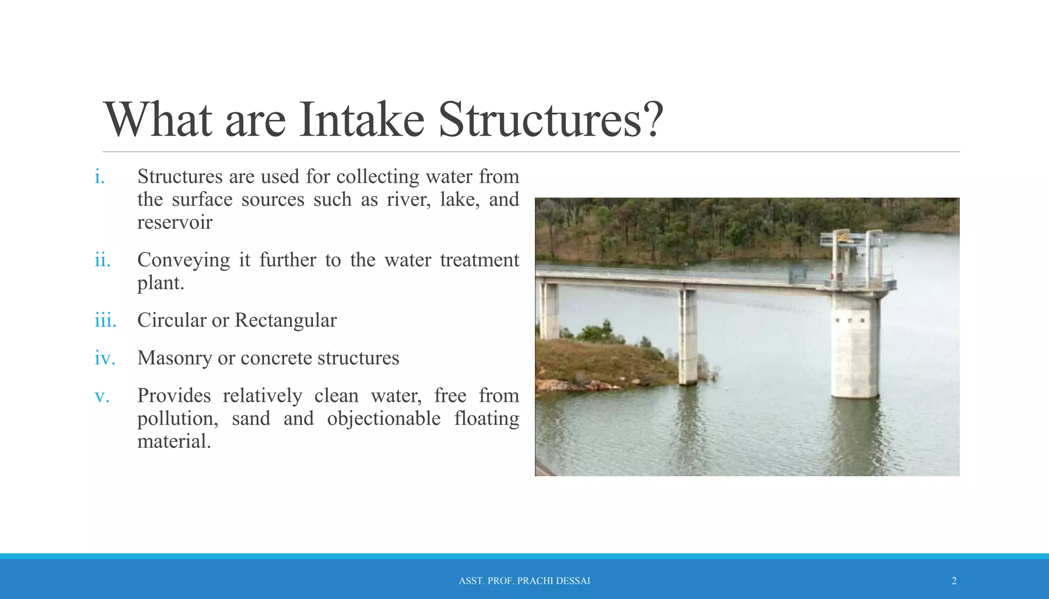
WATER SUPPLY ENGINEERING
ENVIRONMENT ENGINEERING I
INTAKE STRUCTURES
What are Intake Structures?
i. Structures are used for collecting water from
the surface sources such as river, lake, and
reservoir
ii. Conveying it further to the water treatment
plant.
iii. Circular or Rectangular
iv. Masonry or concrete structures
v. Provides relatively clean water, free from
pollution, sand and objectionable floating
material.
2
ASST. PROF. PRACHI DESSAI
Selecting Location Of Intake Structure
1. Provide purer water so that its treatment may become less exhaustive.
2. Heavy water currents should not strike the intake directly.
3. Placed where sufficient quantity of water remains available under all the circumstances.
4. Well connected by good type of roads.
5. Positioned to provide more water if required to do so.
6. Not be located in navigation channels, because water of such channels is generally polluted.
7. During floods in rivers, flood waters should not be concentrated towards the intake.
8. Not be located on the curve of the river. If there is no alternative then intake should be located on
the outer bank and not on the inner bank.
9. Located on up stream side of the town.
3
ASST. PROF. PRACHI DESSAI
Design of Intake
Intake should be designed on the basis of the following considerations:-
1. Should be sufficiently heavy, not be washed away by heavy water currents.
2. All the forces which are expected to work on intake should be carefully analyzed and intake
should be designed to withstand all these forces.
3. The foundation of the intake should be taken sufficiently deep - avoid overturning of the
structure.
4. Should not be constructed in a navigation channel as possible.
5. Strainers in the form of wire mesh should be provided on all the intake inlets. This will avoid
entry of large floating objects and fishes into the intake.
6. Should be of such size and so located that sufficient quantity of water can be obtained from the
intake in all circumstances.
4
ASST. PROF. PRACHI DESSAI
TYPES OF INTAKES
According to type of source
◦ River Intake
◦ Canal Intake
◦ Reservoir Intake
◦ Lake Intake
According to location
◦ Submerged Intake
◦ Exposed Intake
According to presence of water in the tower
◦ Wet Intake
◦ Dry Intake
5
ASST. PROF. PRACHI DESSAI
Intake constructed in the middle of the river Intake constructed on the banks on the river
6
ASST. PROF. PRACHI DESSAI
RIVER INTAKE WELL
i. Located - inside the river so that demands of
water are met with in all the seasons of the
year, or they may be located near the river
bank where a sufficient depth of water is
available.
ii. circular masonry tower
iii. Dia = 4 to 7 m
iv. constructed at such place from where
required quantity of water can be obtained
even in the dry period.
v. The water enters in the lower portion of the
intake known from penstocks.
7
ASST. PROF. PRACHI DESSAI
CANAL INTAKE WELL
i. The entry of water in the intake chamber takes
through coarse screen and the top of outlet pipe is
provided with fine screen.
ii. The inlet to outlet pipe is of bell-mouth shape with
perforations of the fine screen on its surface.
iii. The outlet valve is operated from the top and it
controls the entry of water into the outlet pipe
from where it is taken to the treatment plant.
8
ASST. PROF. PRACHI DESSAI
RESERVOIR INTAKE WELL
i. Intake pipes are located at different levels with
common vertical pipe.
ii. The valves of pipes are operated from the top and
they are installed in a valve room.
iii. Each intake pipe is provided with bell mouth entry
with perforations of fine screen on its
iv. surface. The outlet pipe is taken out through the
body of dam.
v. The location of intake pipes at different levels
ensures supply of water from a level lower than the
surface level of water.
9
ASST. PROF. PRACHI DESSAI
LAKE INTAKE
i. These intakes are constructed in the bed of
the lake below the water level; so as to
draw water in dry season also.
ii. As these intakes draw small quantity of
water, these are not used in big water
supply schemes or on rivers or reservoirs.
iii. Advantages - no obstruction to the
navigation, no danger from the floating
bodies and no trouble due to ice.
iv. Disadvantage - they are not easily
approachable for maintenance.
10
ASST. PROF. PRACHI DESSAI
Intake Structures
EXPOSED INTAKE STRUCTURES
i. Generally, a well or tower constructed near the
bank of a river/lake, or in some cases even away
from the river banks.
ii. These are more common due to ease in the
operation and maintenance.
SUBMERGED INTAKE STRUCTURES
i. Constructed entirely under water
ii. Simple concrete block or a rock filled timber crib
supporting the starting end of the withdrawal pipe
iii. Intake opening is covered by screen to prevent the
entry of debris, ice etc.
iv. Generally, do not obstruct navigation
v. The cost is lower compared to other options
vi. Limitation: Not easily accessible for cleaning and
repairing
11
ASST. PROF. PRACHI DESSAI
According to presence of water in the tower
WET INTAKE DRY INTAKE
12
ASST. PROF. PRACHI DESSAI
Wet Intake Towers
i. Concrete circular shell filled with water up to
the river / reservoir level keeping water level in
the intake practically the same as the level of
the sources.
ii. Has a vertical inside shaft connected to the
withdrawal pipe
iii. Controlled gate based openings are made in to
the outer concrete shell as well as, in to the
inside shaft.
iv. The withdrawal pipe may lie over the river bed
or may be in the form of tunnels below the
river bed
v. It is often known as Jack well and is most
commonly used.
13
ASST. PROF. PRACHI DESSAI
Dry Intake Towers
i. In case of dry intake there is no outer shell (as
in case of wet intake towers).
ii. Water enters through entry port directly into
the withdrawal conduits.
iii. When the entry ports are closed and there is no
water in the withdrawal conduit, a dry intake
tower will be subjected to greater buoyancy
forces.
iv. Hence it must be of heavier construction than
wet intake tower.
v. Operation of valves etc. are reasonably simple
in dry intake towers.
14
ASST. PROF. PRACHI DESSAI
Single Well vs Twin Well Intake
Twin Well Type Intakes consists of an inlet well, intake pipe, and a Jack Well. Intake pipe
connects inlet well with jack well with flow velocity <1.2 m/s.
Single Well Type Intakes, no inlet well & inlet pipe in needed, and opening or ports fitted with
bar screens are provided in the jack well itself.
15
ASST. PROF. PRACHI DESSAI
Recommended Readings
i. Mark J. Hammer; Water and Waste Water Technology; Prentice Hall of India.
ii. S. K. Garg; Water Supply Engineering; Khanna Publ.
iii. B. C. Punmia, A. K. Jain; Water Supply Engineering; Laxmi Publication.
iv. G. S. Birdie; Water Supply Engineering and Sanitary Engineering; Dhanpat Rai.
v. R. C. Rangwala; Water Supply Engineering, Charotar Publ. House.
ASST. PROF. PRACHI DESSAI 16

L3 -Intake Structures.ppt

  • 1.
    WATER SUPPLY ENGINEERING ENVIRONMENTENGINEERING I INTAKE STRUCTURES
  • 2.
    What are IntakeStructures? i. Structures are used for collecting water from the surface sources such as river, lake, and reservoir ii. Conveying it further to the water treatment plant. iii. Circular or Rectangular iv. Masonry or concrete structures v. Provides relatively clean water, free from pollution, sand and objectionable floating material. 2 ASST. PROF. PRACHI DESSAI
  • 3.
    Selecting Location OfIntake Structure 1. Provide purer water so that its treatment may become less exhaustive. 2. Heavy water currents should not strike the intake directly. 3. Placed where sufficient quantity of water remains available under all the circumstances. 4. Well connected by good type of roads. 5. Positioned to provide more water if required to do so. 6. Not be located in navigation channels, because water of such channels is generally polluted. 7. During floods in rivers, flood waters should not be concentrated towards the intake. 8. Not be located on the curve of the river. If there is no alternative then intake should be located on the outer bank and not on the inner bank. 9. Located on up stream side of the town. 3 ASST. PROF. PRACHI DESSAI
  • 4.
    Design of Intake Intakeshould be designed on the basis of the following considerations:- 1. Should be sufficiently heavy, not be washed away by heavy water currents. 2. All the forces which are expected to work on intake should be carefully analyzed and intake should be designed to withstand all these forces. 3. The foundation of the intake should be taken sufficiently deep - avoid overturning of the structure. 4. Should not be constructed in a navigation channel as possible. 5. Strainers in the form of wire mesh should be provided on all the intake inlets. This will avoid entry of large floating objects and fishes into the intake. 6. Should be of such size and so located that sufficient quantity of water can be obtained from the intake in all circumstances. 4 ASST. PROF. PRACHI DESSAI
  • 5.
    TYPES OF INTAKES Accordingto type of source ◦ River Intake ◦ Canal Intake ◦ Reservoir Intake ◦ Lake Intake According to location ◦ Submerged Intake ◦ Exposed Intake According to presence of water in the tower ◦ Wet Intake ◦ Dry Intake 5 ASST. PROF. PRACHI DESSAI
  • 6.
    Intake constructed inthe middle of the river Intake constructed on the banks on the river 6 ASST. PROF. PRACHI DESSAI
  • 7.
    RIVER INTAKE WELL i.Located - inside the river so that demands of water are met with in all the seasons of the year, or they may be located near the river bank where a sufficient depth of water is available. ii. circular masonry tower iii. Dia = 4 to 7 m iv. constructed at such place from where required quantity of water can be obtained even in the dry period. v. The water enters in the lower portion of the intake known from penstocks. 7 ASST. PROF. PRACHI DESSAI
  • 8.
    CANAL INTAKE WELL i.The entry of water in the intake chamber takes through coarse screen and the top of outlet pipe is provided with fine screen. ii. The inlet to outlet pipe is of bell-mouth shape with perforations of the fine screen on its surface. iii. The outlet valve is operated from the top and it controls the entry of water into the outlet pipe from where it is taken to the treatment plant. 8 ASST. PROF. PRACHI DESSAI
  • 9.
    RESERVOIR INTAKE WELL i.Intake pipes are located at different levels with common vertical pipe. ii. The valves of pipes are operated from the top and they are installed in a valve room. iii. Each intake pipe is provided with bell mouth entry with perforations of fine screen on its iv. surface. The outlet pipe is taken out through the body of dam. v. The location of intake pipes at different levels ensures supply of water from a level lower than the surface level of water. 9 ASST. PROF. PRACHI DESSAI
  • 10.
    LAKE INTAKE i. Theseintakes are constructed in the bed of the lake below the water level; so as to draw water in dry season also. ii. As these intakes draw small quantity of water, these are not used in big water supply schemes or on rivers or reservoirs. iii. Advantages - no obstruction to the navigation, no danger from the floating bodies and no trouble due to ice. iv. Disadvantage - they are not easily approachable for maintenance. 10 ASST. PROF. PRACHI DESSAI
  • 11.
    Intake Structures EXPOSED INTAKESTRUCTURES i. Generally, a well or tower constructed near the bank of a river/lake, or in some cases even away from the river banks. ii. These are more common due to ease in the operation and maintenance. SUBMERGED INTAKE STRUCTURES i. Constructed entirely under water ii. Simple concrete block or a rock filled timber crib supporting the starting end of the withdrawal pipe iii. Intake opening is covered by screen to prevent the entry of debris, ice etc. iv. Generally, do not obstruct navigation v. The cost is lower compared to other options vi. Limitation: Not easily accessible for cleaning and repairing 11 ASST. PROF. PRACHI DESSAI
  • 12.
    According to presenceof water in the tower WET INTAKE DRY INTAKE 12 ASST. PROF. PRACHI DESSAI
  • 13.
    Wet Intake Towers i.Concrete circular shell filled with water up to the river / reservoir level keeping water level in the intake practically the same as the level of the sources. ii. Has a vertical inside shaft connected to the withdrawal pipe iii. Controlled gate based openings are made in to the outer concrete shell as well as, in to the inside shaft. iv. The withdrawal pipe may lie over the river bed or may be in the form of tunnels below the river bed v. It is often known as Jack well and is most commonly used. 13 ASST. PROF. PRACHI DESSAI
  • 14.
    Dry Intake Towers i.In case of dry intake there is no outer shell (as in case of wet intake towers). ii. Water enters through entry port directly into the withdrawal conduits. iii. When the entry ports are closed and there is no water in the withdrawal conduit, a dry intake tower will be subjected to greater buoyancy forces. iv. Hence it must be of heavier construction than wet intake tower. v. Operation of valves etc. are reasonably simple in dry intake towers. 14 ASST. PROF. PRACHI DESSAI
  • 15.
    Single Well vsTwin Well Intake Twin Well Type Intakes consists of an inlet well, intake pipe, and a Jack Well. Intake pipe connects inlet well with jack well with flow velocity <1.2 m/s. Single Well Type Intakes, no inlet well & inlet pipe in needed, and opening or ports fitted with bar screens are provided in the jack well itself. 15 ASST. PROF. PRACHI DESSAI
  • 16.
    Recommended Readings i. MarkJ. Hammer; Water and Waste Water Technology; Prentice Hall of India. ii. S. K. Garg; Water Supply Engineering; Khanna Publ. iii. B. C. Punmia, A. K. Jain; Water Supply Engineering; Laxmi Publication. iv. G. S. Birdie; Water Supply Engineering and Sanitary Engineering; Dhanpat Rai. v. R. C. Rangwala; Water Supply Engineering, Charotar Publ. House. ASST. PROF. PRACHI DESSAI 16