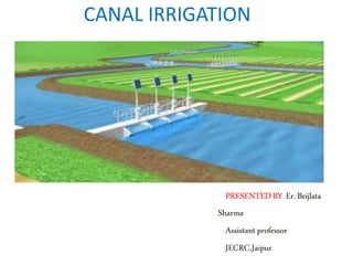
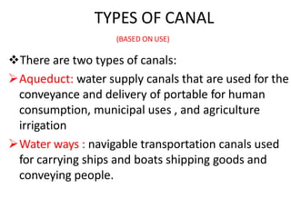
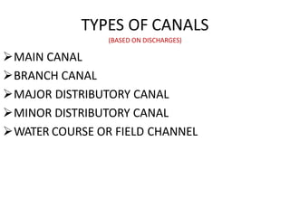
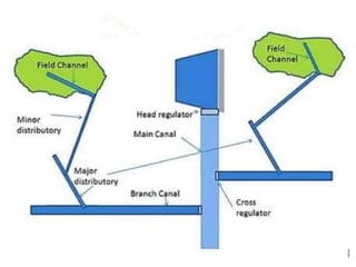
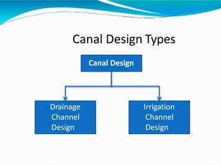
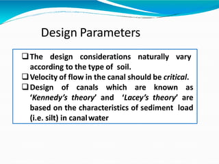
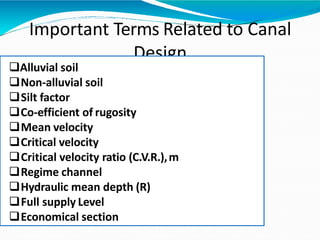
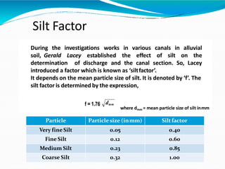
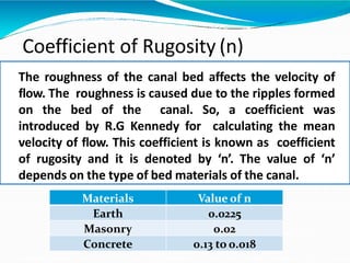
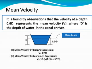
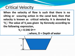
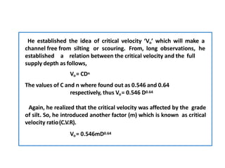
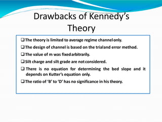
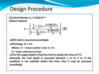
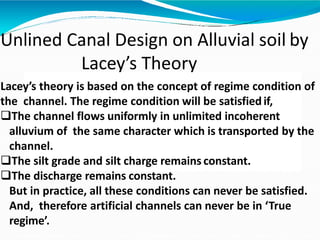
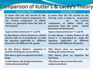
CANAL IRRIGATION
PRESENTEDBY Er.Brijlata
Sharma
Assistantprofessor
JECRC,Jaipur
DEFINITION
An artificial channel filled with water and designed
for navigation , or irrigating land, etc.
An artificial water course or extensively modified
natural channel used for inland water transport
and/or the control and diversion of water for
drainage or irrigation
TYPES OF CANAL
(BASED ON USE)
There are two types of canals:
Aqueduct: water supply canals that are used for the
conveyance and delivery of portable for human
consumption, municipal uses , and agriculture
irrigation
Water ways : navigable transportation canals used
for carrying ships and boats shipping goods and
conveying people.
TYPES OF CANALS
(BASED ON DISCHARGES)
MAIN CANAL
BRANCH CANAL
MAJOR DISTRIBUTORY CANAL
MINOR DISTRIBUTORY CANAL
WATER COURSE OR FIELD CHANNEL
MAIN CANALS
Main canal takes of directly from the
upstream side of weir head works or dam.
Usually no direct cultivation is proposed.
BRANCH CANAL
All off takes from main canal with head discharge of
14-15 cumecs and above are termed as branch
canals.
Acts as feeder channel for major distributaries.
 MAJOR DISTRIDUTARY:
 All off takes from main canal or branch canal with head
discharge from 0.028 to 15 cumecs are termed as major
distributaries .
 MINOR DISTRIBUTARY:
 All off takes taking off from a measure distributary carrying
discharge less than 0.25 cumec are termed as minor
distributaries.
 WATER COURSE
 Small channels which carry water from the outlets of a major
or minor distributary or a branch channel to the fields to be
irrigated.
TYPES OF CANALS
(Based on lining being provided or not)
1.Lined canals
2.Unlined canals
SHAPES OF CANAL
1. CIRCULAR SHAPE
2. TRIANGULAR SHAPE
3. TRIPEZOIDAL SHAPE
4. PARABOLIC SHAPE
5. RECTANGULAR SHAPE
LINED CANAL
A Lined canals is provided with a lining of
imprevious material on its bed and banks to
prevent the seepage of water.
Types of canal lining
1. Concrete lining
2. Short crete lining
3. Brick or burnt clay tile lining
4. Boulder lining
Unlined canal
An unlined canal is the one which as it bed
and banks made of natural soil through which
it is constructed and not provided with a lining
of imprevious material.
Disadvantages of unlined canal
• Water velocities higher then 0.7m/sec or not tolerable
because of erosion . The low operating velocities requires
large cross-section area.
• High seepage and conveyance water losses result in water
logging of adjacent land.
• Danger of canal bank breakage caused by overtopping ,
erosion and animal burrowing.
• Profuse growth of aquatic weeds retards the flow and causes
heavy maintenances cost.
ILL-EFFECT OF WATER LOGGING
• Water seeping from canal down to the soil below may , head
times , raise the ground water very close to the ground level .
• This may result in blocking all the voids in the soil and
obstructing the plant roots to breathe.
• Normal cultivation operations , such as tilling , ploughing, etc.
cannot be easily carried out in wet soils.
Irrigation canal layout
• As for a possible, curves should be avoided in the alignment
of canals.
• The curves lead to disturbance of flow and a tendency to silt
on the inner bend and scour the toe of the outer bend.
• If curves have to be provided ;they should be as gentle as
possible.
• The permissible minimum radius of curvature for a channel
curve is shorter for lined canals than unlined ones
• The alignment should be such that the cutting and filling of
earth rock should be balanced , as far as possible.
TYPES OF DRAINAGE SYSTEM
Surface drainage
These constitute open ditches , field drains,
proper land grading and related structures.
Land grading , or properly sloping the land
towards the field drains, is an important
method for effecting surface drainage.
TYPES OF DRAINAGE SYSTEM
Sub surface drainage
These are installed to lower the water table
Consist of underground pipes which collect
water and remove it through a network of
such pipes.
UNLINED CANAL DESIGN
Canal Design
Drainage
Channel
Design
Irrigation
Channel
Design
Canal Design Types
Design Parameters
The design considerations naturally vary
according to the type of soil.
Velocity of flow in the canal should be critical.
Design of canals which are known as
‘Kennedy’s theory’ and ‘Lacey’s theory’ are
based on the characteristics of sediment load
(i.e. silt) in canalwater
Important Terms Related to Canal
Design
Alluvial soil
Non-alluvial soil
Silt factor
Co-efficient of rugosity
Mean velocity
Critical velocity
Critical velocity ratio (C.V.R.),m
Regime channel
Hydraulic mean depth (R)
Full supply Level
Economical section
Alluvial Soil
The soil which is formed by the continuous deposition of
silt is known as alluvial soil. The river carries heavy
charge of silt in rainy season. When the river overflows
its banks during the flood, the silt particles get
deposited on the adjoining areas. This deposition of silt
continues year after year. This type of soil is found in
deltaic region of a river. This soil is permeable and soft
and very fertile. The river passing through this type of
soil has a tendency to change its course.
Non-alluvial Soil
The soil which is formed by the disintegration of
rock formations is known as non-alluvial soil. It
is found in the mountainous region of a river.
The soil is hard and impermeable in nature. This
is not fertile. The river passing through this type
of soil has no tendency to change its course.
Silt Factor
During the investigations works in canals in alluvial
soil, Gerald Lacey established the
various
effect of silt on the
determination of discharge and the canal section. So, Lacey
introduced a factor which is known as ‘siltfactor’.
It depends on the mean particle size of silt. It is denoted by ‘f’. The
silt factor is determined by the expression,
f = 1.76 dmm
where dmm = mean particle size of silt inmm
Particle Particle size (inmm) Silt factor
Very fine Silt 0.05 0.40
Fine Silt 0.12 0.60
Medium Silt 0.23 0.85
Coarse Silt 0.32 1.00
Coefficient of Rugosity (n)
The roughness of the canal bed affects the velocity of
flow. The roughness is caused due to the ripples formed
on the bed of the canal. So, a coefficient was
introduced by R.G Kennedy for calculating the mean
velocity of flow. This coefficient is known as coefficient
of rugosity and it is denoted by ‘n’. The value of ‘n’
depends on the type of bed materials of the canal.
Materials Value of n
Earth 0.0225
Masonry 0.02
Concrete 0.13 to 0.018
D
0.6 D
Mean Velocity
It is found by observations that the velocity at a depth
0.6D represents the mean velocity (V), where ‘D’ is
the depth of water in the canal orriver.
(a) Mean Velocity By Chezy’s Expression:
V= C√RS
(b) Mean Velocity By Manning’s Expression:
V=(1/n)x(R^⅔)x(S^ ⅟₂)
Mean Depth
Critical Velocity
When the velocity of flow is such that there is no
silting or scouring action in the canal bed, then that
velocity is known as critical velocity. It is denoted by
‘Vo’. The value of Vowas given by Kennedy according to
the following expression,
Vo= 0.546 D0.64
; where, D = Depth of water
D
Critical Velocity Ratio
(C.V.R.)
The ratio of mean velocity ‘V’ to the critical velocity ‘V₀’
is known as critical velocity ratio (C.V.R.). It is denoted
by ‘m’ i.e.
C.V.R. (m)=V/V₀
When m = 1, there will be no silting or scouring
When m > 1, scouring will occur
When m < 1, silting will occur
So , by finding the value of m, the condition of the canal
can be predicted whether it will have silting or scouring
Regime Channel
When the character of the bed and bank
materials of the channel are same as that of the
transported materials and when the silt charge
and silt grade are constant, then the channel is
said to be in its regime and the channel is called
regime channel. This ideal condition is not
practicallypossible.
Hydraulic Mean Depth
The ratio of the cross-sectional area of flow to
the wetted perimeter of the channel is known
as hydraulic mean depth. It is generally denoted
by R.
R = A/P
Where,
A = Cross-sectionalarea
P = Wettedperimeter
Full Supply Level
The maximum capacity of the canal for which it is
designed, is known as full supply discharge. The
water level of the canal corresponding to the full
supply discharge is known as full supply level
(F.S.L).
FSL
Cutting Area Balancingdepth
Economical Section
If a canal section is such that the earth obtained from cutting (i.e.
excavation) can be fully utilized in forming the banks, then that
section is known as economical section. Again, the discharge will be
maximum with minimum cross-section area. Here, no extra earth is
required from borrow pit and no earth is in excess to form the spoil
bank. This condition can only arise in case of partial cutting and
partial banking. Sometimes, this condition is designated as
balancing of cutting and banking. Here, the depth of cutting is
called balancingdepth.
Filling Area
Unlined Canal Design on Alluvial soil by
Kennedy’s Theory
After long investigations, R.G Kennedy arrived at a theory which states
that, the silt carried by flowing water in a channel is kept in suspension
by the vertical component of eddy current which is formed over the
entire bed width of the channel and the suspended silt rises up gently
towards thesurface.
The following assumptions are made in support of his theory:
 The eddy current is developed due to the roughness of thebed.
 The quality of the suspended silt is proportional to bedwidth.
 It is applicable to those channels which are flowing through
the bed consisting of sandy silt or same grade of silt.
 It is applicable to those channels which are flowing through the
bed consisting of sandy silt or same grade of silt.
He established the idea of critical velocity ‘Vo’ which will make a
channel free from silting or scouring. From, long observations, he
established a relation between the critical velocity and the full
supply depth as follows,
Vo= CDn
The values of C and n where found out as 0.546 and 0.64
respectively, thus Vo= 0.546 D0.64
Again, he realized that the critical velocity was affected by the grade
of silt. So, he introduced another factor (m) which is known as critical
velocity ratio(C.V.R).
Vo= 0.546mD0.64
Drawbacks of Kennedy’s
Theory
The theory is limited to average regime channelonly.
The design of channel is based on the trialand error method.
The value of m was fixedarbitrarily.
Silt charge and silt grade are notconsidered.
 There is no equation for determining the bed slope and it
depends on Kutter’s equation only.
The ratio of ‘B’ to ‘D’ has no significance in his theory.
Critical Velocity, Vo= 0.546 D0.64
Mean Velocity
B/D ratio is assumedaccordingly
Discharge, Q = AV
Where, A = Cross-section area in m2,
V = mean velocity inm/sec
The full supply depth is fixed by trial to satisfy the value of‘m’.
Generally, the trial depth is assumed between 1 m to 2 m. If the
condition is not satisfied within this limit, then it may be assumed
accordingly.
Design Procedure
Unlined Canal Design on Alluvial soil by
Lacey’s Theory
Lacey’s theory is based on the concept of regime condition of
the channel. The regime condition will be satisfiedif,
The channel flows uniformly in unlimited incoherent
alluvium of the same character which is transported by the
channel.
The silt grade and silt charge remains constant.
The discharge remains constant.
But in practice, all these conditions can never be satisfied.
And, therefore artificial channels can never be in ‘True
regime’.
Initial Regime and Final Regime
When only the bed slope of a channel varies due to
dropping of silt , and its cross-section or wetted perimeter
remains unaffected, even them the channel can exhibit
‘no silting no scouring’ properties, called INITIAL REGIME.
IF there is no resistance from the sides, and all the
variables such as perimeter, depth, slope etc. are equally
free to vary and get adjusted according to discharge and
silt grade, then the channel is said to have achieved
permanent stability, called FINAL REGIME.
Design Procedure
 Calculate the velocity from equation
Where, Q is discharge in cumecs,
V is velocity in m/s
f is silt factor
 Workout the hydraulic mean depth (R) from the equation
 Compute area(A) of channel section by using
 Compute the wetted perimeter, P
Knowing these values, the channel section is known; and finally
the bed slope (S) is determined by the equation
 B/D ratio of channel is assumed accordingly.
Drawbacks of Lacey’s Theory
 The conceptof true regimeis theoretical and con not be
achieved practically.
 The various equations are derived by considering the silt factor f
which is not at allconstant.
 The concentration of silt is not taken intoaccount.
 Silt grade and silt charge is not taken intoaccount.
 The equations are empirical and based on the available data from a
particular type of channel. So, it may not be true for a different
type of channel.
 The characteristics of regime channel may not be same for allcases.
Kennedy’sTheory Lacey’s Theory
It states that the silt carried by the
flowing water is kept in suspension by
the vertical component of eddies
which are generated from the bed of
thechannel.
It states that the silt carried by the
flowing water is kept in suspension
by the vertical
component of eddies which are
generated from the entire wetted
perimeter of thechannel.
Itgivesrelation between ‘V’ and ‘D’. Itgivesrelationbetween ‘V’ and ‘R’.
In this theory, a factor known as critical
velocity ratio ‘m’ is introduced to make
the equation applicable to different
channels with different silt grades
In this theory, a factor known as silt
factor ‘f ’ is introduced to make the
equation applicable to different
channels with different silt grades.
In this theory, Kutter’s equation is
used for finding the meanvelocity.
This theory gives an equation for
finding the meanvelocity.
This theory gives no equation forbed
slope.
This theory gives an equation for
bed slope.
In this theory, the design is based on
trial and errormethod.
This theory does not involve trial
anderrormethod.
Comparison of Kutter’s & Lacey’s Theory
conclusions
Explicit design equation and sections shape co
efficient have been present for the minimum cost
design of lined canal of triangular, rectangular
trapezoidal& circular shapes .
These equation &co efficient have been
obtained by applying the nonlinear optimization
technique

Canal design

  • 1.
  • 2.
    DEFINITION An artificial channelfilled with water and designed for navigation , or irrigating land, etc. An artificial water course or extensively modified natural channel used for inland water transport and/or the control and diversion of water for drainage or irrigation
  • 3.
    TYPES OF CANAL (BASEDON USE) There are two types of canals: Aqueduct: water supply canals that are used for the conveyance and delivery of portable for human consumption, municipal uses , and agriculture irrigation Water ways : navigable transportation canals used for carrying ships and boats shipping goods and conveying people.
  • 4.
    TYPES OF CANALS (BASEDON DISCHARGES) MAIN CANAL BRANCH CANAL MAJOR DISTRIBUTORY CANAL MINOR DISTRIBUTORY CANAL WATER COURSE OR FIELD CHANNEL
  • 5.
    MAIN CANALS Main canaltakes of directly from the upstream side of weir head works or dam. Usually no direct cultivation is proposed.
  • 7.
    BRANCH CANAL All offtakes from main canal with head discharge of 14-15 cumecs and above are termed as branch canals. Acts as feeder channel for major distributaries.
  • 9.
     MAJOR DISTRIDUTARY: All off takes from main canal or branch canal with head discharge from 0.028 to 15 cumecs are termed as major distributaries .  MINOR DISTRIBUTARY:  All off takes taking off from a measure distributary carrying discharge less than 0.25 cumec are termed as minor distributaries.  WATER COURSE  Small channels which carry water from the outlets of a major or minor distributary or a branch channel to the fields to be irrigated.
  • 10.
    TYPES OF CANALS (Basedon lining being provided or not) 1.Lined canals 2.Unlined canals
  • 11.
    SHAPES OF CANAL 1.CIRCULAR SHAPE 2. TRIANGULAR SHAPE 3. TRIPEZOIDAL SHAPE 4. PARABOLIC SHAPE 5. RECTANGULAR SHAPE
  • 12.
    LINED CANAL A Linedcanals is provided with a lining of imprevious material on its bed and banks to prevent the seepage of water.
  • 13.
    Types of canallining 1. Concrete lining 2. Short crete lining 3. Brick or burnt clay tile lining 4. Boulder lining
  • 14.
    Unlined canal An unlinedcanal is the one which as it bed and banks made of natural soil through which it is constructed and not provided with a lining of imprevious material.
  • 15.
    Disadvantages of unlinedcanal • Water velocities higher then 0.7m/sec or not tolerable because of erosion . The low operating velocities requires large cross-section area. • High seepage and conveyance water losses result in water logging of adjacent land. • Danger of canal bank breakage caused by overtopping , erosion and animal burrowing. • Profuse growth of aquatic weeds retards the flow and causes heavy maintenances cost.
  • 17.
    ILL-EFFECT OF WATERLOGGING • Water seeping from canal down to the soil below may , head times , raise the ground water very close to the ground level . • This may result in blocking all the voids in the soil and obstructing the plant roots to breathe. • Normal cultivation operations , such as tilling , ploughing, etc. cannot be easily carried out in wet soils.
  • 18.
    Irrigation canal layout •As for a possible, curves should be avoided in the alignment of canals. • The curves lead to disturbance of flow and a tendency to silt on the inner bend and scour the toe of the outer bend. • If curves have to be provided ;they should be as gentle as possible. • The permissible minimum radius of curvature for a channel curve is shorter for lined canals than unlined ones • The alignment should be such that the cutting and filling of earth rock should be balanced , as far as possible.
  • 19.
    TYPES OF DRAINAGESYSTEM Surface drainage These constitute open ditches , field drains, proper land grading and related structures. Land grading , or properly sloping the land towards the field drains, is an important method for effecting surface drainage.
  • 20.
    TYPES OF DRAINAGESYSTEM Sub surface drainage These are installed to lower the water table Consist of underground pipes which collect water and remove it through a network of such pipes.
  • 21.
  • 22.
  • 23.
    Design Parameters The designconsiderations naturally vary according to the type of soil. Velocity of flow in the canal should be critical. Design of canals which are known as ‘Kennedy’s theory’ and ‘Lacey’s theory’ are based on the characteristics of sediment load (i.e. silt) in canalwater
  • 24.
    Important Terms Relatedto Canal Design Alluvial soil Non-alluvial soil Silt factor Co-efficient of rugosity Mean velocity Critical velocity Critical velocity ratio (C.V.R.),m Regime channel Hydraulic mean depth (R) Full supply Level Economical section
  • 25.
    Alluvial Soil The soilwhich is formed by the continuous deposition of silt is known as alluvial soil. The river carries heavy charge of silt in rainy season. When the river overflows its banks during the flood, the silt particles get deposited on the adjoining areas. This deposition of silt continues year after year. This type of soil is found in deltaic region of a river. This soil is permeable and soft and very fertile. The river passing through this type of soil has a tendency to change its course.
  • 26.
    Non-alluvial Soil The soilwhich is formed by the disintegration of rock formations is known as non-alluvial soil. It is found in the mountainous region of a river. The soil is hard and impermeable in nature. This is not fertile. The river passing through this type of soil has no tendency to change its course.
  • 27.
    Silt Factor During theinvestigations works in canals in alluvial soil, Gerald Lacey established the various effect of silt on the determination of discharge and the canal section. So, Lacey introduced a factor which is known as ‘siltfactor’. It depends on the mean particle size of silt. It is denoted by ‘f’. The silt factor is determined by the expression, f = 1.76 dmm where dmm = mean particle size of silt inmm Particle Particle size (inmm) Silt factor Very fine Silt 0.05 0.40 Fine Silt 0.12 0.60 Medium Silt 0.23 0.85 Coarse Silt 0.32 1.00
  • 28.
    Coefficient of Rugosity(n) The roughness of the canal bed affects the velocity of flow. The roughness is caused due to the ripples formed on the bed of the canal. So, a coefficient was introduced by R.G Kennedy for calculating the mean velocity of flow. This coefficient is known as coefficient of rugosity and it is denoted by ‘n’. The value of ‘n’ depends on the type of bed materials of the canal. Materials Value of n Earth 0.0225 Masonry 0.02 Concrete 0.13 to 0.018
  • 29.
    D 0.6 D Mean Velocity Itis found by observations that the velocity at a depth 0.6D represents the mean velocity (V), where ‘D’ is the depth of water in the canal orriver. (a) Mean Velocity By Chezy’s Expression: V= C√RS (b) Mean Velocity By Manning’s Expression: V=(1/n)x(R^⅔)x(S^ ⅟₂) Mean Depth
  • 30.
    Critical Velocity When thevelocity of flow is such that there is no silting or scouring action in the canal bed, then that velocity is known as critical velocity. It is denoted by ‘Vo’. The value of Vowas given by Kennedy according to the following expression, Vo= 0.546 D0.64 ; where, D = Depth of water D
  • 31.
    Critical Velocity Ratio (C.V.R.) Theratio of mean velocity ‘V’ to the critical velocity ‘V₀’ is known as critical velocity ratio (C.V.R.). It is denoted by ‘m’ i.e. C.V.R. (m)=V/V₀ When m = 1, there will be no silting or scouring When m > 1, scouring will occur When m < 1, silting will occur So , by finding the value of m, the condition of the canal can be predicted whether it will have silting or scouring
  • 32.
    Regime Channel When thecharacter of the bed and bank materials of the channel are same as that of the transported materials and when the silt charge and silt grade are constant, then the channel is said to be in its regime and the channel is called regime channel. This ideal condition is not practicallypossible.
  • 33.
    Hydraulic Mean Depth Theratio of the cross-sectional area of flow to the wetted perimeter of the channel is known as hydraulic mean depth. It is generally denoted by R. R = A/P Where, A = Cross-sectionalarea P = Wettedperimeter
  • 34.
    Full Supply Level Themaximum capacity of the canal for which it is designed, is known as full supply discharge. The water level of the canal corresponding to the full supply discharge is known as full supply level (F.S.L). FSL
  • 35.
    Cutting Area Balancingdepth EconomicalSection If a canal section is such that the earth obtained from cutting (i.e. excavation) can be fully utilized in forming the banks, then that section is known as economical section. Again, the discharge will be maximum with minimum cross-section area. Here, no extra earth is required from borrow pit and no earth is in excess to form the spoil bank. This condition can only arise in case of partial cutting and partial banking. Sometimes, this condition is designated as balancing of cutting and banking. Here, the depth of cutting is called balancingdepth. Filling Area
  • 36.
    Unlined Canal Designon Alluvial soil by Kennedy’s Theory After long investigations, R.G Kennedy arrived at a theory which states that, the silt carried by flowing water in a channel is kept in suspension by the vertical component of eddy current which is formed over the entire bed width of the channel and the suspended silt rises up gently towards thesurface. The following assumptions are made in support of his theory:  The eddy current is developed due to the roughness of thebed.  The quality of the suspended silt is proportional to bedwidth.  It is applicable to those channels which are flowing through the bed consisting of sandy silt or same grade of silt.  It is applicable to those channels which are flowing through the bed consisting of sandy silt or same grade of silt.
  • 37.
    He established theidea of critical velocity ‘Vo’ which will make a channel free from silting or scouring. From, long observations, he established a relation between the critical velocity and the full supply depth as follows, Vo= CDn The values of C and n where found out as 0.546 and 0.64 respectively, thus Vo= 0.546 D0.64 Again, he realized that the critical velocity was affected by the grade of silt. So, he introduced another factor (m) which is known as critical velocity ratio(C.V.R). Vo= 0.546mD0.64
  • 38.
    Drawbacks of Kennedy’s Theory Thetheory is limited to average regime channelonly. The design of channel is based on the trialand error method. The value of m was fixedarbitrarily. Silt charge and silt grade are notconsidered.  There is no equation for determining the bed slope and it depends on Kutter’s equation only. The ratio of ‘B’ to ‘D’ has no significance in his theory.
  • 39.
    Critical Velocity, Vo=0.546 D0.64 Mean Velocity B/D ratio is assumedaccordingly Discharge, Q = AV Where, A = Cross-section area in m2, V = mean velocity inm/sec The full supply depth is fixed by trial to satisfy the value of‘m’. Generally, the trial depth is assumed between 1 m to 2 m. If the condition is not satisfied within this limit, then it may be assumed accordingly. Design Procedure
  • 40.
    Unlined Canal Designon Alluvial soil by Lacey’s Theory Lacey’s theory is based on the concept of regime condition of the channel. The regime condition will be satisfiedif, The channel flows uniformly in unlimited incoherent alluvium of the same character which is transported by the channel. The silt grade and silt charge remains constant. The discharge remains constant. But in practice, all these conditions can never be satisfied. And, therefore artificial channels can never be in ‘True regime’.
  • 41.
    Initial Regime andFinal Regime When only the bed slope of a channel varies due to dropping of silt , and its cross-section or wetted perimeter remains unaffected, even them the channel can exhibit ‘no silting no scouring’ properties, called INITIAL REGIME. IF there is no resistance from the sides, and all the variables such as perimeter, depth, slope etc. are equally free to vary and get adjusted according to discharge and silt grade, then the channel is said to have achieved permanent stability, called FINAL REGIME.
  • 42.
    Design Procedure  Calculatethe velocity from equation Where, Q is discharge in cumecs, V is velocity in m/s f is silt factor  Workout the hydraulic mean depth (R) from the equation  Compute area(A) of channel section by using
  • 43.
     Compute thewetted perimeter, P Knowing these values, the channel section is known; and finally the bed slope (S) is determined by the equation  B/D ratio of channel is assumed accordingly.
  • 44.
    Drawbacks of Lacey’sTheory  The conceptof true regimeis theoretical and con not be achieved practically.  The various equations are derived by considering the silt factor f which is not at allconstant.  The concentration of silt is not taken intoaccount.  Silt grade and silt charge is not taken intoaccount.  The equations are empirical and based on the available data from a particular type of channel. So, it may not be true for a different type of channel.  The characteristics of regime channel may not be same for allcases.
  • 45.
    Kennedy’sTheory Lacey’s Theory Itstates that the silt carried by the flowing water is kept in suspension by the vertical component of eddies which are generated from the bed of thechannel. It states that the silt carried by the flowing water is kept in suspension by the vertical component of eddies which are generated from the entire wetted perimeter of thechannel. Itgivesrelation between ‘V’ and ‘D’. Itgivesrelationbetween ‘V’ and ‘R’. In this theory, a factor known as critical velocity ratio ‘m’ is introduced to make the equation applicable to different channels with different silt grades In this theory, a factor known as silt factor ‘f ’ is introduced to make the equation applicable to different channels with different silt grades. In this theory, Kutter’s equation is used for finding the meanvelocity. This theory gives an equation for finding the meanvelocity. This theory gives no equation forbed slope. This theory gives an equation for bed slope. In this theory, the design is based on trial and errormethod. This theory does not involve trial anderrormethod. Comparison of Kutter’s & Lacey’s Theory
  • 46.
    conclusions Explicit design equationand sections shape co efficient have been present for the minimum cost design of lined canal of triangular, rectangular trapezoidal& circular shapes . These equation &co efficient have been obtained by applying the nonlinear optimization technique