Downloaded 17 times
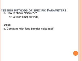
![TECHNICAL SPECIFICATION:
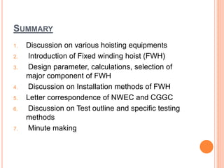
Parameter Values Parameter Values
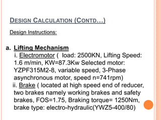
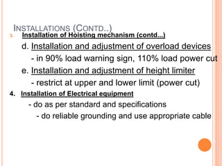
1. Lifting load 2500KN 9. Motor YZPF315M2-8 110kw
(S3 40%) 741 rpm
2. Lifting height 71m 10. Brake YWZ5-400/80
[M]b=630-1250Nm
3. Lifting speed 1.6/3.2 m/min 11. Open gear m=25, Z2=99, Z1=19,
i=5.211
4. Drum
diameter
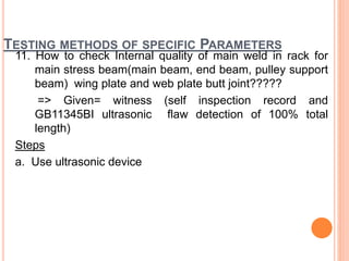
1500mm 12. Load meter ZHY-30t
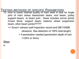
5. Job level Q2-light 13. Encoder AVM58
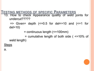
6. Pulley ratio 6 14. Limit switch:
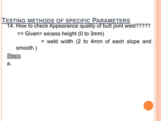
(Mech/Electrical)
QGX-C
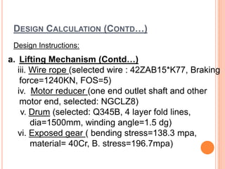
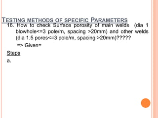
7. Wire rope 42ZAB15*K7+IWRC-
1770ZS
15. Power Supply AC400V/230V
8. Reducer QJRS-D710-80 i=82.05 16. Control Source AC230V/DC24V](https://image.slidesharecdn.com/fixedhoisting-181206055302/85/Hoisting-equipment-inspection-presentation-13-320.jpg)
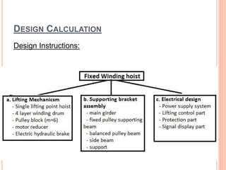


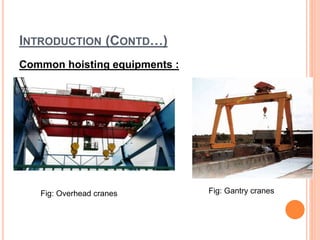
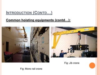
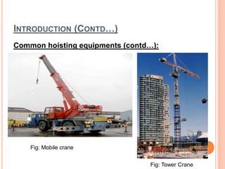
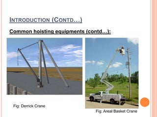
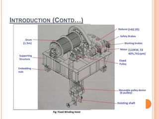
This document discusses the testing and inspection of a fixed winding hoist (FWH) used for lifting a surge shaft gate. It includes: 1. An introduction to hoisting equipment and the technical specifications of the FWH being discussed. 2. The design methodology and components of the FWH. 3. Previous comments and feedback from consultants on the design. 4. The proposed acceptance testing process and equipment needed. 5. Methods for inspecting specific parameters of the FWH like material properties, weld quality, and dimensional tolerances.


