
More Related Content
What's hot
What's hot (20)
Similar to FinalReport_Group10
Similar to FinalReport_Group10 (20)
FinalReport_Group10
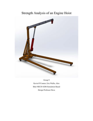
- 1. Strength Analysis of an Engine Hoist Group 9 Kevin O’Connor, Eric Wallis, Alex Blair MECH 4200-Simulation Based Design Professor Duva
- 2. Executive Summary The process of reviewing and redesigning the engine hoist was done by a team of three engineers in the mechanical department. A design for a moveable and weight adjustable engine hoist was brought to us so that we would run analysis on it and make sure the engine hoist was safe and would work as we intended it to. We had to test the extreme cases for each configuration to ensure that no one would get harmed while using our product. This was not the case and many components had to be redesigned. The redesigned engine hoist passed the analysis in every extreme case, while maintaining a minimum factor of safety of 1.5 for each component in the assembly. You will be able to see in this report how we started with the original design, found out the errors, corrected them, and reanalyzed them until we were sure that the new design would be safe and do its job. We certify that this engine hoist will perform as it is intended. Kevin O’Connor, Eric Wallis, Alex Blair
- 3. Table of Contents Introduction..................................................................................................................................................1 Design Requirements...................................................................................................................................2 Analysis and Redesign..............................................................................................................................2 Free Body Diagrams .................................................................................................................................8 Governing Equations for Horizontal Loading: ...................................................................................11 Governing Equations when there is a 17” extension:.......................................................................11 Governing Equations when there is NO extension:..........................................................................12 Governing Equations for Horizontal Loading when adjustable bar is at second hole:....................12 Governing Equations for Horizontal Loading when Adjustable Bar is at furthest hole:..................13 Hand Calculations...................................................................................................................................14 Bolt Forces:.........................................................................................................................................17 FE analysis...................................................................................................................................................24 Tabulated Simulation Results ................................................................................................................25 2 Ton Tabulated Results Initial ..........................................................................................................25 1 Ton Tabulated Results Initial: .........................................................................................................25 0.5 Ton Tabulated Results Initial .......................................................................................................26 2 Ton Tabulated Results Redesign.....................................................................................................27 1 Ton Tabulated Results Redesign.....................................................................................................27 0.5 Ton Tabulated Results Redesign..................................................................................................28 Discussion and Conclusion.........................................................................................................................29 Half ton (Alex Blair)............................................................................................................................29 One Ton (Kevin O’Connor) .................................................................................................................29 Two Ton (Eric Wallis)..........................................................................................................................30 Drawings.....................................................................................................................................................32 Assembly/Sub-Assemblies BOM’s.........................................................................................................32 Original Design Drawings.......................................................................................................................37 Redesign Drawings.................................................................................................................................53 Sub-Assembly Drawings.........................................................................................................................59 Recommendations .....................................................................................................................................62 Appendix.....................................................................................................................................................63 References..................................................................................................................................................64
- 4. 1 Introduction Our team of engineers was tasked with confirming the design for a moveable and adjustable engine hoist that our company plans to sell. It is capable of adjusting to three different settings, depending on the weight of the engine you wish to lift. There is a half-ton, one ton, and two ton configuration. In order to move between configurations just loosen the bolt and move it to the configuration that your application requires, retighten the bolt. Once you have the hoist set to the configuration you need, you can start to use the hoist. It was during the initial design review that the team decided to break up the analysis of the engine hoist so that we were all focusing on one configuration each. We all began to create free body diagrams of the design based on our configuration, as well as a 3d CAD model in SolidWorks. With the free body diagrams complete, we began to analyze each configuration of the engine hoist to confirm it will work as we intended. Unfortunately for all of our results it showed that the initial design was not sufficient, some components were fine but still required us engineers to redesign many of them. We wanted the general shape and size to stay the same as the original design, but now it will be able to safely lift any engine that falls within the hoists capabilities. The redesigned hoist is capable of going from its lowest point to 17” higher than the low point. The engine hoist will also be moveable so that it can be stowed away when it is not in use, making it ideal for an at home mechanic. Below you will be able to see all of the components that were in the original design as well as the components that we redesigned. We also included Stress, Displacement, and Factor of Safety plots to view on both the original and the redesigned parts for the hoist. We have also shown our results in a table format to show which components failed and what they are like now that they are redesigned. We also backed up all of the simulation work we did with hand calculations to confirm our findings.
- 5. 2 Design Requirements The product that we have analyzed and redesigned is moveable and adjustable engine hoist that is capable of lifting engines up to two tons. The adjustable hoist has three different settings where each setting represents the weight that it is capable of lifting. There is a half-ton setting, a one ton setting, and a two ton setting. You must make sure that you have the hoist safely connected at the correct setting before lifting an engine. You can change the configuration by loosening the bolt on the boom assembly up top, and then moving it to the correct location. The half-ton configuration is the closest to the end of the tubing, the one ton is in the middle, and the two ton is the one closest to the post. After you have put the bolt in the correct location, securely tighten the bolt and you are good to go. The configuration must be correct or the engine hoist could fail. The maximum amount of weight for the 1 ton configuration is exactly 1 ton or 2000 lbs, anything less than that will be fine however anything more than that will likely end up damaging some of the parts that make up the engine hoist. The engine hoist is capable of going from its lowest point and then raising that engine seventeen inches above that point. The great part about this engine hoist is that even though it’s moveable, it can still life a 4000 lb engine 17”. The hoist called for strong steel alloys as well as lower grade 1020 steel. Analysis and Redesign The two ton loading case was by far the worst case scenario when it came to all design parameters. Both the horizontal and extension configuration resulted in the highest amount of loading, deflection, and stress on all the parts. From these stresses a matrix was made in Excel to compare the factor of safeties to the design criteria of 1.5 for each part. From the matrix it can be seen that every part except for 10009 failed the initial loading conditions. For the purpose of this redesign, a factor of safety of 1.5 was the criteria the design team used to evaluate necessary changes and modifications to all parts. Every part except part 10007 had a factor of safety that could be easily improved on by simply changing materials and thicknesses. However part 10007 had such a low factor of safety in the worst loading conditions that a complete redesign of the part was necessary. An increase to the thickness of the material would not make much of an impact on the factor of safety of this part. The issues with part 10007 and the solutions will be addressed below. For the purpose of this analysis parts 10011, 10012, 10016, 50014 and 50015 are excluded. Parts 10011 and 10012 serve no structural integrity to the engine hoist and thus are not necessary for the analysis. Parts 10016, 50014 and 50015 are purchased parts and it is the design teams’ assumption that the analysis has already been performed on these parts and they meet the design criteria. When analyzing part 10007 after the initial 2 ton horizontal loading condition, there was a very high stress concentration centered around where the sheet metal was cut to allow for a bend (See image below):
- 6. 3 This stress concentration is a natural result of the cutting tool used to allow the bend in the sheet metal. Since this stress concentration was very high (+400000 psi) a drastic change had to occur. The two options that were discussed are presented below: 1. Completely get rid of the base plate and fasten parts 10008 to the main frame (part 60001). 2. Cutout a notch in part 10007 to alleviate the stress concentration. Option 2 was the obvious choice for the design team. It was determined that with minimal effort a notch could be made in part 10007 to alleviate the stress and then the part could be reevaluated. If part 10007 continued to fail in this specific area then option 1 would have been employed. However option 1 is much more time intensive and also would have meant a redesign of part 10008 and possibly of part 10006 as well. The notch used to alleviate the stress in the sheet metal bend of part 10007 was a simple semi-circle connected with a line. No mathematical calculations were used in the design of the stress alleviation shape, just a simple design with the criteria that it have no sharp corners or radii.
- 7. 4 After the above notch was added to part 10007 the maximum stress observed in this corner went down drastically. However this part continued to produce high stress values near the area around the back 2 mounting bolts. See below. From the simulation it was evident that the rear bolts connecting part 10007 to the leg assembly (60001) were taking more of the loading than the front bolts. As with the stress concentration at the cut, the design team met and concluded that by moving the location of where part 10008 connects with part 10007 the load would be more evenly distributed across the 4 bolts. This design modification allowed little change in the design of part 10007 and only a change in the size of part 10008. The redesign of part 10007 is presented below:
- 8. 5 To maintain the original loading conditions for the model, part 10008 was essentially scaled down so that it would maintain the same angles as it originally did with parts 10007 and 10006. A screen shot is presented below: By scaling down part 10008 we have not changed any of the angles between the interface of parts 10007 and 10008. Also this design requires minimal effort from the design team and keeps the engine hoist from having to undergo a more labor intensive redesign.
- 9. 6 Once a scaled down version of part 10008 was made (we will refer to this as part 10008 revision 2) we were able to remove revision 1 of part 10008 from the assembly. With this part removed, the stress transmitted through part 10008 revision 2 to part 10007 and then to the bolt holes is much more evenly distributed across the 4 bolt holes. This even distribution is evident in the following simulation results.
- 10. 7 With the modifications made to part 10007 and part 10008, the engine hoist was much closer to meeting its required factor of safety for all parts. All the remaining parts under analysis did not require intensive design changes and increases of thickness and changes of material was enough to increase their respective factors of safety enough to be within design requirements. Below is a chart documenting the changes to all the remaining parts. Part Number Original Thickness(in)/ Gauge # Redesign Thickness(in)/ Gauge # Original Material Redesign Material 10006 0.1875/7 0.25/3 AISI 1020 AISI 1020 10007 0.25/3 0.3125/0 AISI 1020 Alloy Steel 10008 0.25/3 0.28125/1 AISI 1020 AISI 1020 10009 0.25/3 0.25/3 AISI 1020 AISI 1020 10010 0.25/3 0.34375/00 AISI 1020 AISI 1020 10013 0.1875/7 0.25/3 AISI 1020 Alloy Steel 10014 0.25/3 0.25/3 AISI 1020 AISI 1020 10015 0.1875/7 0.25/3 AISI 1020 Alloy Steel Part number 10013 is highlighted because originally the size for the pipe was a non-uniform rectangular pipe size. The correction for this part involved using a standard rectangular pipe size as well as increasing the thickness. It is the design analysis teams’ conclusion that only the parts that must use Alloy Steel use this material. All other parts that can have their gauge increased should proceed that way. The design team strongly recommends increasing gauge size of parts before changing the material of the part. In the case of parts 10013 and 10015, rectangular tubing becomes increasingly difficult to find in gauges above 3, so Alloy Steel was chosen as a way to minimize material shortages during production. The redesign for the engine hoist was rather extensive. Almost every part had to be changed in some way, with only parts 10014 and 10009 not being changed. However, with the above listed, and discussed design revisions, the design analysis team is confident that the engine hoist will adhere to the design criteria that all parts have a minimum factor of safety of 1.5 for the specified loading conditions.
- 12. 9
- 13. 10
- 14. 11 Governing Equations for Horizontal Loading: • Forces acting on the Adjustable Bar Assembly: � 𝐹𝐹𝑦𝑦 = 0; −𝐹𝐹2𝑦𝑦 + 𝐹𝐹3 ∗ cos(𝜃𝜃) − 𝐹𝐹𝑒𝑒𝑒𝑒𝑒𝑒𝑒𝑒 𝑒𝑒𝑒𝑒 = 0 � 𝐹𝐹𝑥𝑥 = 0; 𝐹𝐹3 ∗ sin(𝜃𝜃) − 𝐹𝐹2𝑥𝑥 = 0 � 𝑀𝑀𝐹𝐹2 = 0; (𝐹𝐹𝑒𝑒𝑒𝑒𝑒𝑒𝑒𝑒 𝑒𝑒𝑒𝑒 ∗ 𝐿𝐿) − (𝐹𝐹3 ∗ cos(𝜃𝜃) ∗ 𝐿𝐿1) + (𝐹𝐹3 ∗ sin(𝜃𝜃) ∗ 𝑋𝑋1) = 0 • Forces Acting on the Post Assembly: � 𝑀𝑀 = (𝐹𝐹2𝑥𝑥 ∗ 50.55")+(F2y*4.05") − (𝐹𝐹4 cos(78.35°) ∗ 30.77")-(F4sin(78.35°)*2.69") + (𝐹𝐹3 cos(𝜃𝜃) ∗ 3.81")-(F3sin(θ)*10.93") = 0 • Loading Condition parameters: 𝐿𝐿 = 48", L1=14.88", 𝑋𝑋1 = 3.19", 𝜃𝜃 = 10.9° Governing Equations when there is a 17” extension: • Forces acting on the Adjustable Bar Assembly: � 𝐹𝐹𝑦𝑦 = 0; −𝐹𝐹2𝑦𝑦 + 𝐹𝐹3 ∗ cos(𝜃𝜃) − 𝐹𝐹𝑒𝑒𝑒𝑒𝑒𝑒𝑒𝑒 𝑒𝑒𝑒𝑒 = 0
- 15. 12 � 𝐹𝐹𝑥𝑥 = 0; 𝐹𝐹3 ∗ sin(𝜃𝜃) − 𝐹𝐹2𝑥𝑥 = 0 � 𝑀𝑀𝐹𝐹2 = 0; (𝐹𝐹𝑒𝑒𝑒𝑒𝑒𝑒𝑒𝑒 𝑒𝑒𝑒𝑒 ∗ 𝐿𝐿) − (𝐹𝐹3 ∗ cos(𝜃𝜃) ∗ 𝐿𝐿1) + (𝐹𝐹3 ∗ sin(𝜃𝜃) ∗ 𝑋𝑋1) = 0 • Forces Acting on the Post Assembly: � 𝑀𝑀 = (𝐹𝐹2𝑥𝑥 ∗ 50.55")+(F2y*4.05") − (𝐹𝐹4 cos(78.35°) ∗ 30.77")-(F4sin(78.35°)*2.69") + (𝐹𝐹3 cos(𝜃𝜃) ∗ 3.81")-(F3sin(θ)*10.93") = 0 • Loading Condition parameters: 𝐿𝐿 = 41.88", L1=14.54", 𝑋𝑋1 = 4.49", 𝜃𝜃 = 8.61° Governing Equations when there is NO extension: • Forces acting on the Adjustable Bar Assembly: � 𝐹𝐹𝑦𝑦 = 0; −𝐹𝐹2𝑦𝑦 + 𝐹𝐹3 ∗ cos(θ) − 𝐹𝐹𝑒𝑒𝑒𝑒𝑒𝑒𝑒𝑒 𝑒𝑒𝑒𝑒 = 0 � 𝐹𝐹𝑥𝑥 = 0; 𝐹𝐹3 ∗ sin(𝜃𝜃) − 𝐹𝐹2𝑥𝑥 = 0 � 𝑀𝑀𝐹𝐹2 = 0; (𝐹𝐹𝑒𝑒𝑒𝑒𝑒𝑒𝑒𝑒 𝑒𝑒𝑒𝑒 ∗ 𝐿𝐿) − (𝐹𝐹3 ∗ cos(𝜃𝜃) ∗ 𝐿𝐿1) + (𝐹𝐹3 ∗ sin(𝜃𝜃) ∗ 𝑋𝑋1) = 0 • Forces Acting on the Post Assembly: � 𝑀𝑀 = (𝐹𝐹2𝑥𝑥 ∗ 50.55")+(F2y*4.05") − (𝐹𝐹4 cos(78.35°) ∗ 30.77")-(F4sin(78.35°)*2.69") + (𝐹𝐹3 cos(𝜃𝜃) ∗ 3.81")-(F3sin(θ)*10.93") = 0 • Loading Condition parameters: 𝐿𝐿 = 36.63", L1=9.29", 𝑋𝑋1 = 12.05", 𝜃𝜃 = 2.98° Governing Equations for Horizontal Loading when adjustable bar is at second hole: • Forces acting on the Adjustable Bar Assembly: � 𝐹𝐹𝑦𝑦 = 0; −𝐹𝐹2𝑦𝑦 + 𝐹𝐹3 ∗ cos(𝜃𝜃) − 𝐹𝐹𝑒𝑒𝑒𝑒𝑒𝑒𝑒𝑒 𝑒𝑒𝑒𝑒 = 0 � 𝐹𝐹𝑥𝑥 = 0; 𝐹𝐹3 ∗ sin(𝜃𝜃) − 𝐹𝐹2𝑥𝑥 = 0 � 𝑀𝑀𝐹𝐹2 = 0; (𝐹𝐹𝑒𝑒𝑒𝑒𝑒𝑒𝑒𝑒 𝑒𝑒𝑒𝑒 ∗ 𝐿𝐿) − (𝐹𝐹3 ∗ cos(𝜃𝜃) ∗ 𝐿𝐿1) + (𝐹𝐹3 ∗ sin(𝜃𝜃) ∗ 𝑋𝑋1) = 0
- 16. 13 • Forces Acting on the Post Assembly: � 𝑀𝑀 = (𝐹𝐹2𝑥𝑥 ∗ 50.55")+(F2y*4.05") − (𝐹𝐹4 cos(78.35°) ∗ 30.77")-(F4sin(78.35°)*2.69") + (𝐹𝐹3 cos(𝜃𝜃) ∗ 3.81")-(F3sin(θ)*10.93") = 0 • Loading Condition parameters: 𝐿𝐿 = 56", L1=14.88", 𝑋𝑋1 = 3.19", 𝜃𝜃 = 10.9° Governing Equations for Horizontal Loading when Adjustable Bar is at furthest hole: • Forces acting on the Adjustable Bar Assembly: � 𝐹𝐹𝑦𝑦 = 0; −𝐹𝐹2𝑦𝑦 + 𝐹𝐹3 ∗ cos(𝜃𝜃) − 𝐹𝐹𝑒𝑒𝑒𝑒𝑒𝑒𝑒𝑒 𝑒𝑒𝑒𝑒 = 0 � 𝐹𝐹𝑥𝑥 = 0; 𝐹𝐹3 ∗ sin(𝜃𝜃) − 𝐹𝐹2𝑥𝑥 = 0 � 𝑀𝑀𝐹𝐹2 = 0; (𝐹𝐹𝑒𝑒𝑒𝑒𝑒𝑒𝑒𝑒 𝑒𝑒𝑒𝑒 ∗ 𝐿𝐿) − (𝐹𝐹3 ∗ cos(𝜃𝜃) ∗ 𝐿𝐿1) + (𝐹𝐹3 ∗ sin(𝜃𝜃) ∗ 𝑋𝑋1) = 0 • Forces Acting on the Post Assembly: � 𝑀𝑀 = (𝐹𝐹2𝑥𝑥 ∗ 50.55")+(F2y*4.05") − (𝐹𝐹4 cos(78.35°) ∗ 30.77")-(F4sin(78.35°)*2.69") + (𝐹𝐹3 cos(𝜃𝜃) ∗ 3.81")-(F3sin(θ)*10.93") = 0 • Loading Condition parameters: 𝐿𝐿 = 64", L1=14.88", 𝑋𝑋1 = 3.19", 𝜃𝜃 = 10.9°
- 17. 14 Hand Calculations We will be solving for maximum stress in the beam assembly (60004). Free Body Diagram of Loading:
- 18. 15 Equation for maximum stress: 𝜎𝜎𝑚𝑚𝑚𝑚𝑚𝑚 = 𝑀𝑀 ∗ 𝑐𝑐 𝐼𝐼𝑦𝑦 Identified Variables: Variables Length of Boom, L (in) 48 Moment of Inertia, I_y (in^4) 2.8 Center Distance, C (in) 1.5 Force (lb) 4000 Loading Condition 2 Ton Horizontal Results: FE Simulation Hand Calculation Percent Error 110770 102857.1 7.14 For the above hand calculation, we have used the 2 ton horizontal loading condition for the engine hoist. We then have taken the moment with respect to F_2 to solve for our max stress in the beam assembly (60003). When comparing our FE simulation to our hand calculations we see that there is a percent error of 7.14%. For this hand calculation we have used the moment of inertia in the y-direction for part 10013.
- 19. 16 Hand Calculation on part 10015: For this hand calculation we will be using the same parameters and variables as above except we will change our length to 2.0” and our moment of inertia will now be for part 10015. This will solve for the maximum stress in part 10015, 2 inches from where the force is applied. Variables: Variables Length of Boom, L (in) 2 Moment of Inertia, I_y (in^4) 1.86 Center Distance, C (in) 1.5 Force (lb) 4000 Loading Condition 2 Ton Horizontal Results: FE Simulation (psi) Hand Calculation (psi) Percent Error 6940.8 6451.6 7.05 Probe of part 10015 surface:
- 20. 17 Bolt Forces: In order for the engine hoist to operate safely the shear forces acting on the bolts must be below the maximum shear load for the bolts. Below is the formula used to calculate the shear force acting on each bolt. 𝜏𝜏 = 𝑇𝑇𝑇𝑇𝑇𝑇𝑇𝑇𝑇𝑇𝑇𝑇𝑇𝑇 𝑆𝑆𝑆𝑆𝑆𝑆𝑆𝑆𝑆𝑆𝑆𝑆𝑆𝑆ℎ ∗ 𝐴𝐴𝑟𝑟𝑟𝑟𝑟𝑟 𝑜𝑜𝑜𝑜 𝑆𝑆ℎ𝑒𝑒𝑒𝑒𝑒𝑒 For a grade 5, ½” bolt with a tensile strength of 85, psi, the maximum allowable shear force in lbs. would be as follows: 𝜏𝜏 = 85,000(𝑝𝑝𝑝𝑝𝑝𝑝) ∗ 𝜋𝜋0.252 , 𝜏𝜏 𝑚𝑚𝑚𝑚𝑚𝑚 = 16,690 𝑙𝑙𝑙𝑙𝑙𝑙 The engine hoist only uses 2 sizes of bolts for the portion of the analysis we ran. They are ½” and ¾” and they have the corresponding maximum shear values displayed below. Bolt Size (in) Shear Area (in^2) Tensile Strength (psi) Max Allowable Shear (lbs) 0.5 0.196349541 85000 16690 0.75 0.441786467 85000 37552 It is clearly visible when comparing the maximum allowable shear force in lbs. to the resultant connector forces in the pins, that none of the connector forces come close to the maximum allowable shear number. We now know that the engine hoist connectors will not fail in shear under any of the loading conditions. We plan to preload the Base bolts to 33,000 lbf so that it can handle to tension and compression that it will endure while operating.
- 21. 18 Resultant Shear (lbf) Resultant Axial (lbf) Resultant Shear (lbf) Resultant Axial (lbf) Parts Involved Pin Connector 1 1934.5 86.628 1725.2 49.741 10015-100013 Pin Connector 2 2109.6 61.875 1708 27.821 10015-100013 Pin Connector 3 4345.5 46.07 4984.9 98.323 10013-10009 Pin Connector 4 4345.2 46.272 4005.1 82.133 10013-10009 Pin Connector 5 7966.8 789.72 7013.4 688.5 10008-10006 Pin Connector 6 8048.6 789.98 7233.1 690.89 10008-10006 Pin Connector 7 8048.6 831.77 7233.1 714.78 10008-10007 Pin Connector 8 7966.8 795.46 7013.4 688.5 10008-10007 Pin Connector 9 6165.9 -13.553 6340.3 34.112 10010-50015 Pin Connector 10 6080.1 -13.69 5570.1 50.286 10010-50015 Pin Connector 11 6318.5 -417.57 5823.8 -191.18 50014-10014 Pin Connector 12 6307.8 -417.37 6216.9 -207.37 50014-10014 2 Ton Horizontal 2 Ton 17" Extension 2 Ton Initial Connector Force Reactions
- 22. 19 Resultant Shear (lbf) Resultant Axial (lbf) Resultant Shear (lbf) Resultant Axial (lbf) Parts Involved Pin Connector 1 11.601 -5.467 43.12511521 13.89117445 10015-100013 Pin Connector 2 189.39 61.476 56.01791278 1.385228249 10015-100013 Pin Connector 3 350 6.917 444.5373655 7.950595969 10013-10009 Pin Connector 4 354.16 8.33195 485.3851653 10.27422205 10013-10009 Pin Connector 5 1692.2 195 1445.29722 166.5452698 10008-10006 Pin Connector 6 1684.3 193.96 1444.510388 166.3541821 10008-10006 Pin Connector 7 1684.3 193.96 1444.510388 166.3541821 10008-10007 Pin Connector 8 1692.2 195 1445.29722 166.5452698 10008-10007 Pin Connector 9 1607.6 19.473 1505.253787 19.59008322 10010-50015 Pin Connector 10 1631.2 18.788 1584.476487 18.97208322 10010-50015 Pin Connector 11 1723.3 34.898 1579.530689 31.47101537 50014-10014 Pin Connector 12 1664.8 36.301 1552.396239 29.14649006 50014-10014 2 Ton Horizontal 2 Ton 17" Extension 2 Ton Redesign Connector Force Reactions
- 23. 20 Resultant Shear (lbf) Resultant Axial (lbf) Resultant Shear (lbf) Resultant Axial (lbf) Parts Involved Pin Connector 1 1213.4 47.371 1344.4 11.767 10015-100013 Pin Connector 2 1354.7 50.428 1347.7 3.1045 10015-100013 Pin Connector 3 2673.4 22.282 2555.3 57.466 10013-10009 Pin Connector 4 2669.1 20.815 2563 55.638 10013-10009 Pin Connector 5 4277.1 413.99 4459.3 429.96 10008-10006 Pin Connector 6 4332.7 417.23 4526 433.9 10008-10006 Pin Connector 7 4332.7 427.94 4526 403.07 10008-10007 Pin Connector 8 4277.1 415.84 4459.3 389.66 10008-10007 Pin Connector 9 3630.8 -6.3942 3512.2 -0.43858 10010-50015 Pin Connector 10 3563.5 -6.5924 3462.7 0.84117 10010-50015 Pin Connector 11 3762.4 -411.07 3541.6 -342.7 50014-10014 Pin Connector 12 3585 -412.53 3549.7 -344.53 50014-10014 1 Ton Initial Connector Force Reactions 1 Ton Horizontal 1 Ton 17" Extension
- 24. 21 Resultant Shear (lbf) Resultant Axial (lbf) Resultant Shear (lbf) Resultant Axial (lbf) Parts Involved Pin Connector 1 78.39 -8.72 40.94 -7.94 10015-100013 Pin Connector 2 53.68 -3.70 65.69 1.41 10015-100013 Pin Connector 3 161.42 -0.46 138.10 0.49 10013-10009 Pin Connector 4 148.65 -0.61 108.97 1.01 10013-10009 Pin Connector 5 1572.80 201.62 1372.80 175.94 10008-10006 Pin Connector 6 372.50 1504.10 320.56 1307.10 10008-10006 Pin Connector 7 1577.30 166.35 1376.70 145.20 10008-10007 Pin Connector 8 1530.60 186.36 1330.60 162.04 10008-10007 Pin Connector 9 1014.90 17.39 1011.80 16.48 10010-50015 Pin Connector 10 1029.70 17.77 1063.40 16.74 10010-50015 Pin Connector 11 1086.20 -43.44 1090.70 -33.30 50014-10014 Pin Connector 12 1065.10 -43.29 1025.90 -33.81 50014-10014 1 Ton Redesign Connector Force Reactions 1 Ton Horizontal 1 Ton 17" Extension
- 25. 22 Resultant Shear (lbf) Resultant Axial (lbf) Resultant Shear (lbf) Resultant Axial (lbf) Parts Involved Pin Connector 1 63.838 0.49531 244.09 5.5187 10015-100013 Pin Connector 2 43.059 1.0042 243.63 -0.40087 10015-100013 Pin Connector 3 1610.2 15.083 1547.9 35.131 10013-10009 Pin Connector 4 1616.1 14.466 1546.5 33.977 10013-10009 Pin Connector 5 2767.6 266.77 2736.8 263.86 10008-10006 Pin Connector 6 2805.6 268.91 2779 266.38 10008-10006 Pin Connector 7 2805.6 249.87 2779 247.48 10008-10007 Pin Connector 8 2767.6 241.82 2736.8 239.15 10008-10007 Pin Connector 9 2087.7 -0.45708 2037.2 -0.21078 10010-50015 Pin Connector 10 2047.2 -0.73273 2003.8 0.88971 10010-50015 Pin Connector 11 2132.7 -258.81 2023.1 -194.98 50014-10014 Pin Connector 12 2078.6 -259.42 2055.7 -196.14 50014-10014 0.5 Ton Horizontal 0.5 Ton 17" Extension 0.5 Ton Initial Connector Force Reactions
- 26. 23 Resultant Shear (lbf) Resultant Axial (lbf) Resultant Shear (lbf) Resultant Axial (lbf) Parts Involved Pin Connector 1 683.31 13.419 699.24 11.271 10015-100013 Pin Connector 2 710.64 13.333 711.22 11.367 10015-100013 Pin Connector 3 235.71 -3.7709 247.35 -2.7051 10013-10009 Pin Connector 4 222.28 -3.5187 236.42 -2.6464 10013-10009 Pin Connector 5 53.398 1.3701 31.603 -9.4422 10008-10006 Pin Connector 6 46.435 13.805 22.264 -3.073 10008-10006 Pin Connector 7 713.44 -22.832 741.8 -17.341 10008-10007 Pin Connector 8 702.14 -23.084 726.89 -17.4 10008-10007 Pin Connector 9 1311.5 138.18 1005.8 105.98 10010-50015 Pin Connector 10 1274.7 155.18 976.68 118.91 10010-50015 Pin Connector 11 1307.8 167.67 1003 128.55 50014-10014 Pin Connector 12 1314.17 162.1 1011.3 125.7 50014-10014 0.5 Ton Horizontal 0.5 Ton 17" Extension 0.5 Ton Redesign Connector Force Reactions
- 27. 24 FE analysis The processing of the engine hoist in FE simulation is a critical process to the design analysis. A mistake in the processing of the engine hoist for FE simulation would result in inaccurate results. For the FE analysis that we conducted on the engine hoist in solidworks, we needed to make some components behave like they would in real life. For the analysis, the following assumptions were made. 1. Treat the Ram Rod (Part 50014) and Cylinder (Part 50015) are a rigid connection. In real life the hydraulic fluid inside the cylinder would not compress and the entire Ram Rod and Cylinder assembly would move as one. By treating these components are rigid in the simulation, we essentially mimic their movement in reality. 2. Define the following bolt connections between parts as pin connections: Pin Connections 10015 and 10013 10013-10009 10008-10006 10008-10007 10010-50015 10014-50014 3. Fix part 10007 at its 4 bolt holes. This will simulated the 4 bolts which hold the post assembly (60003) to the main frame (60001) 4. Define contact connections with no penetration between the following parts: Contact Connections 10006 and 10008 10007 and 10008 10013 and 10015 Note: There are multiple interfaces between each of these parts listed above. It is up to the user to correctly identify all interfaces before running the FE simulation. 5. Treat parts 10007, 10009 and 10010 as solid beings for mesh purposes. 6. Treat the following component connections between parts as bonded. This is to simulate welding in real life. Bonded Connections 10006 and 10007 10006 and 10009 10006 and 10010 10013 and 10014 7. Exclude parts 10011 and 10012 from the FE simulation. These parts serve no structural purpose. 8. Exclude assemblies 60001 and 60002 from the analysis. There is not enough computing power to perform a FE simulation with this many degrees of freedom on our laptops. With these assumptions made, the team was able to begin the FE analysis on the engine hoist.
- 28. 25 Tabulated Simulation Results 2 Ton Tabulated Results Initial 2 Ton Loading Horizontal Part Number Deflection (in) Max Von Mises (psi) Yield Strength (psi) Factor of Safety 10015 2.291 110770 50991 0.46 10014 0.004 83625 50991 0.61 10013 0.387 72890 50991 0.70 10010 0.023 98472 50991 0.52 10009 0.210 38049 50991 1.34 10008 0.0182 63533 50991 0.80 10007 0.0117 557202 50991 0.09 10006 0.0213 109388 50991 0.47 2 Ton Loading 17" Extension Part Number Deflection (in) Max Von Mises (psi) Yield Strength (psi) Factor of Safety 10015 2.277 73371.6 50991 0.69 10014 0.0092 74028.7 50991 0.69 10013 0.317 57789.5 50991 0.88 10010 0.0076 113386 50991 0.45 10009 0.035 33353 50991 1.53 10008 0.0421 56936.8 50991 0.90 10007 0.0082 494006 50991 0.10 10006 0.032 89717.6 50991 0.57 1 Ton Tabulated Results Initial: 1 Ton Loading Horizontal Part Number Deflection (in) Max Von Mises (psi) Yield Strength (psi) Factor of Safety 10015 1.584 29787.1 50991 1.71 10014 0.0092 57865.5 50991 0.88 10013 0.421 51400.4 50991 0.99 10010 0.0067 55466.8 50991 0.92 10009 0.043 21494.4 50991 2.37 10008 0.0762 34315.8 50991 1.49 10007 0.0856 302092 50991 0.17 10006 0.0756 62119.9 50991 0.82
- 29. 26 1 Ton Loading 17" Extension Part Number Deflection (in) Max Von Mises (psi) Yield Strength (psi) Factor of Safety 10015 1.75 36542.3 50991 1.40 10014 0.054 56138.2 50991 0.91 10013 0.764 47263.7 50991 1.08 10010 0.0045 52378.4 50991 0.97 10009 0.0329 21114.8 50991 2.41 10008 0.0648 35325.5 50991 1.44 10007 0.0521 314365 50991 0.16 10006 0.0932 60715 50991 0.84 0.5 Ton Tabulated Results Initial .5 Ton Loading Horizontal Part Number Deflection (in) Max Von Mises (psi) Yield Strength (psi) Factor of Safety 10015 1.253 27,618.90 50,990 1.85 10014 0.0034 34,474.90 50,990 1.48 10013 0.542 31,568.40 50,990 1.62 10010 0.0087 32,019.70 50,990 1.59 10009 0.0143 13,525 50,990 3.77 10008 0.0231 21,981.80 50,990 2.32 10007 0.009 195,636 50,990 0.26 10006 0.0146 38,997.10 50,990 1.31 .5 Ton Loading 17" Extension Part Number Deflection (in) Max Von Mises (psi) Yield Strength (psi) Factor of Safety 10015 1.226 20,441.10 50,990 2.49 10014 0.0072 33,201.40 50,990 1.54 10013 0.237 28,364.80 50,990 1.80 10010 0.0076 29,047.30 50,990 1.76 10009 0.0012 11,645 50,990 4.38 10008 0.0084 19,638.50 50,990 2.60 10007 0.0032 174,783 50,990 0.29 10006 0.0091 33,518.10 50,990 1.52
- 30. 27 2 Ton Tabulated Results Redesign 2 Ton Loading Horizontal Redesign Part Number Deflection (in) Max Von Mises (psi) Yield Strength (psi) Factor of Safety 10015 0.2764 43551.1 90000 2.07 10014 .0075 5777.71 50991 8.83 10013 .2591 33116.1 90000 2.72 10010 .0135 23176.9 50991 2.20 10009 .0035 5580 50991 9.14 10008 .0032 12877.7 50991 3.96 10007 .0125 57363.6 90000 1.57 10006 .387 19972.1 50991 2.55 2 Ton Loading 17” Extension Redesign Part Number Deflection (in) Max Von Mises (psi) Yield Strength (psi) Factor of Safety 10015 0.2826 24020.6 50991 2.12 10014 0.1902 7901.6 50991 6.45 10013 0.2511 53957.7 90000 1.67 10010 0.02665 20738.4 50991 2.46 10009 0.1735 4637.52 50991 11.00 10008 0.04548 11055.6 50991 4.61 10007 0.01562 53908 90000 1.67 10006 0.1498 22837 50991 2.23 1 Ton Tabulated Results Redesign 1 Ton Loading Horizontal Redesign Part Number Deflection (in) Max Von Mises (psi) Yield Strength (psi) Factor of Safety 10015 0.2899 24099.00 50991 2.12 10014 .005 3762.30 50991 13.55 10013 .195 46090.30 90000 1.95 10010 .007 15840.70 50991 3.22 10009 .003 5300.13 50991 9.62 10008 .018 14263.60 50991 3.57 10007 .006 42816.40 90000 2.10 10006 .408 18032.60 50991 2.83
- 31. 28 1 Ton Loading 17” Extension Redesign Part Number Deflection (in) Max Von Mises (psi) Yield Strength (psi) Factor of Safety 10015 0.2998 21312.70 50991 2.39 10014 .004 6496.26 50991 7.85 10013 .165 41488.60 90000 2.17 10010 .006 14973.00 50991 3.41 10009 .002 4372.56 50991 11.66 10008 .002 12033.70 50991 4.24 10007 .005 37384.40 90000 2.41 10006 .357 14873.20 50991 3.43 0.5 Ton Tabulated Results Redesign 0.5 Ton Loading Horizontal Redesign Part Number Deflection (in) Max Von Mises (psi) Yield Strength (psi) Factor of Safety 10015 0.3002 28,634.40 89,980 3.14 10014 .004 5,647.31 89,980 15.93 10013 .146 37,083.90 89,980 2.43 10010 .006 11,677.80 89,980 7.71 10009 .002 4,634 89,980 19.42 10008 .002 12,433.60 89,980 7.24 10007 .006 35,564 89,980 2.53 10006 .449 15,614.10 89,980 5.76 0.5 Ton Loading Extension 17” Redesign Part Number Deflection (in) Max Von Mises (psi) Yield Strength (psi) Factor of Safety 10015 0.3065 17,064.90 89,980 5.27 10014 .003 7,712.66 89,980 11.67 10013 .104 28,616.30 89,980 3.14 10010 .004 10,519.30 89,980 8.55 10009 .002 3,308 89,980 27.20 10008 .002 9,081.22 89,980 9.91 10007 .003 27,284 89,980 3.30 10006 .324 11,168.10 89,980 8.06
- 32. 29 Discussion and Conclusion Half ton(Alex Blair) After running the simulation on the engine hoist with a half-ton mass applied, surprisingly, even with the boom all the way out the stress on the engine hoist was less than that of 1 and 2 ton. The redesign for this engine hoist has made it capable of lifting half a ton at horizontal or full extension, also with the boom all the way in or out. This engine hoist is capable of lifting half a ton at any configuration it is set to. The deflection was over 1 inch before the redesign but after it remained around .3 inches. Making a few parts, such as the Upright base, thicker and redesigning the shape of this part specifically is what played a major role in the success of this engine hoist. Also changing the location, size and thickness of the braces was an easy way to take stress away from the engine hoist. With the boom being all the way extended at first it seemed this configuration would have the worst stress results, but the 5 ton load was small enough for it to work. The horizontal and extension configuration had the lowest deflection and stress on all the parts. One recommendation for this study to have less stress on the Boom 3.5” by 2,” would be to bring in the boom so there is less leverage on the engine hoist from the mass applied. Also changing the material of some parts to a stronger steel, alloy steel, helped the engine hoist support the half ton with less stress. One Ton(Eric Wallis) I had conducted the original analysis for the engine hoist at the one ton configuration, this was done by breaking the entire system down to simple free body diagrams and understanding how the forces would act when 2000 lbs were applied to it. I had to determine how the hoist would react in the most extreme cases to help me understand which parts would be taking on a lot of the weight. I then ran an analysis in Solidworks to see exactly what the deflection and stresses would be occurring throughout the assembly. Once that was done, the other engineers working on this analysis with me met up and shared our results. We determined that the one ton was not going to be the worst case scenario for this assembly. This made sense because the one ton configuration had the boom extended the most median amount, and the weight it was expected to lift was also directly between the other two configurations. With that information determined we decided to make sure that the configuration that had the most failures was what we focused on redesigning, making sure that all of those components passed. If all of the components were to pass in that situation, they would be fine for the other configurations. We began having meetings to decide how we would redesign the failed parts so they would properly distribute the weight of the engine and not fail. Once all of the components that required redesign were completed we reran the analysis and determined that it worked in every configuration. One thing we did not want to do was make the hoist overly safe because it would cost the company too much money to make them and would be hard to sell them at such a high cost. When we redesigned the hoist we made sure the factor of safety was at least 1.5 for every component, we felt that this was sufficient because anything more than that would be over constrained. The material being used on some of the parts was just not strong enough to be able to support the weight we wanted to be able to lift at any given point. By making our base out of stronger material, thickening it, and modifying the shape to reduce stress concentrations, we were able to come up with a successful solution. The top assembly which includes the boom and the boom extension was originally a very poor design including parts that were not even commercially available. We completely changed the tubes so
- 33. 30 that they were commercially available and we made them thicker so they could handle the maximum load with no issue. Components thickness was among the more common issues we came across during the redesign, we changed the thickness of the post, the brace, and the lower Ram gusset to make them stronger. The changes we made helped make our product safer and more reliable without bringing the costs through the roof. Two Ton (Kevin O'Connor) The 2 ton loading case was the very first simulation our group ran on the engine hoist assembly. The logic here being that when the loading is greater so would be the stresses on all the parts. Our initial hypothesis turned out to be true once all the results were in from the other two simulations. As discussed above in the redesign, the 2 ton loading case was the basis for our redesign. In order for the new engine hoist design to meet all the criteria set forth, it must satisfy the 2 ton loading case. During the simulation that was run on both the initial and final 2 ton simulation, mesh controls were applied to part 10007. This part was chosen specifically because it had high stress concentrations in the original engine hoist design and we had to be certain that no other areas turned out to be “hot spots” that otherwise might be missed by a large mesh size. The main mesh size for all other parts in the simulation was set to the default value, which was approximately 1.18, whereas for part 10007 the mesh size was significantly smaller.
- 34. 31 Pictured above in the redesign of part 10007 with the mesh controls applied The decrease in the mesh size has helped in the accuracy of the simulation results on part 10007. This part was particularly tricky because of the notches and the fixed geometry being the bolt holes. A decrease in the mesh size even more from the value displayed above began to see a convergence towards stress values around the bolt holes that were not accurate. The stresses around the bolt holes will be higher than in other places on part 10007, but the bolts will also act to spread out their load over the head diameter of the bolt. Because the bolts will help to spread the force over a greater area, we are confident that our mesh control is accurate and in reality more conservative than needed.
- 35. 32 Drawings Assembly/Sub-Assemblies BOM’s Sub-Assemblies BOMs Exploded Assembly and BOM of the Redesigned Engine Hoist
- 36. 33 BOM for the redesigned Boom Assembly
- 37. 34 BOM for the redesigned Post Assembly
- 38. 35 BOM for the Leg Assembly
- 39. 36 BOM for the Main Frame Assembly
- 41. 38
- 42. 39
- 43. 40
- 44. 41
- 45. 42
- 46. 43
- 47. 44
- 48. 45
- 49. 46
- 50. 47
- 51. 48
- 52. 49
- 53. 50
- 54. 51
- 55. 52
- 56. 53 Redesign Drawings Redesigned Part Drawings
- 57. 54
- 58. 55
- 59. 56
- 60. 57
- 61. 58
- 63. 60
- 64. 61
- 65. 62 Recommendations After running multiple analysis on this engine hoist design, it was decided that it is unfit to be sold to consumers. The engine hoist under this design will not be able to lift the weight that we claim it can at every instance. It could cause harm to the operator or a bystander and we would be liable for providing such a poor design. We stand by the decision for a redesign. It is strongly recommended that if you are planning to use this hoist that you read through the owner manual before your firs use. It is very important that you know the correct weight of the engine and that you have the correct settings for that engine. Switching between configurations is easy and can be done by simply loosening a bolt and moving it to the correct location. Once you have it in the correct location, tighten the bolt back up and you should be all set. Make sure the wheels are locked in place before lifting the engine from a vehicle.
- 66. 63 Appendix Below is an overview of the time that the design engineers had spent on this project over the past few months. We met multiple times during the week to work on it as well as time spent apart doing independent work.
- 67. 64 References Budynas, Richard G., J. Keith. Nisbett, and Joseph Edward. Shigley. Shigley's Mechanical Engineering Design. New York: McGraw-Hill, 2011. Print. Callister, William D., Jr., and David G. Rethwisch. Materials Science and Engineering: An Introduction. 9th ed. New York, NY: Wiley, 2007. Print. Hibbeler, R. C., and S. C. Fan. Engineering Mechanics: Dynamics. 13th ed. Singapore: Prentice Hall, 2014. Print.