Downloaded 5,950 times
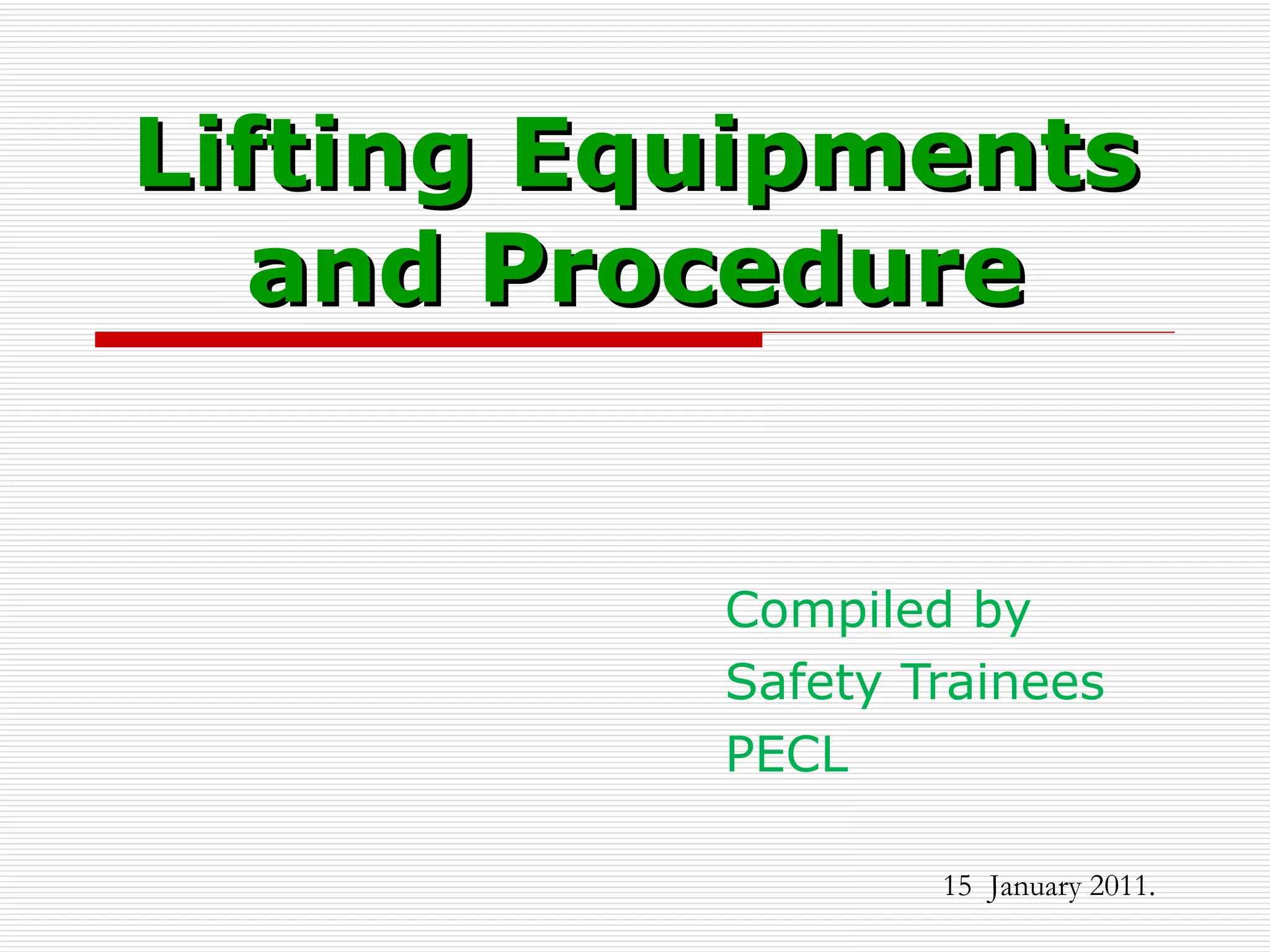
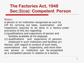
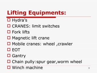
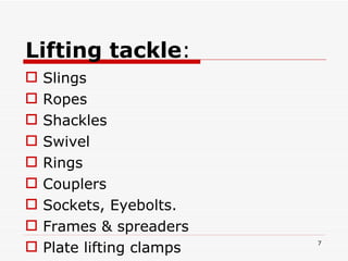
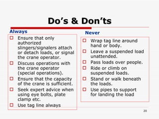
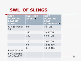
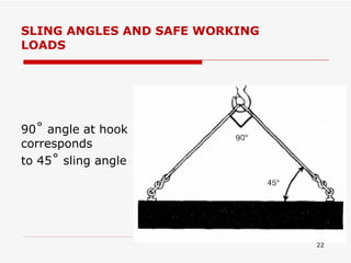
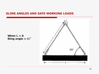
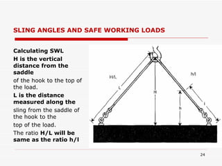
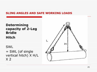
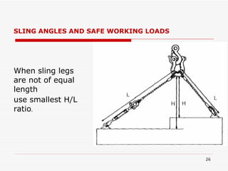
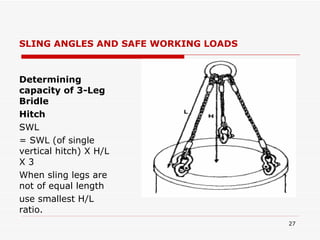
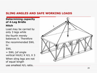
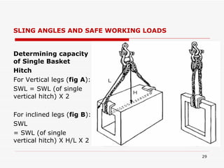
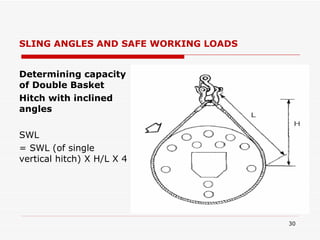
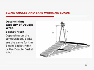
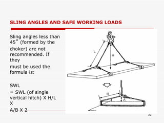
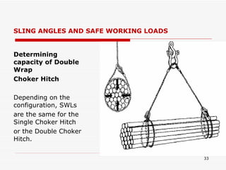
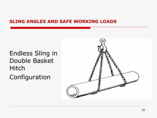
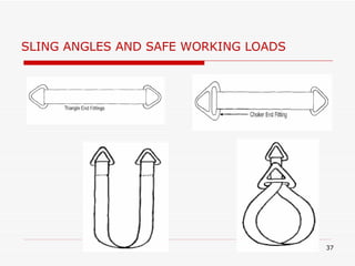
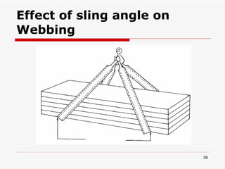
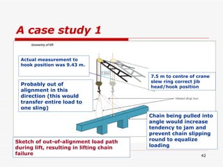
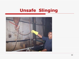
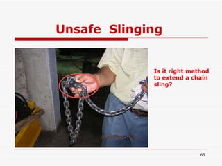
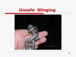
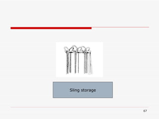


The document discusses lifting equipment and procedures as outlined in the Factories Act. It defines key terms like competent person, machinery, and lifting tackles. It provides guidelines for planning lifts, conducting the lift, landing loads, and dos and don'ts. It also examines sling angles and their effect on safe working loads. Case studies describe incidents where improper planning and techniques like misaligned loads led to injuries.


