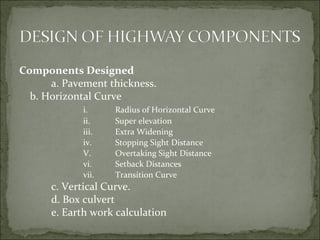
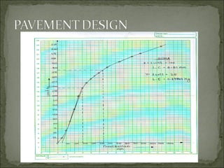
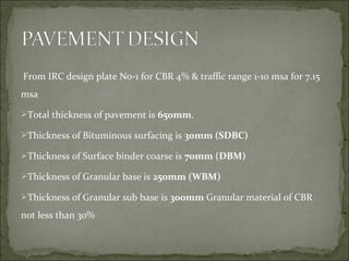
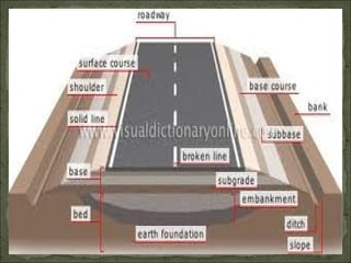
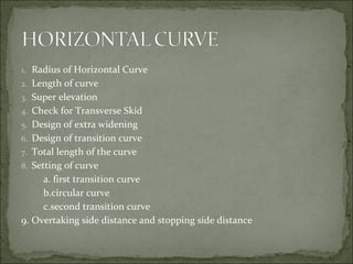
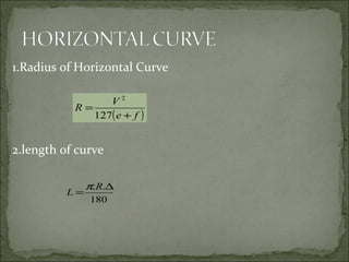
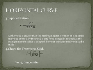
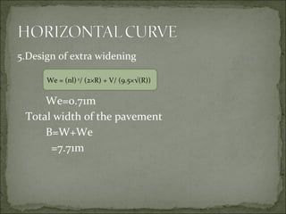
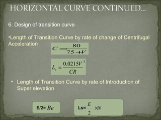
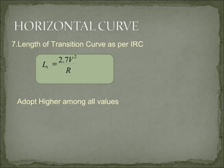
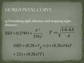
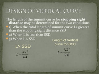
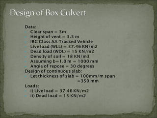
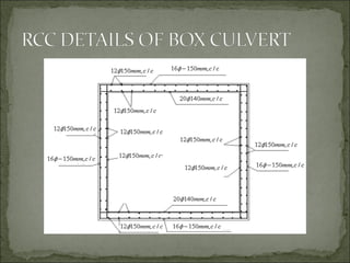
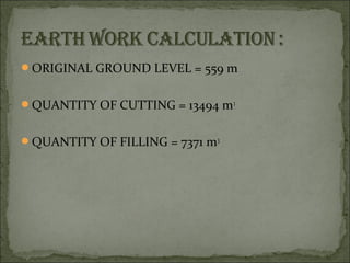
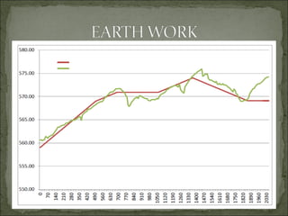
 1) Name of the project: Highway Project
 2) State/District/Taluka: Karnataka/Bijapur/Bijapur
 3) Location:
a) Distance of project site from the city: 7.00 KM
b) The nearest Railway station and its
distance from the project site : 10.00 KM
c) Distance of project site from college : 4.00 KM
 Longitudinal Section of Highway Line (Profile
Leveling along the center line of Proposed
Highway).
 Cross-Sections for the center line of Highway.
 Block Contouring for the Proposed Culvert.
 Dumpy level
 Prismatic Compass
 Chain, Tape, Arrows and Ranging Rods
Components Designed
a. Pavement thickness.
b. Horizontal Curve
i. Radius of Horizontal Curve
ii. Super elevation
iii. Extra Widening
iv. Stopping Sight Distance
V. Overtaking Sight Distance
vi. Setback Distances
vii. Transition Curve
c. Vertical Curve.
d. Box culvert
e. Earth work calculation
From IRC design plate No-1 for CBR 4% & traffic range 1-10 msa for 7.15
msa
Total thickness of pavement is 650mm.
Thickness of Bituminous surfacing is 30mm (SDBC)
Thickness of Surface binder coarse is 70mm (DBM)
Thickness of Granular base is 250mm (WBM)
Thickness of Granular sub base is 300mm Granular material of CBR
not less than 30%
1. Radius of Horizontal Curve
2. Length of curve
3. Super elevation
4. Check for Transverse Skid
5. Design of extra widening
6. Design of transition curve
7. Total length of the curve
8. Setting of curve
a. first transition curve
b.circular curve
c.second transition curve
9. Overtaking side distance and stopping side distance
1.Radius of Horizontal Curve
2.length of curve
( )fe
V
R
+
=
127
2
180
.. ∆
=
R
L
π
3.Super elevation.
As the value is greater than the maximum super elevation of 0.07 limits
the value of e to 0.07 the curve is safe for full speed of 80kmph as the
ruling minimum radius is adopted, however check for transverse skid is
made
4.Check for Transverse Skid.
f=0.15, hence safe
R
V
e
225
2
=
e
R
V
f −





=
127
2
5.Design of extra widening
We=0.71m
Total width of the pavement
B=W+We
=7.71m
We = (nl)2
/ (2×R) + V/ (9.5×√(R))
V
C
+
=
75
80
3
0215.0
CR
V
Ls =
6. Design of transition curve
•Length of Transition Curve by rate of change of Centrifugal
Acceleration
• Length of Transition Curve by rate of Introduction of
Super elevation
Ls=E/2= Be N
E
×
2
7.Length of Transition Curve as per IRC
Adopt Higher among all values
R
V
Ls
2
7.2=
9.Overtaking sight distance and stopping sight
distance
f
V
VtSSD
254
278.0
2
+=
A
S
T
4.14
=
)28.0()2
28.0()28.0(
xVTS
xVbxTtbVOSD
++
+××=
The length of the summit curve for stopping sight
distance may be determined for the two conditions:
1) When the total length of summit curve Ls greater
than the stopping sight distance SSD
2) When L is less than SSD.
3) When L > SSD
4.4
2
NS
L =
L> SSD
Length of Vertical
curve for OSD
6.9
2
NS
L =
ORIGINAL GROUND LEVEL = 559 m
QUANTITY OF CUTTING = 13494 m33
QUANTITY OF FILLING = 7371 m3
Highway Project
Highway Project

Highway Project

  • 2.
     1) Nameof the project: Highway Project  2) State/District/Taluka: Karnataka/Bijapur/Bijapur  3) Location: a) Distance of project site from the city: 7.00 KM b) The nearest Railway station and its distance from the project site : 10.00 KM c) Distance of project site from college : 4.00 KM
  • 5.
     Longitudinal Sectionof Highway Line (Profile Leveling along the center line of Proposed Highway).  Cross-Sections for the center line of Highway.  Block Contouring for the Proposed Culvert.
  • 6.
     Dumpy level Prismatic Compass  Chain, Tape, Arrows and Ranging Rods
  • 7.
    Components Designed a. Pavementthickness. b. Horizontal Curve i. Radius of Horizontal Curve ii. Super elevation iii. Extra Widening iv. Stopping Sight Distance V. Overtaking Sight Distance vi. Setback Distances vii. Transition Curve c. Vertical Curve. d. Box culvert e. Earth work calculation
  • 9.
    From IRC designplate No-1 for CBR 4% & traffic range 1-10 msa for 7.15 msa Total thickness of pavement is 650mm. Thickness of Bituminous surfacing is 30mm (SDBC) Thickness of Surface binder coarse is 70mm (DBM) Thickness of Granular base is 250mm (WBM) Thickness of Granular sub base is 300mm Granular material of CBR not less than 30%
  • 12.
    1. Radius ofHorizontal Curve 2. Length of curve 3. Super elevation 4. Check for Transverse Skid 5. Design of extra widening 6. Design of transition curve 7. Total length of the curve 8. Setting of curve a. first transition curve b.circular curve c.second transition curve 9. Overtaking side distance and stopping side distance
  • 13.
    1.Radius of HorizontalCurve 2.length of curve ( )fe V R + = 127 2 180 .. ∆ = R L π
  • 14.
    3.Super elevation. As thevalue is greater than the maximum super elevation of 0.07 limits the value of e to 0.07 the curve is safe for full speed of 80kmph as the ruling minimum radius is adopted, however check for transverse skid is made 4.Check for Transverse Skid. f=0.15, hence safe R V e 225 2 = e R V f −      = 127 2
  • 15.
    5.Design of extrawidening We=0.71m Total width of the pavement B=W+We =7.71m We = (nl)2 / (2×R) + V/ (9.5×√(R))
  • 16.
    V C + = 75 80 3 0215.0 CR V Ls = 6. Designof transition curve •Length of Transition Curve by rate of change of Centrifugal Acceleration • Length of Transition Curve by rate of Introduction of Super elevation Ls=E/2= Be N E × 2
  • 17.
    7.Length of TransitionCurve as per IRC Adopt Higher among all values R V Ls 2 7.2=
  • 18.
    9.Overtaking sight distanceand stopping sight distance f V VtSSD 254 278.0 2 += A S T 4.14 = )28.0()2 28.0()28.0( xVTS xVbxTtbVOSD ++ +××=
  • 19.
    The length ofthe summit curve for stopping sight distance may be determined for the two conditions: 1) When the total length of summit curve Ls greater than the stopping sight distance SSD 2) When L is less than SSD. 3) When L > SSD 4.4 2 NS L = L> SSD Length of Vertical curve for OSD 6.9 2 NS L =
  • 23.
    ORIGINAL GROUND LEVEL= 559 m QUANTITY OF CUTTING = 13494 m33 QUANTITY OF FILLING = 7371 m3