High Level Software Applications for Machine Control was presented by Shannon Krause and covered:
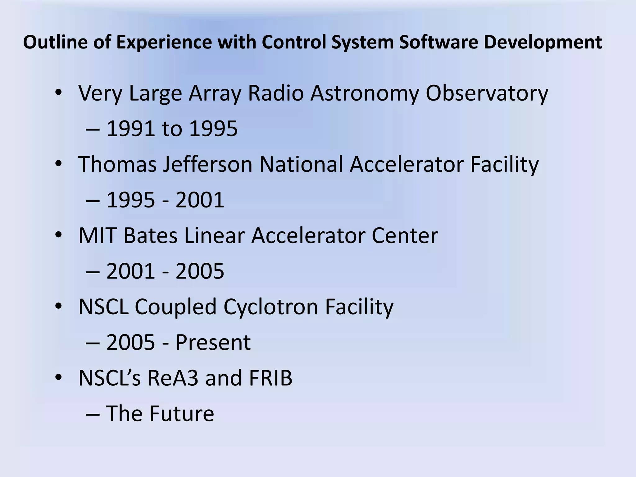
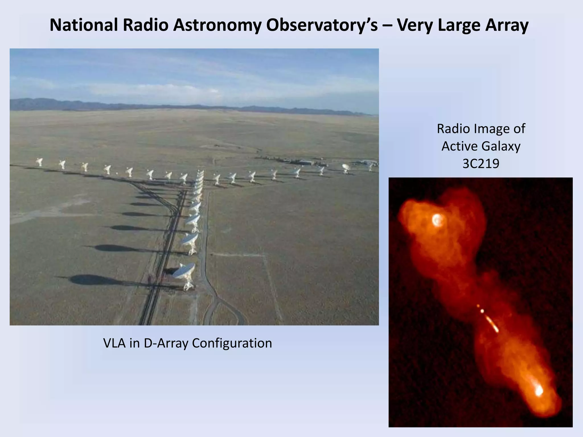
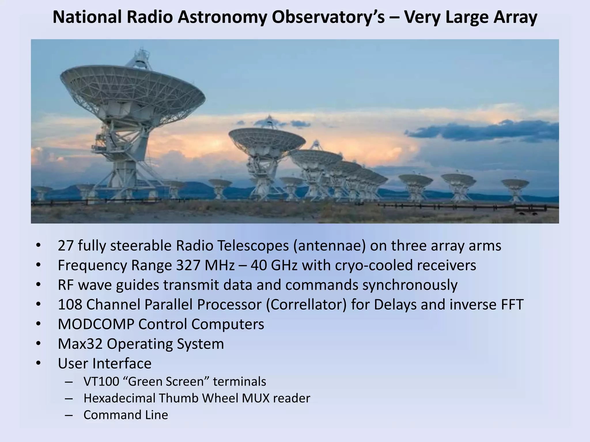
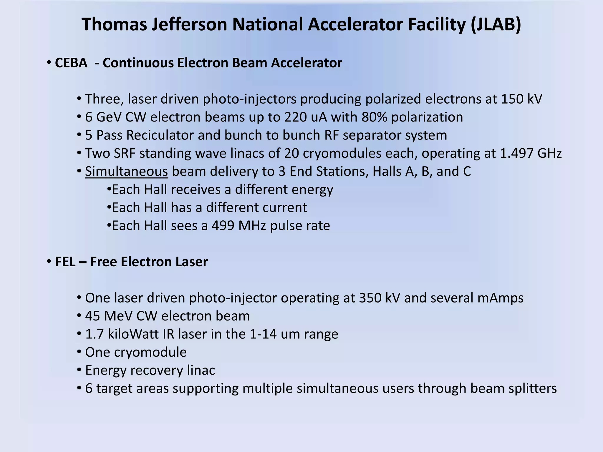
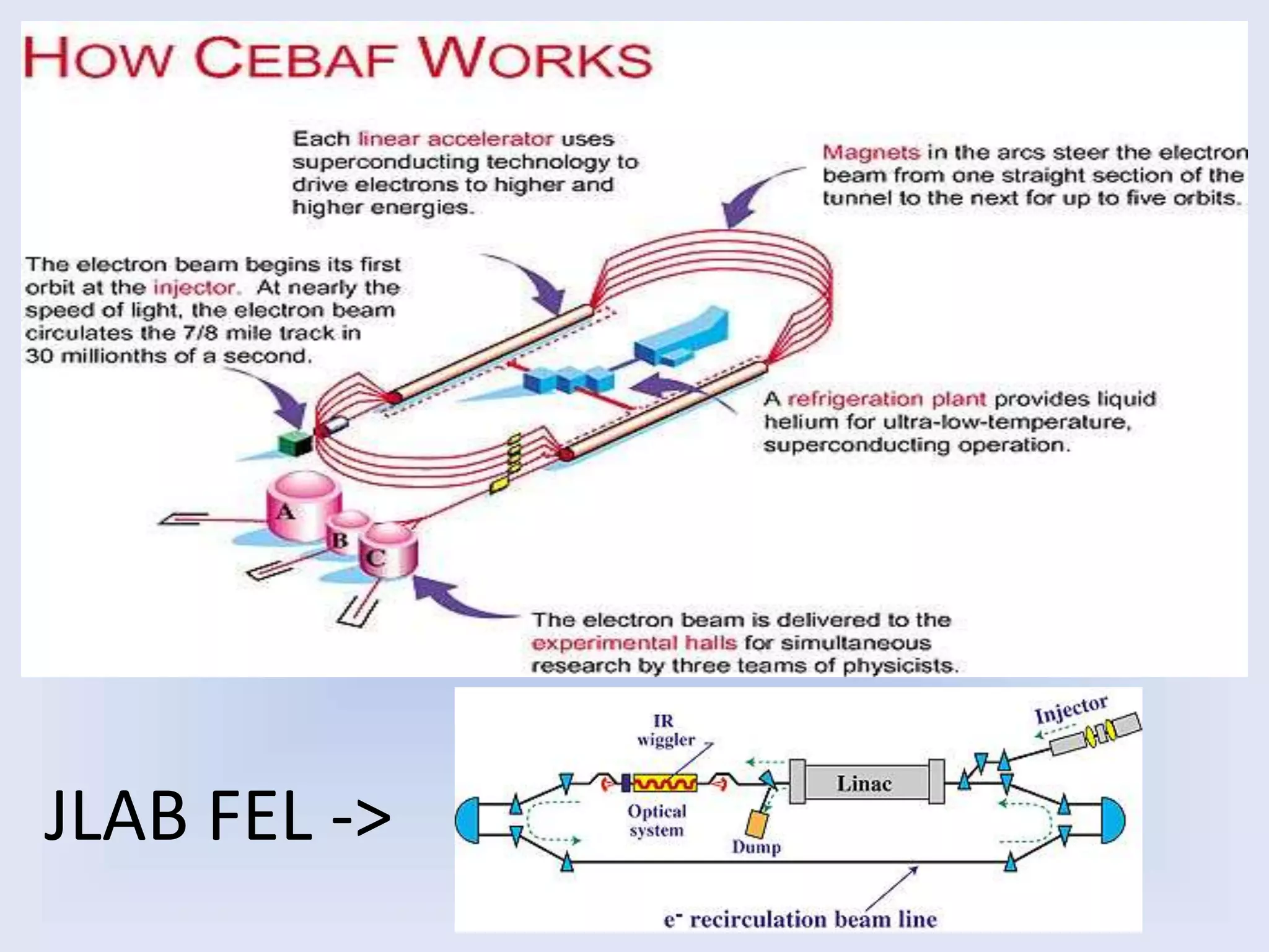
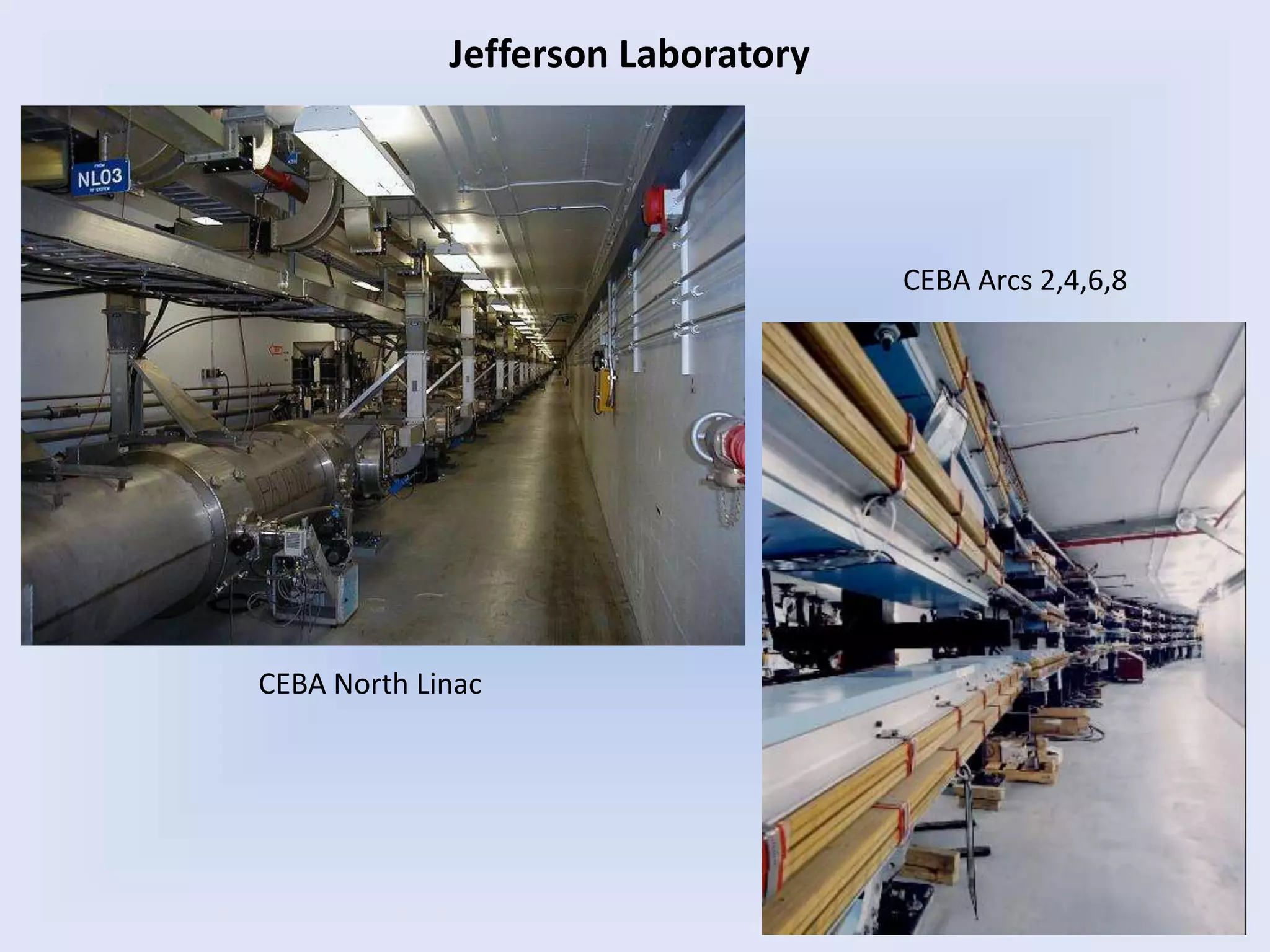
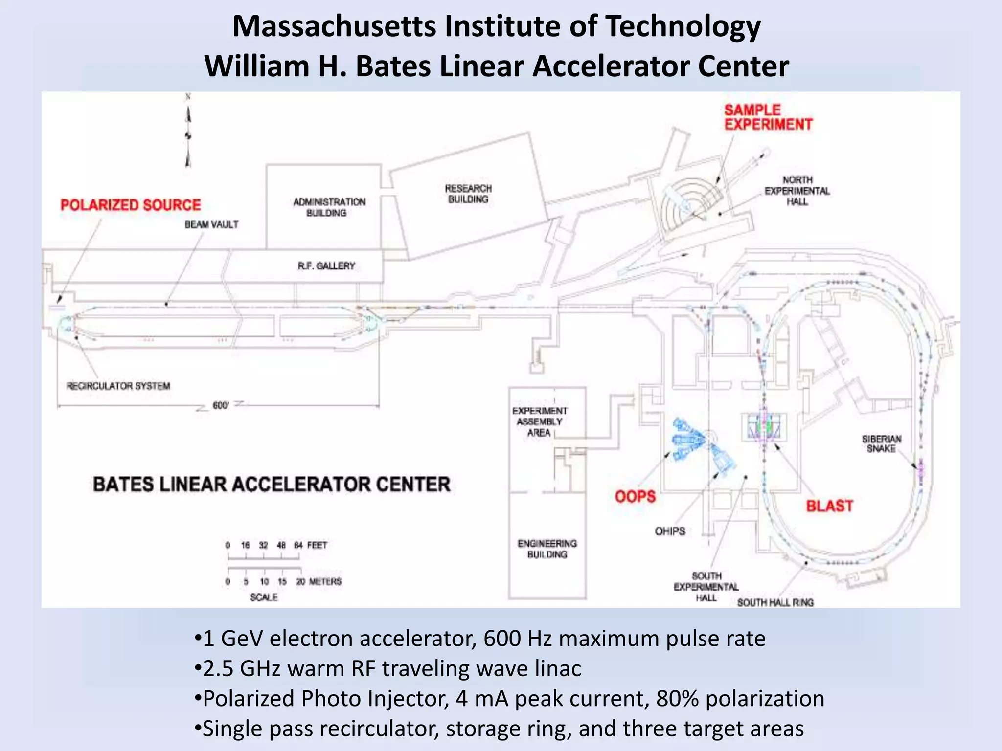
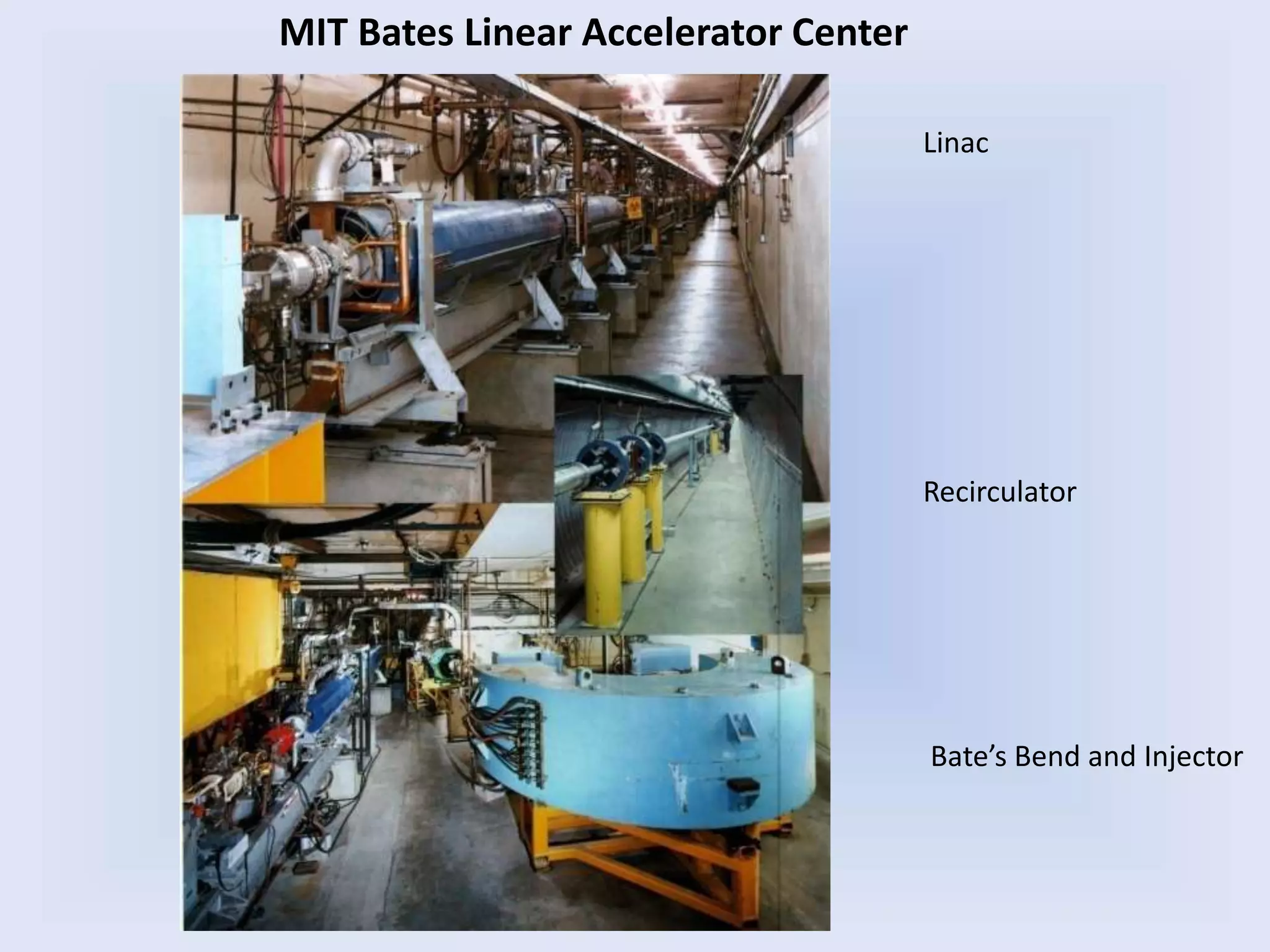
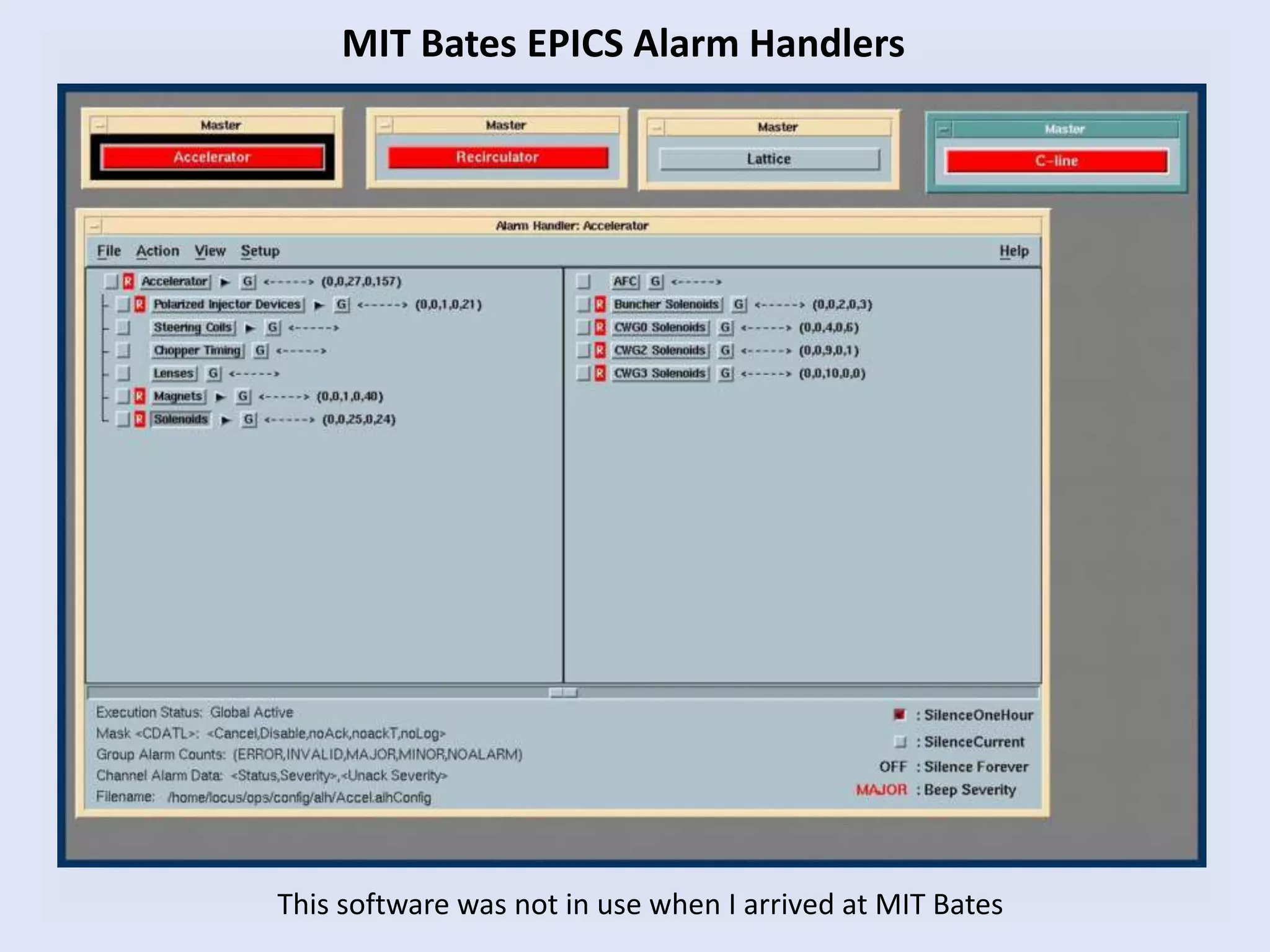
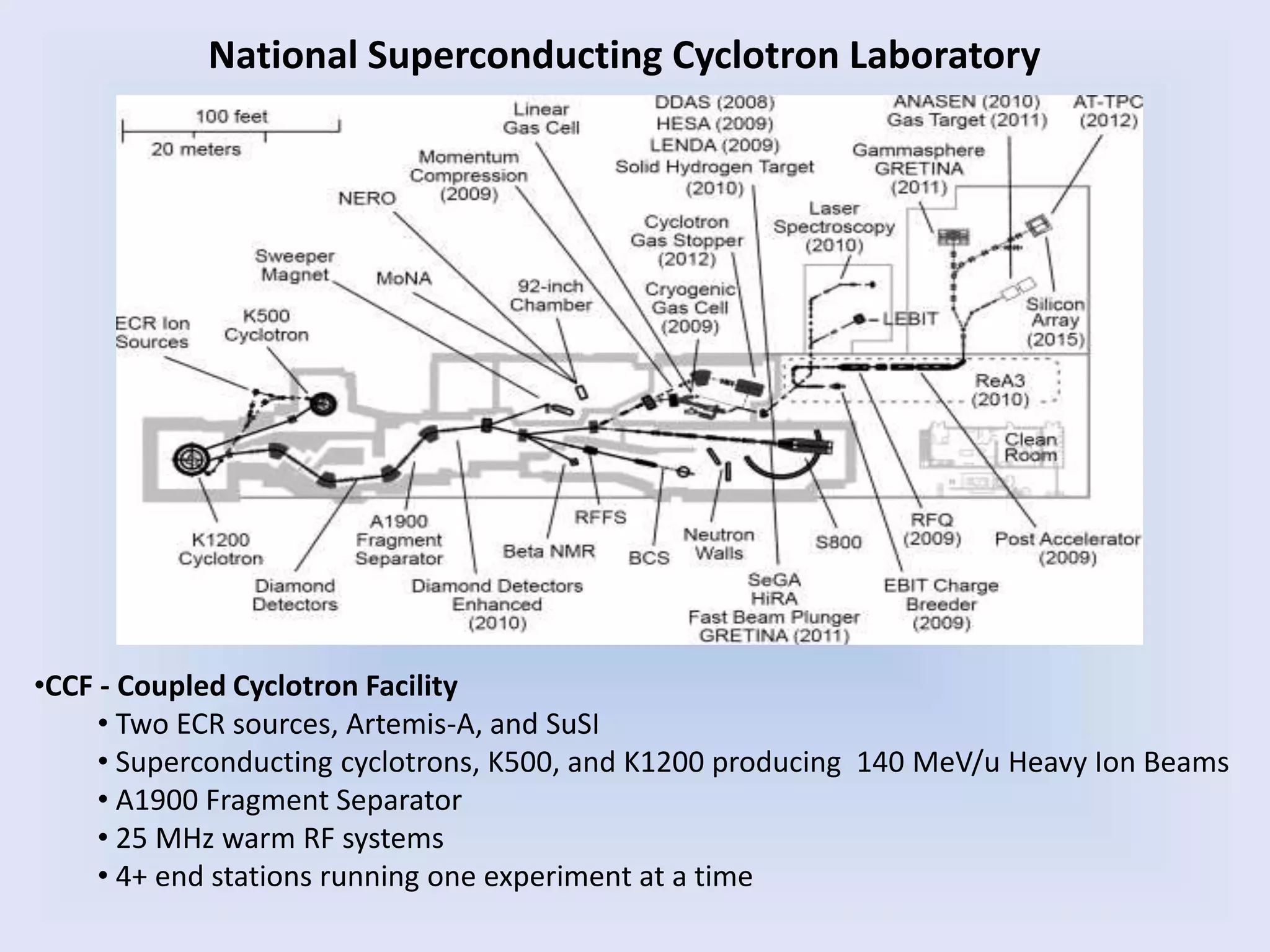
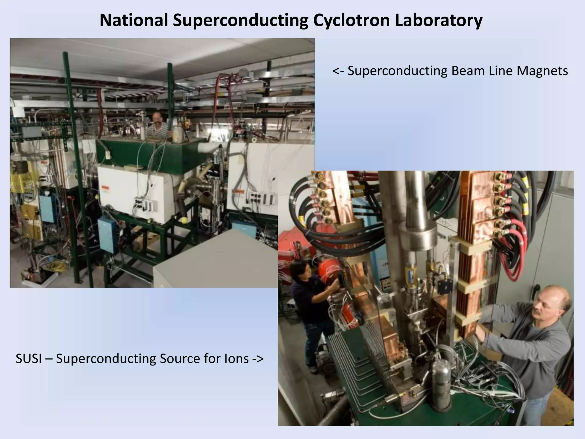
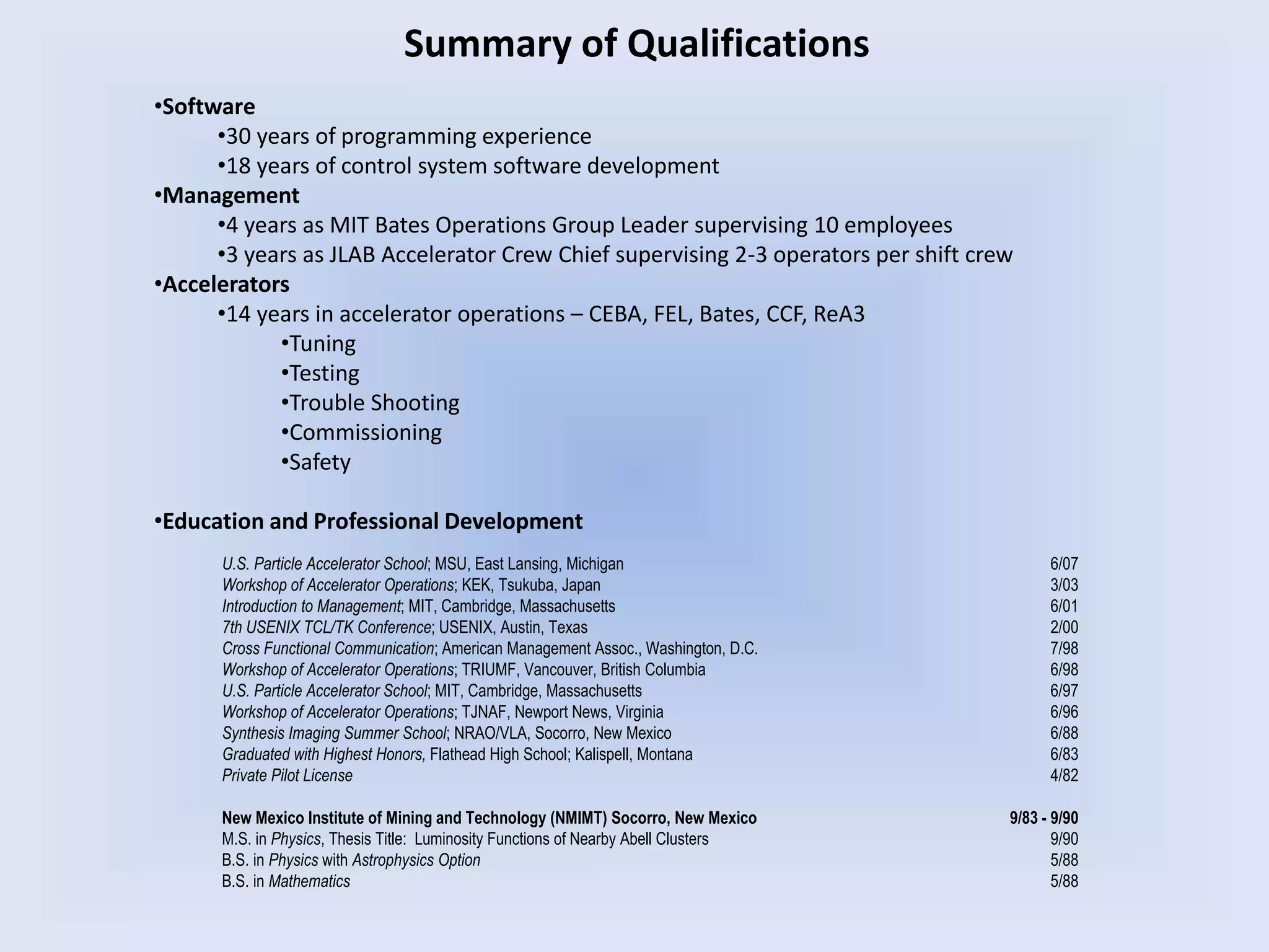
- Her experience developing control system software at several facilities including the Very Large Array Radio Astronomy Observatory, Thomas Jefferson National Accelerator Facility, and MIT Bates Linear Accelerator Center.
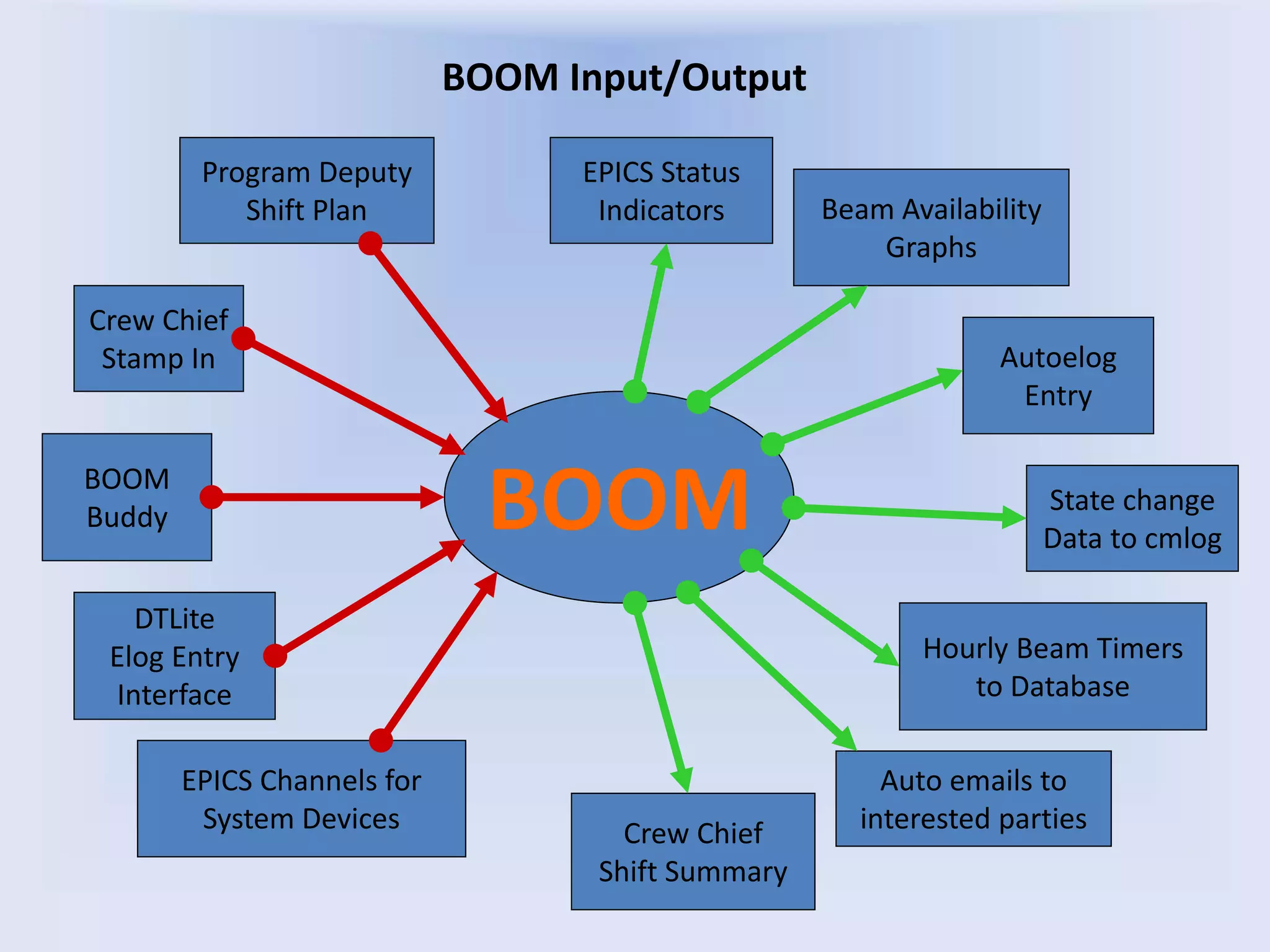
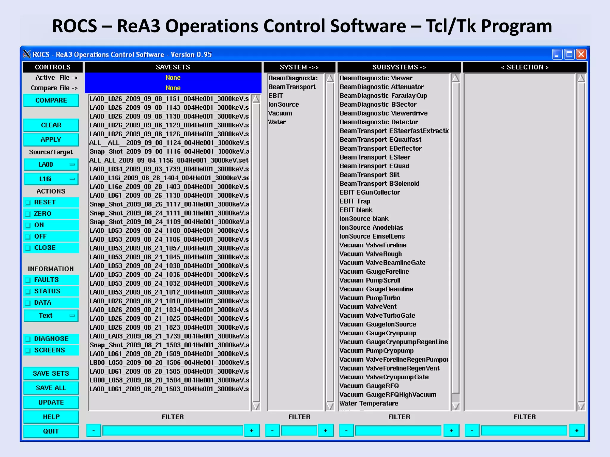
- Concepts in high level software applications including how they are the interface between humans and machines and should be designed around user needs.
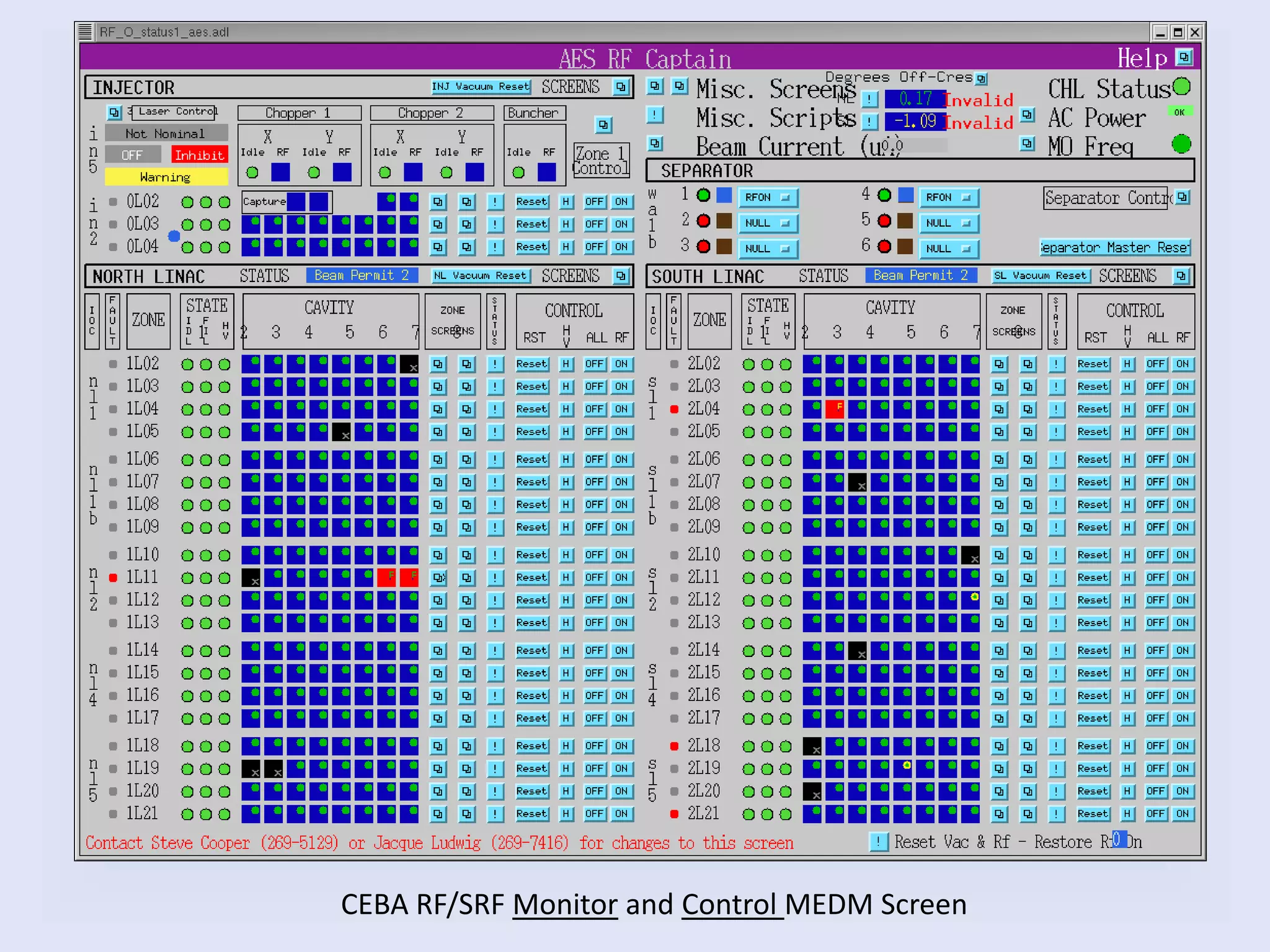
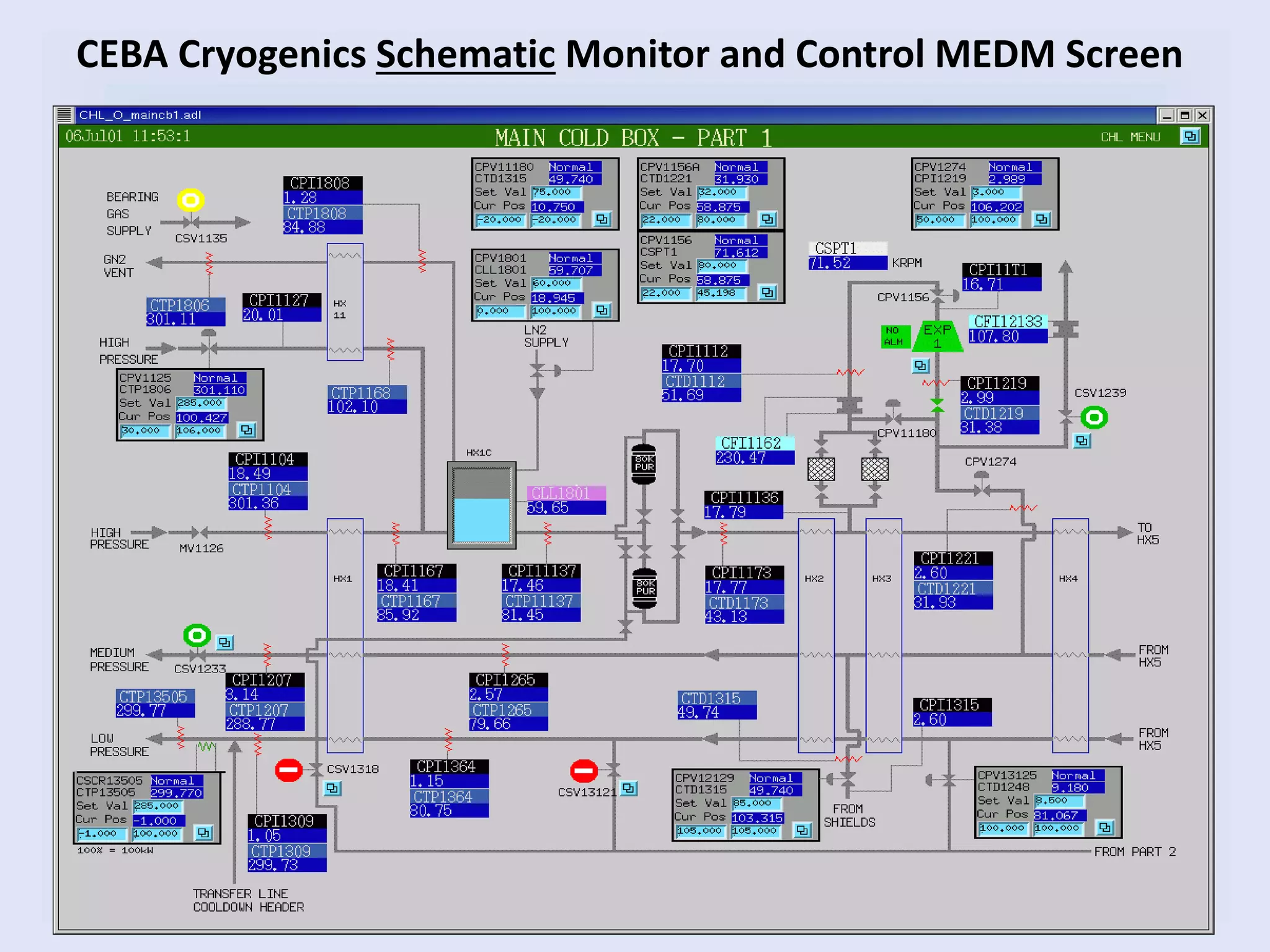
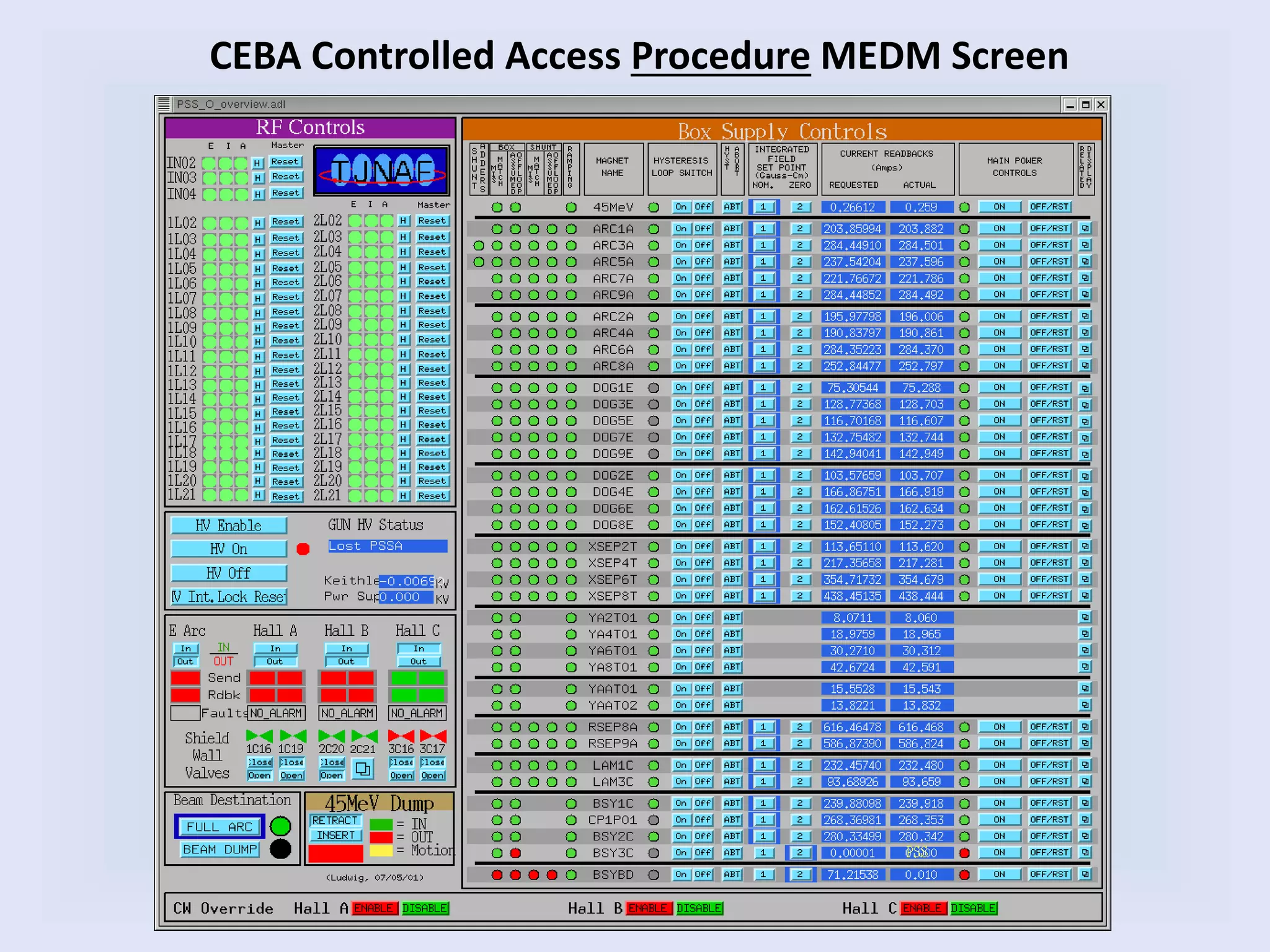
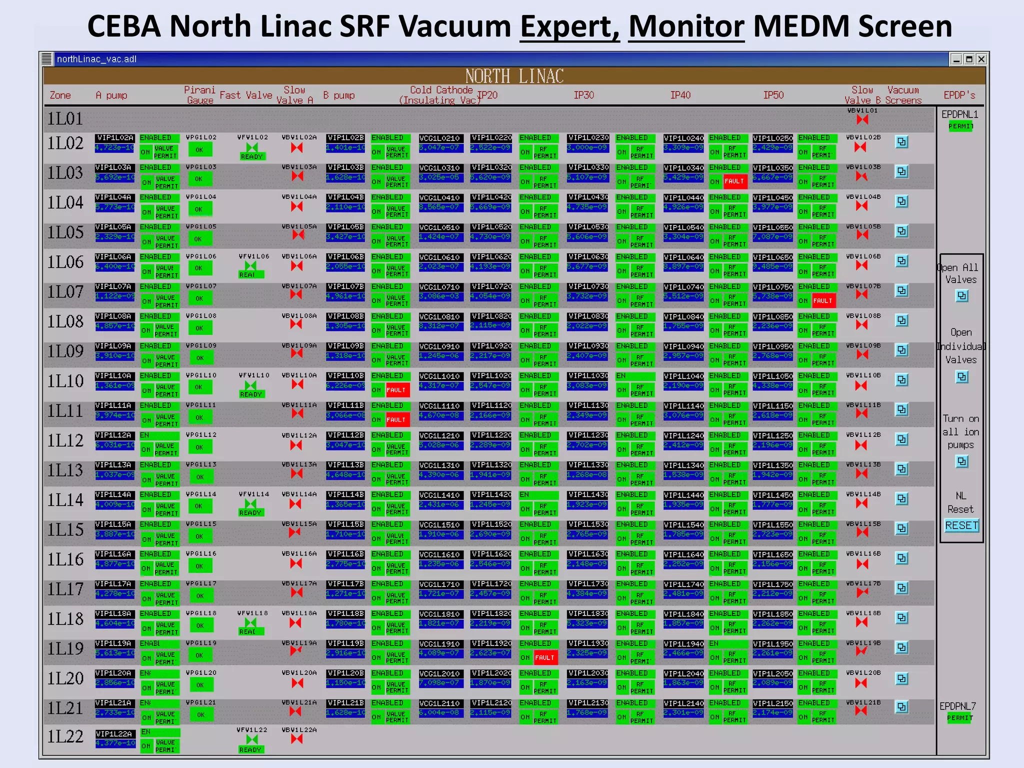
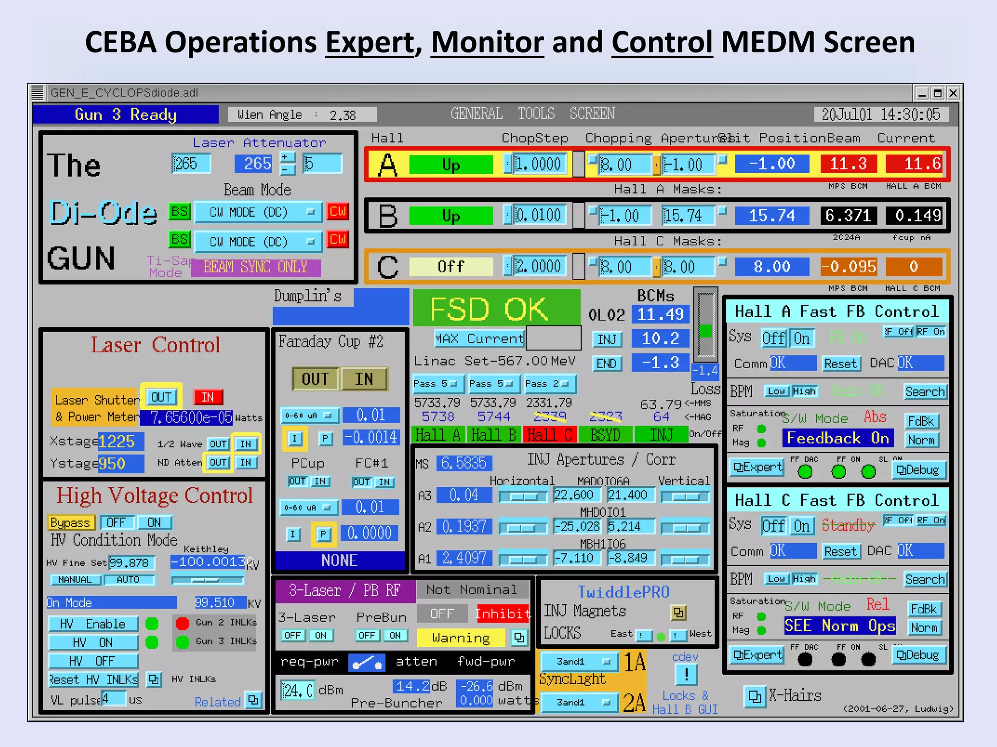
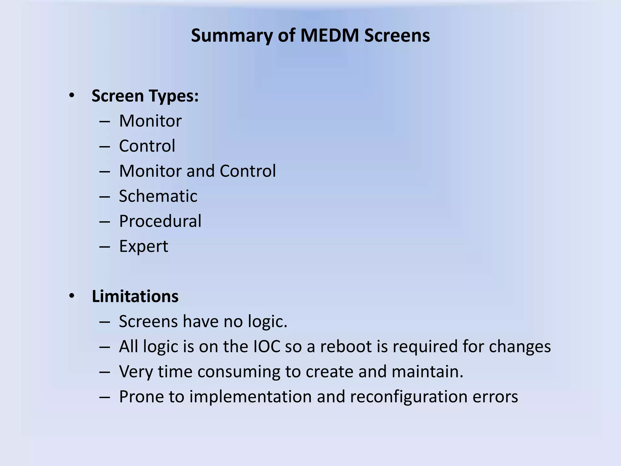
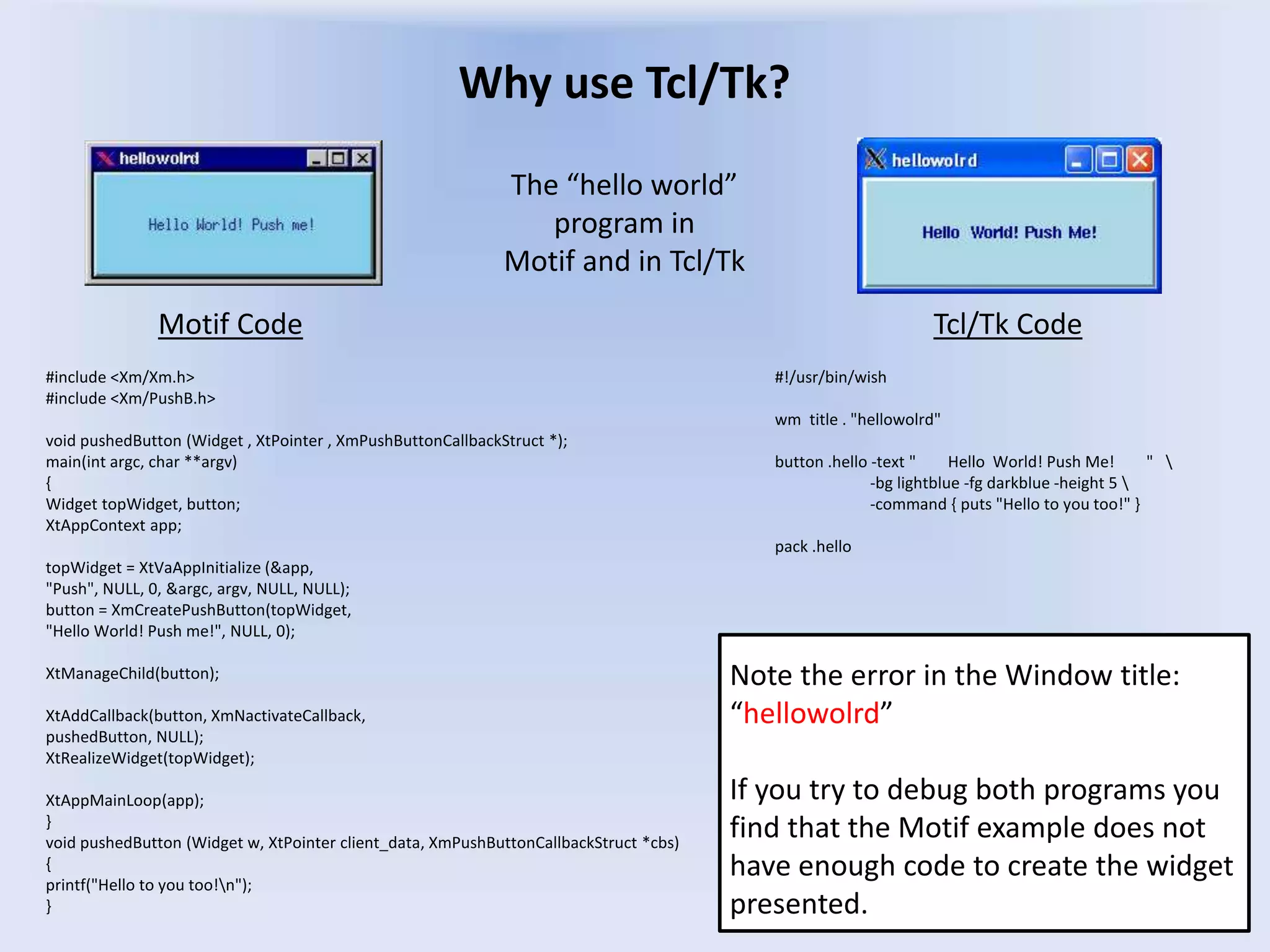
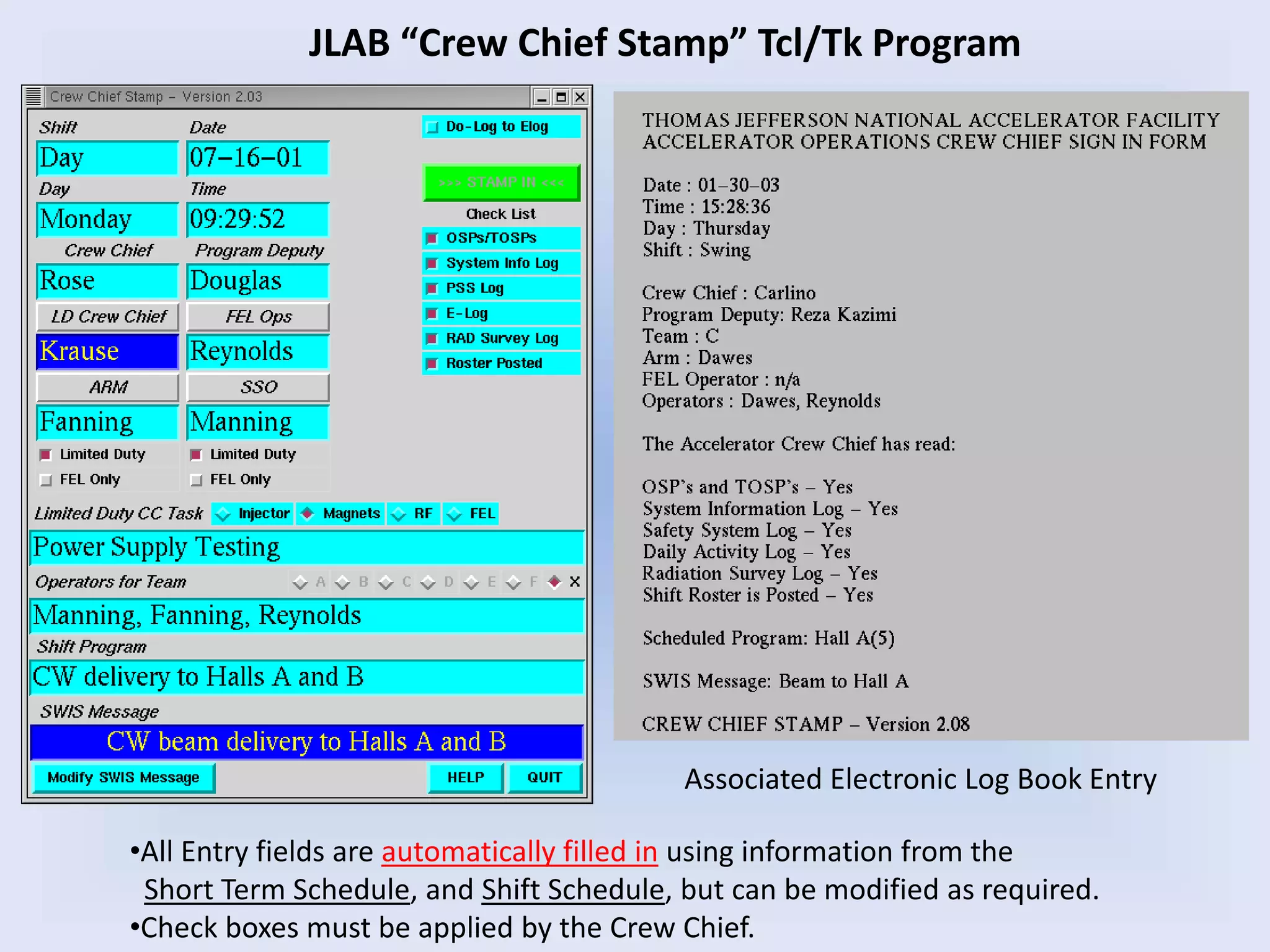
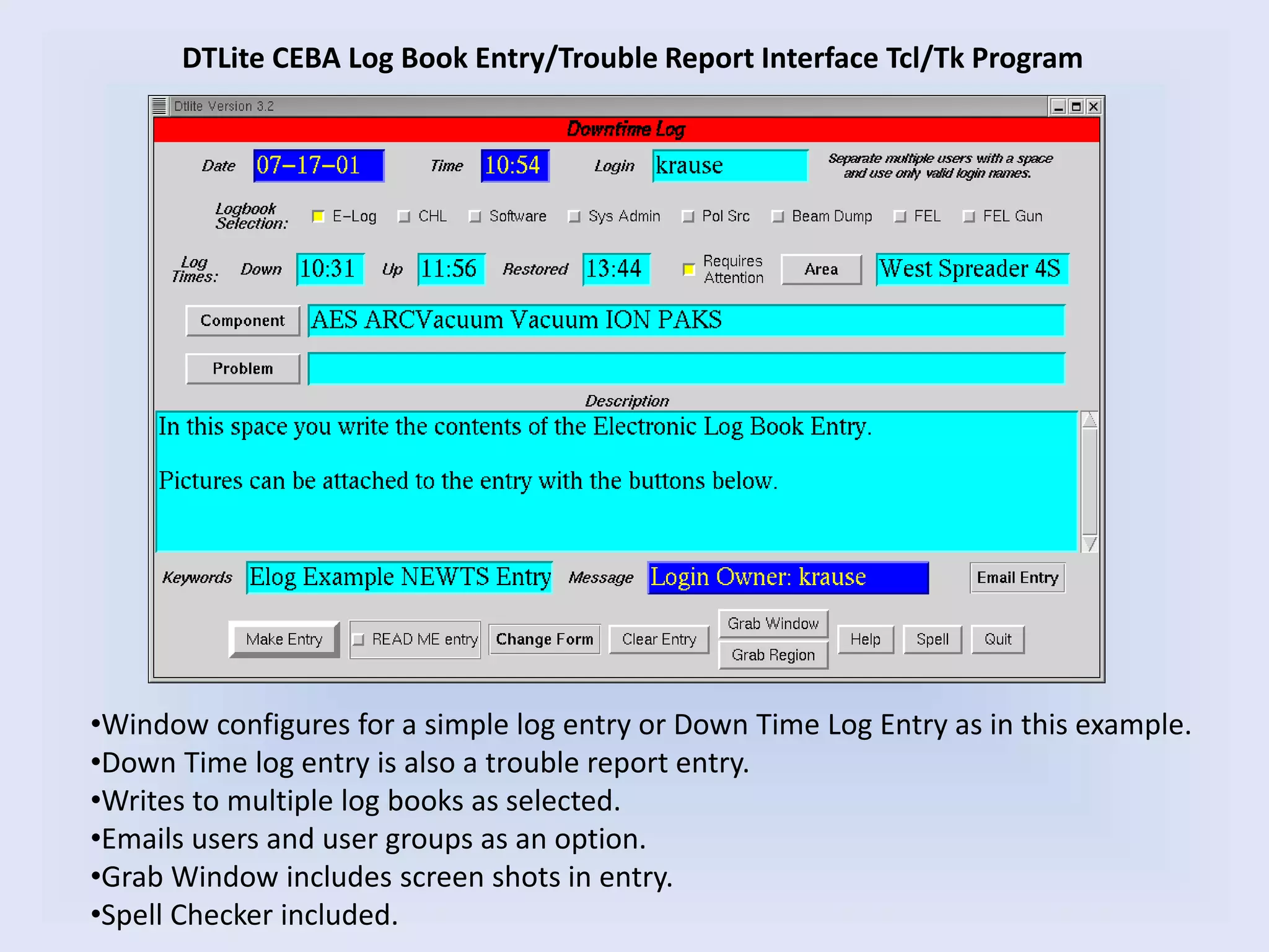
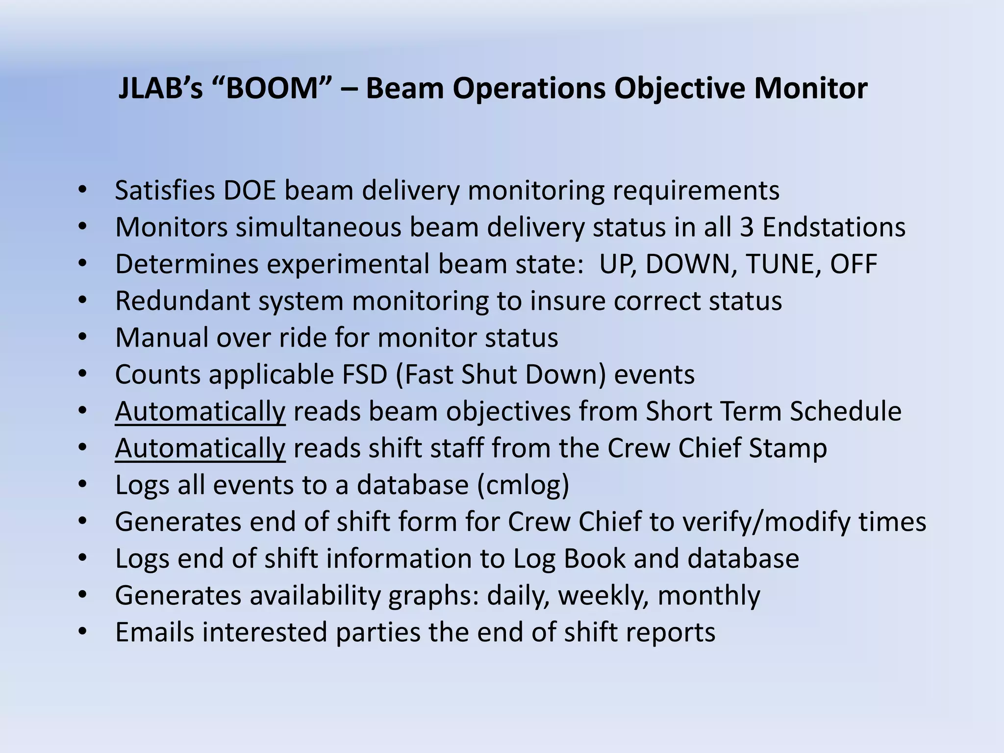
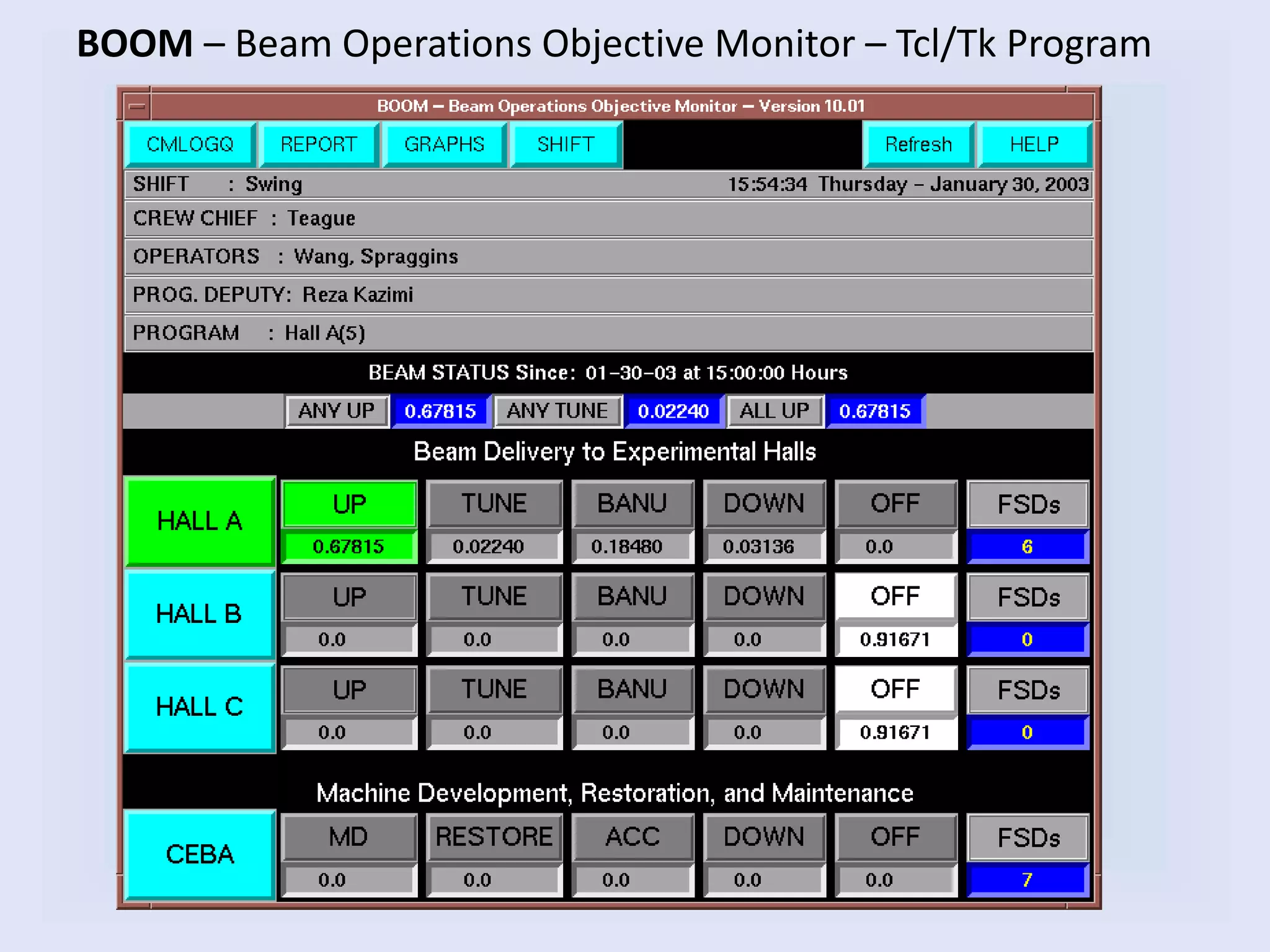
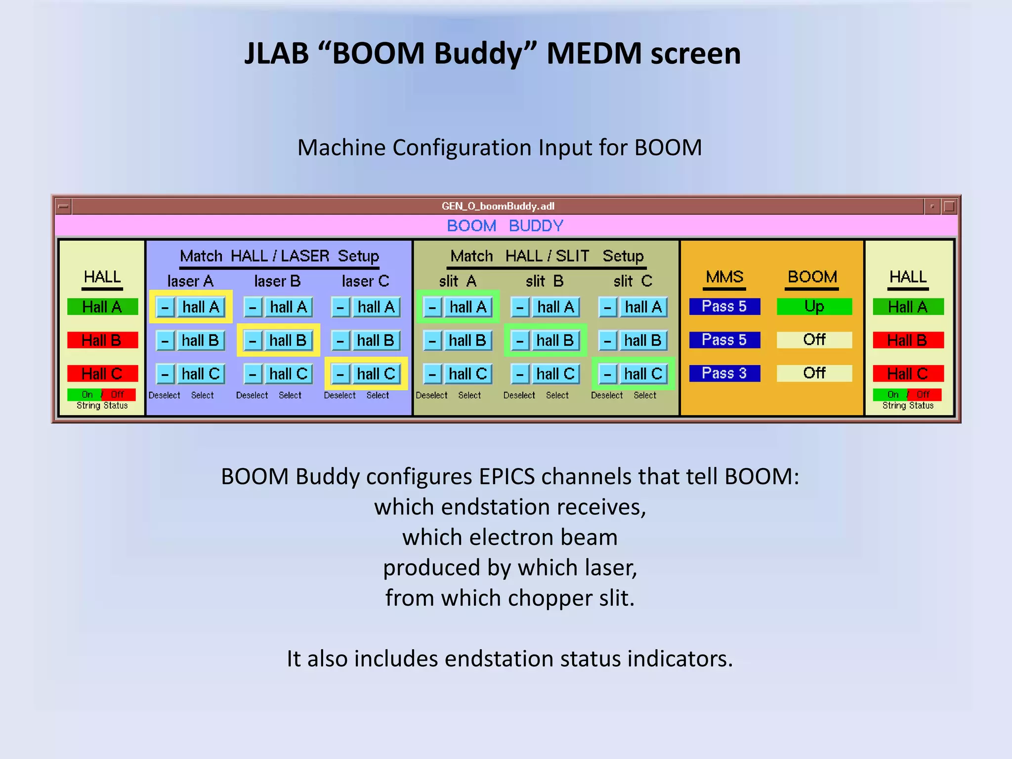
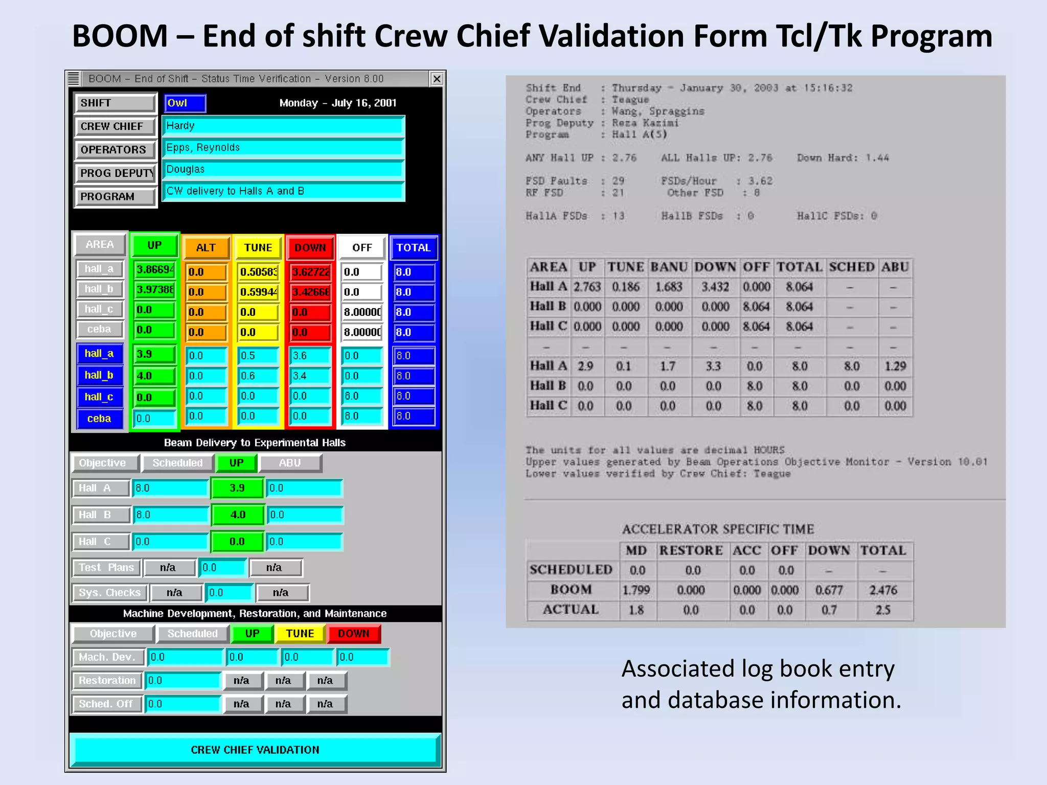
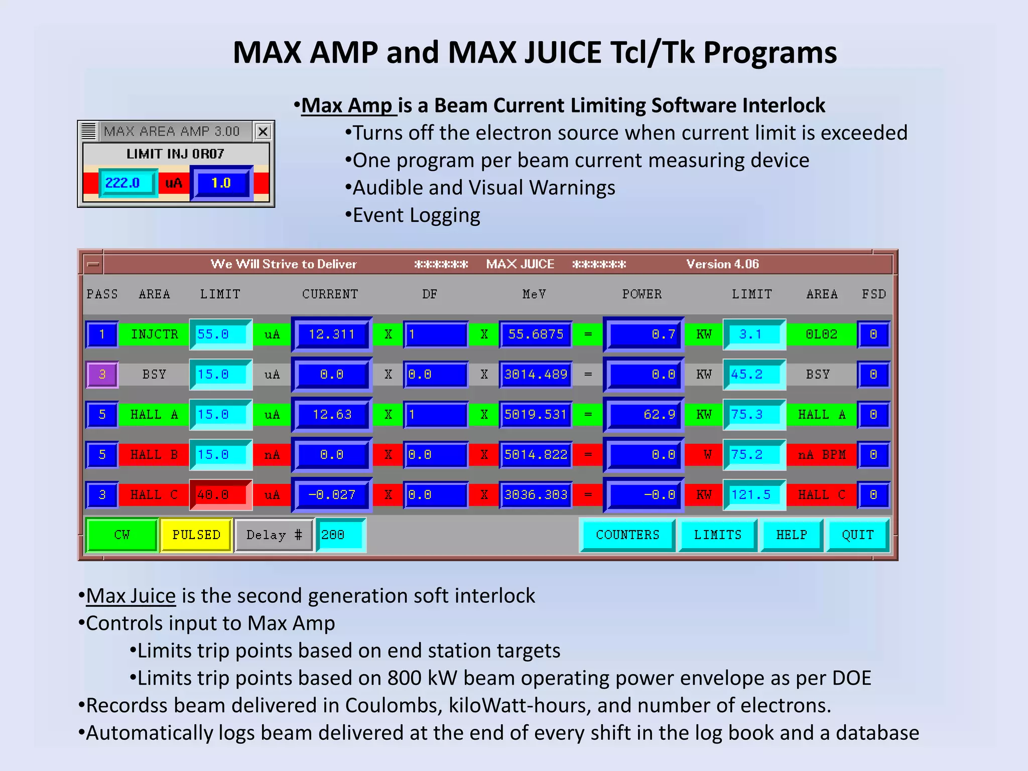
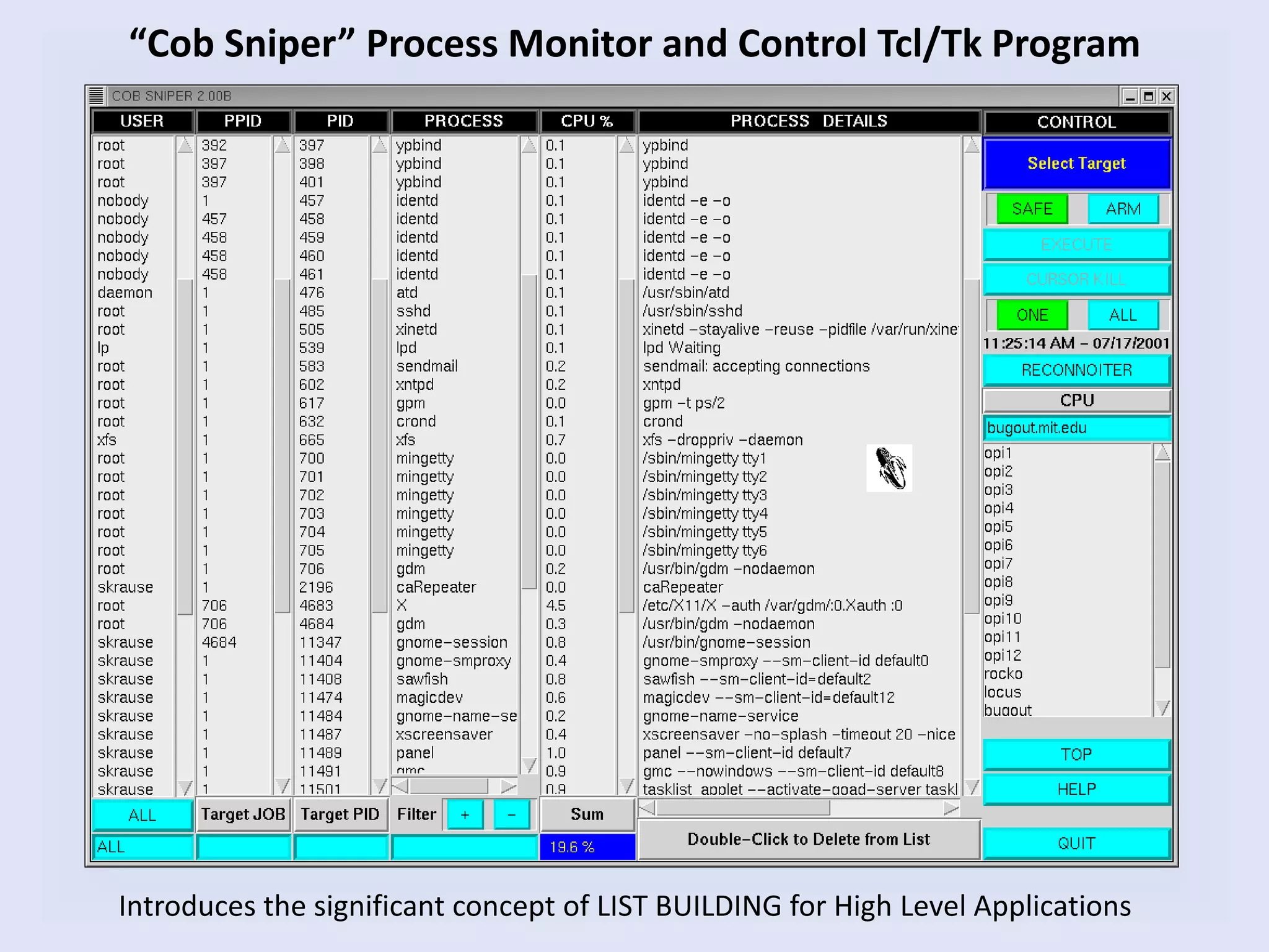
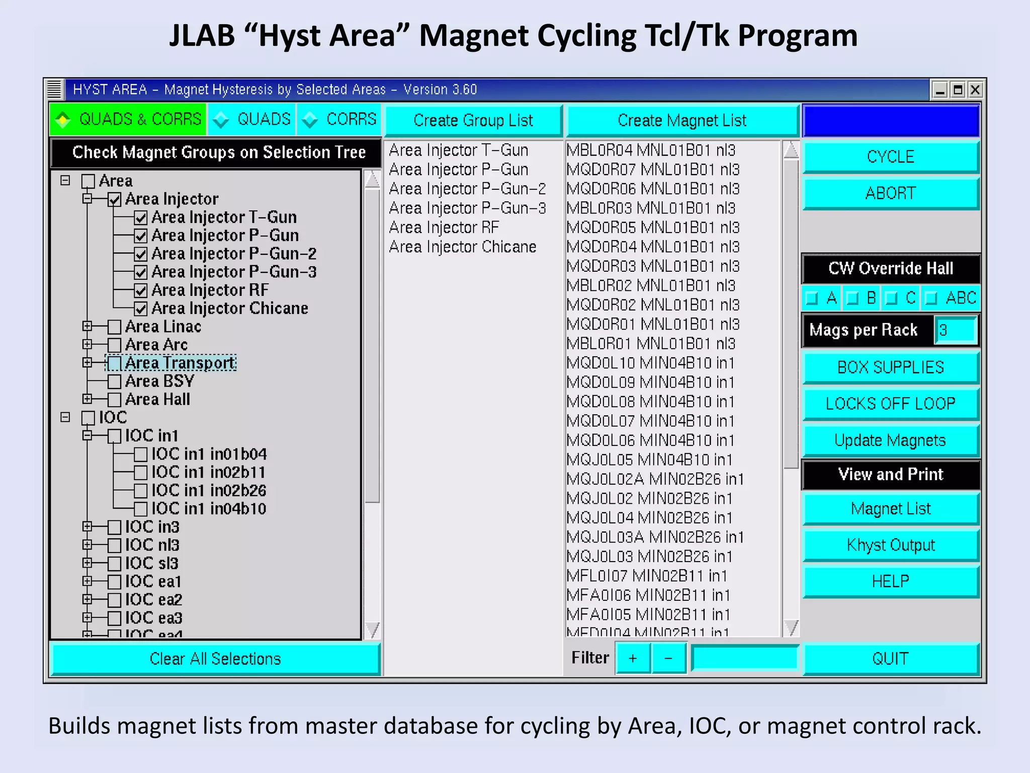
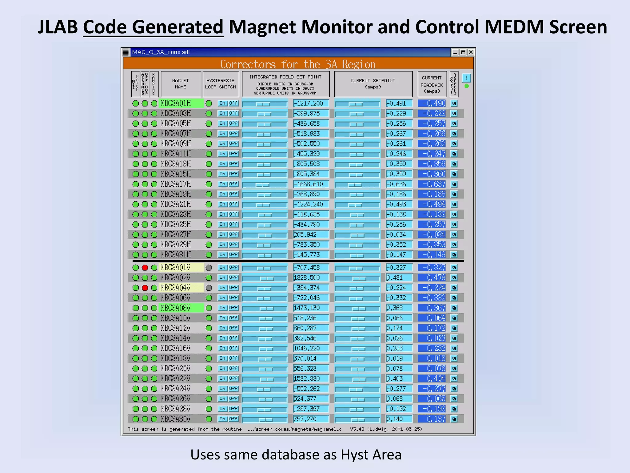
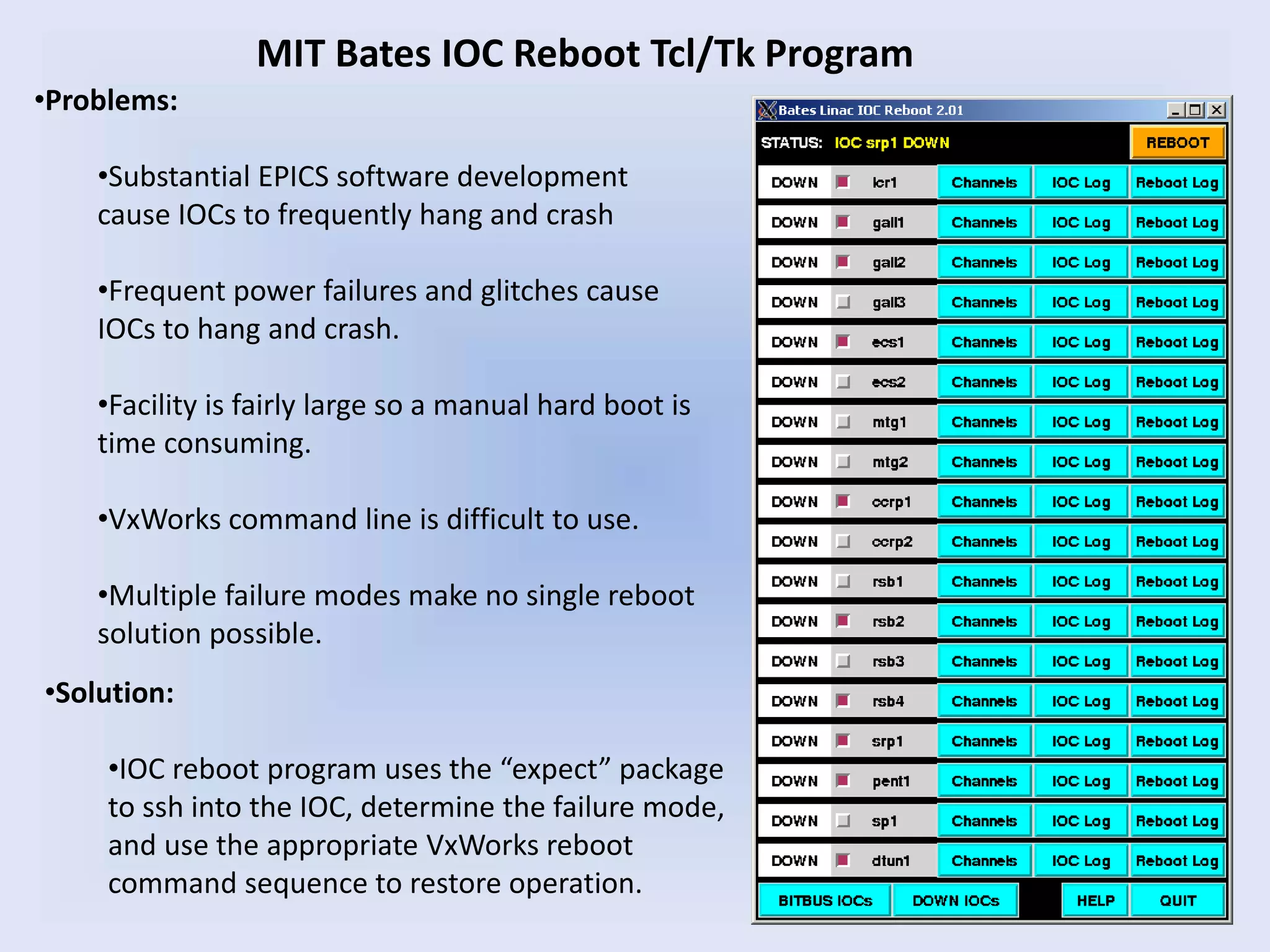
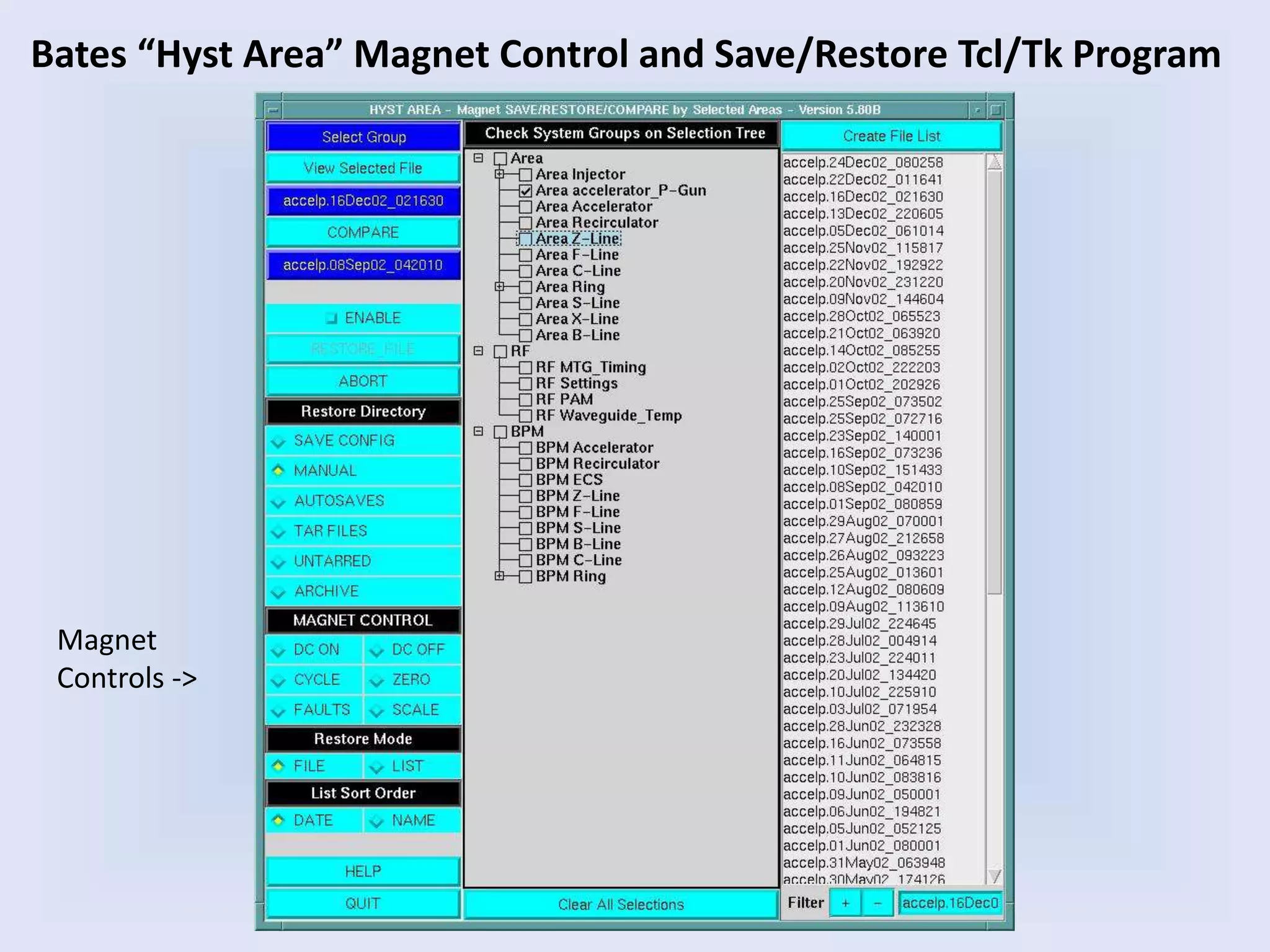
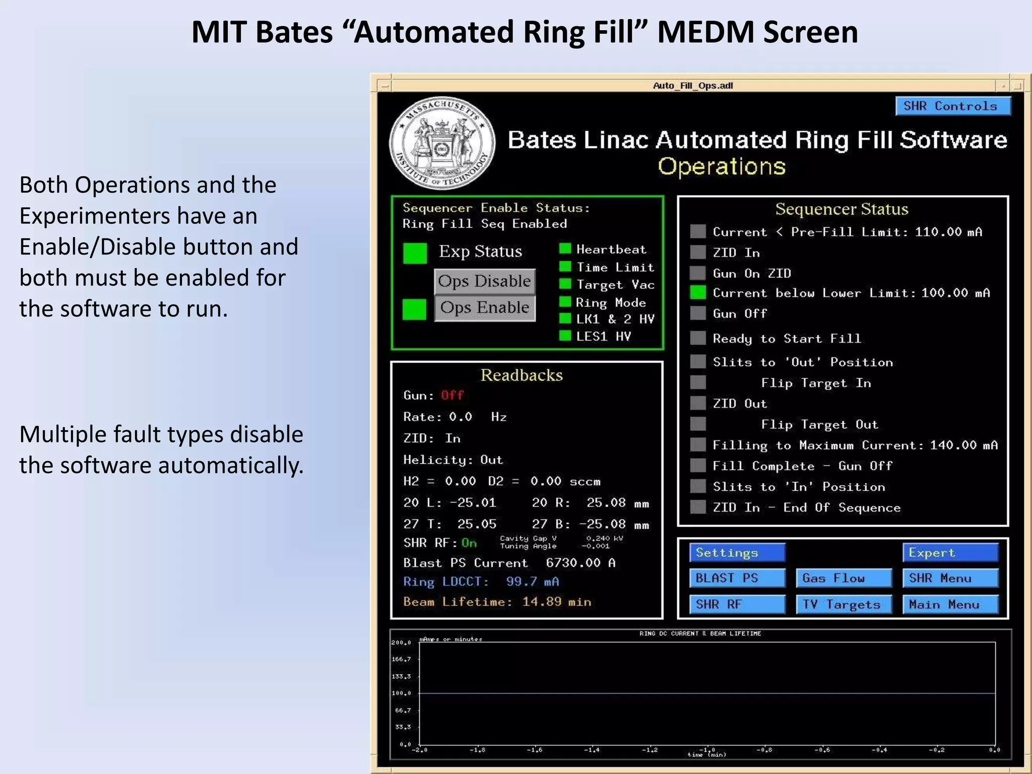
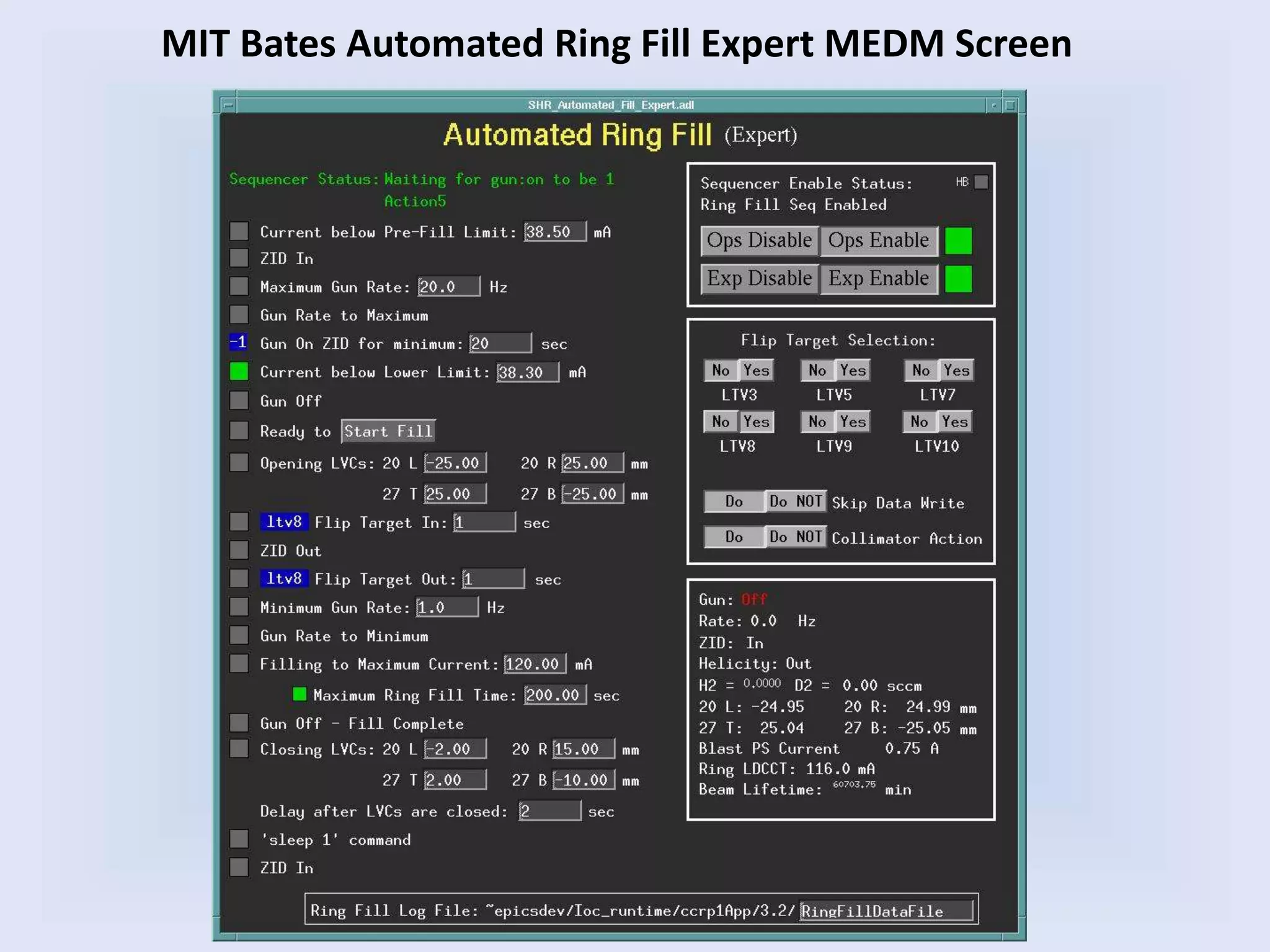
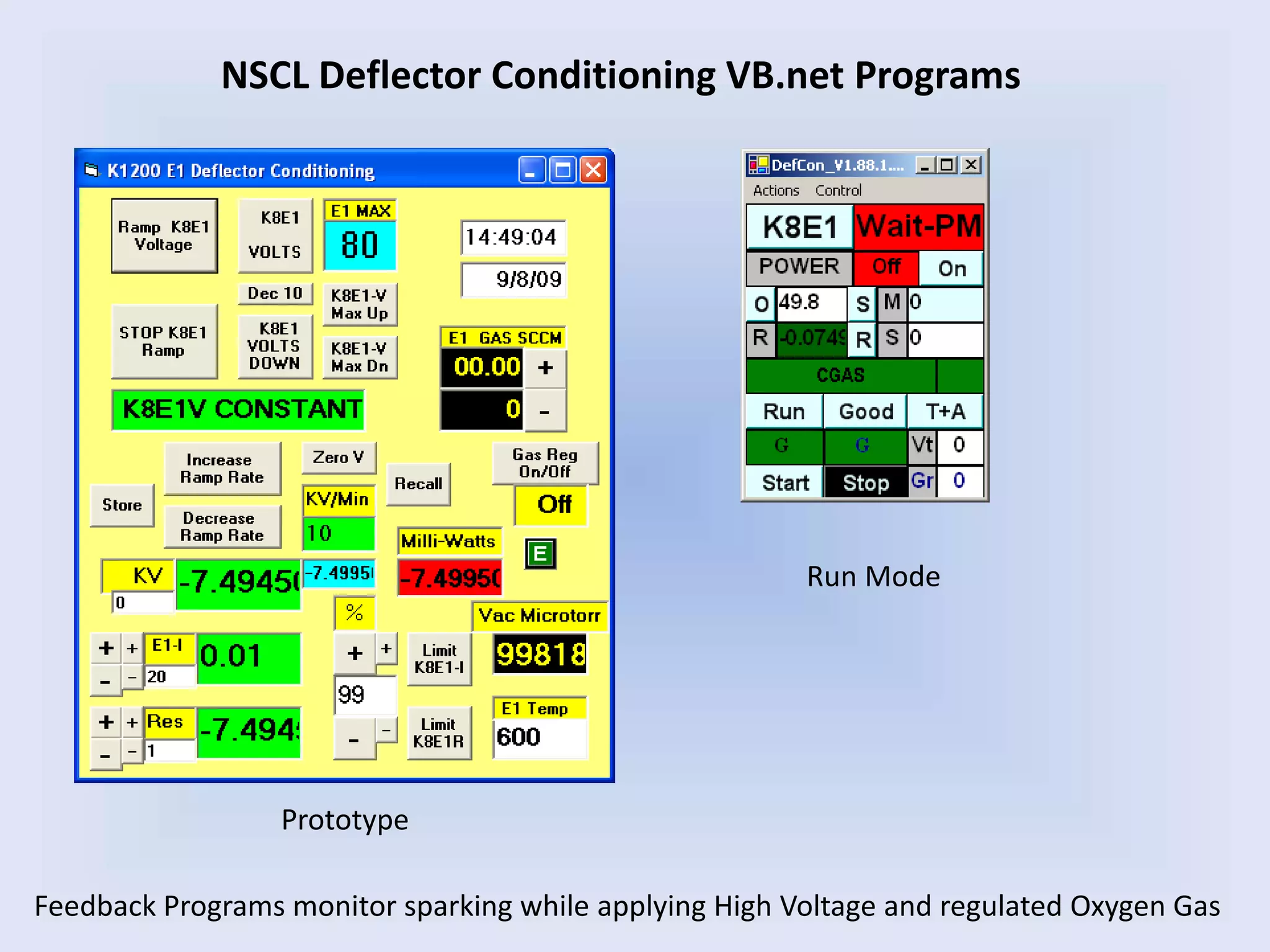
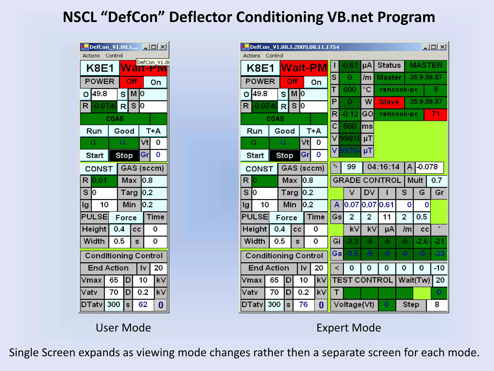
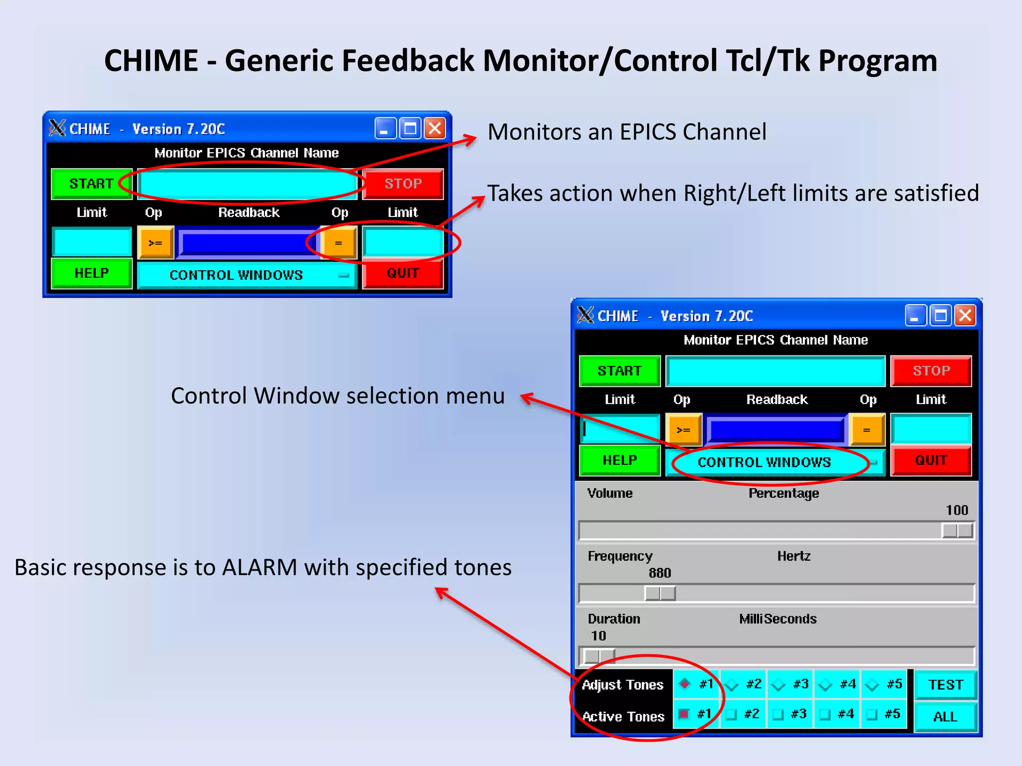
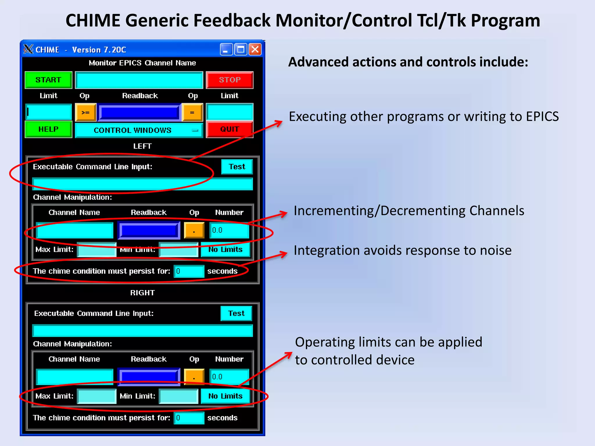
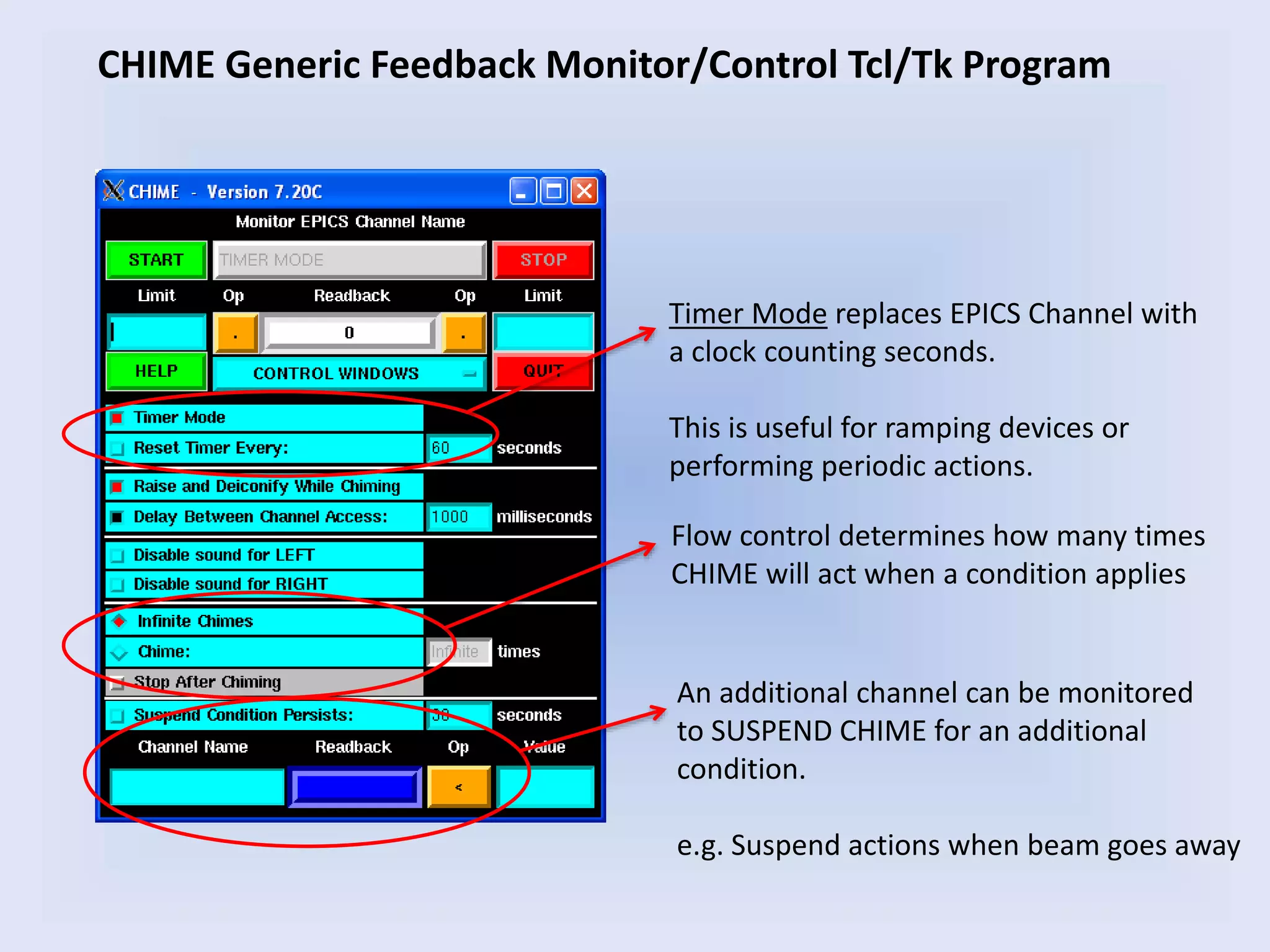
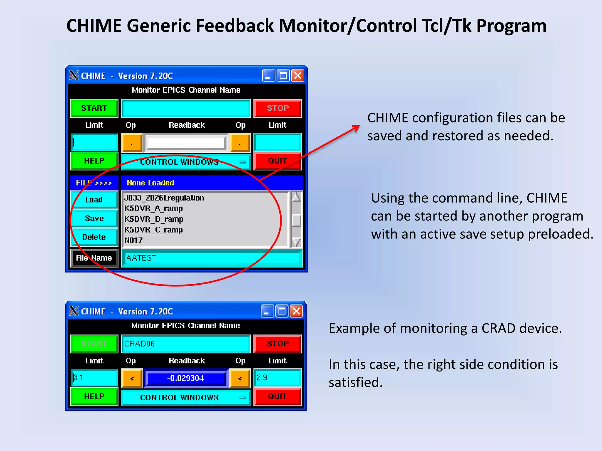
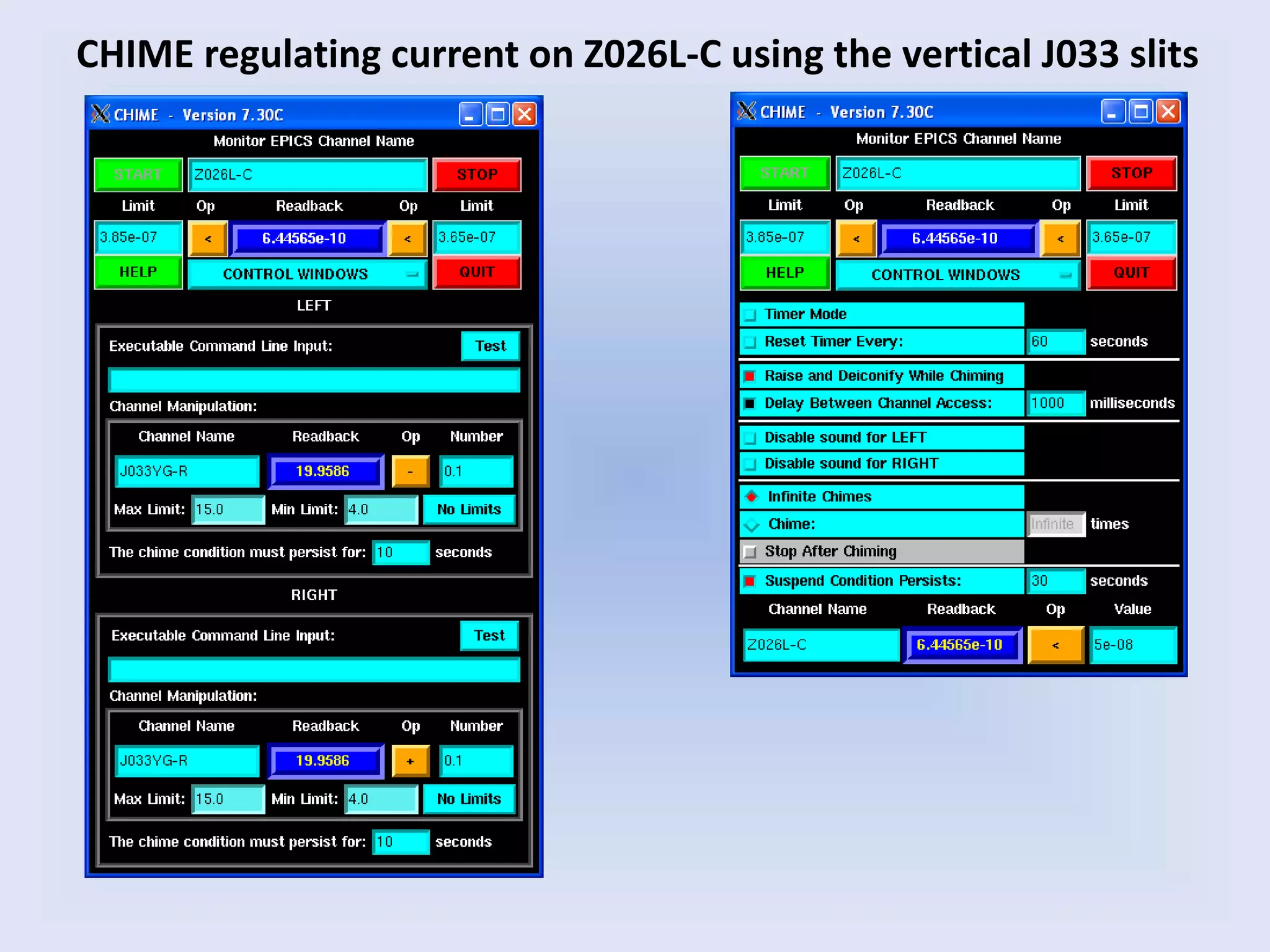
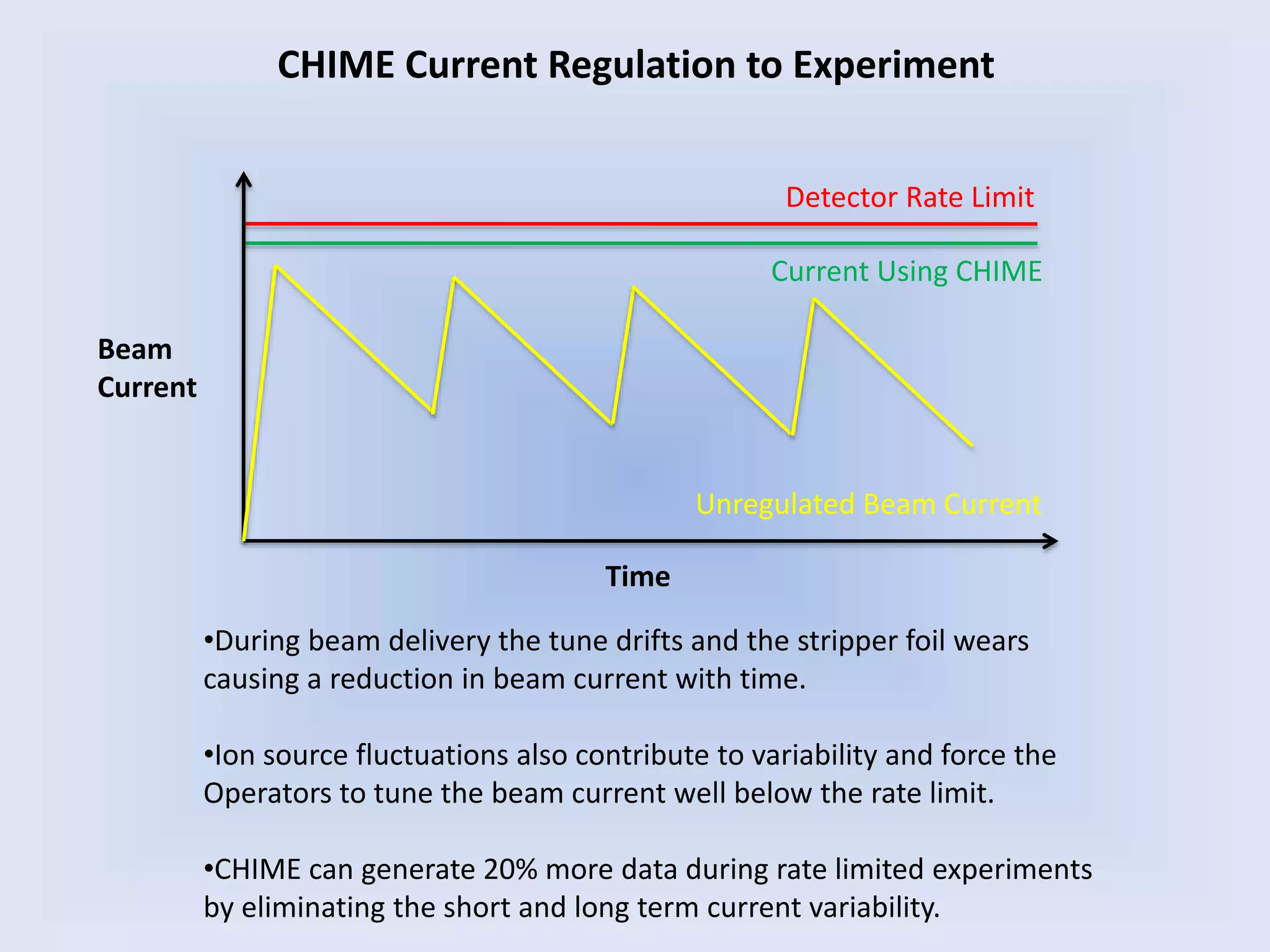
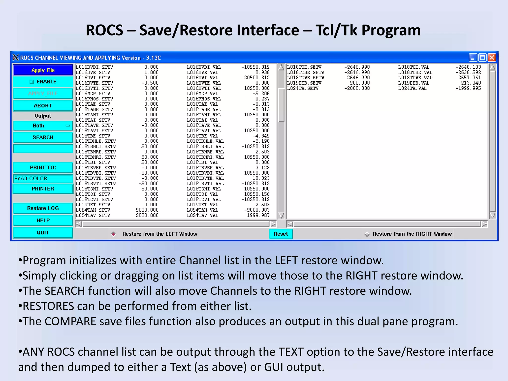
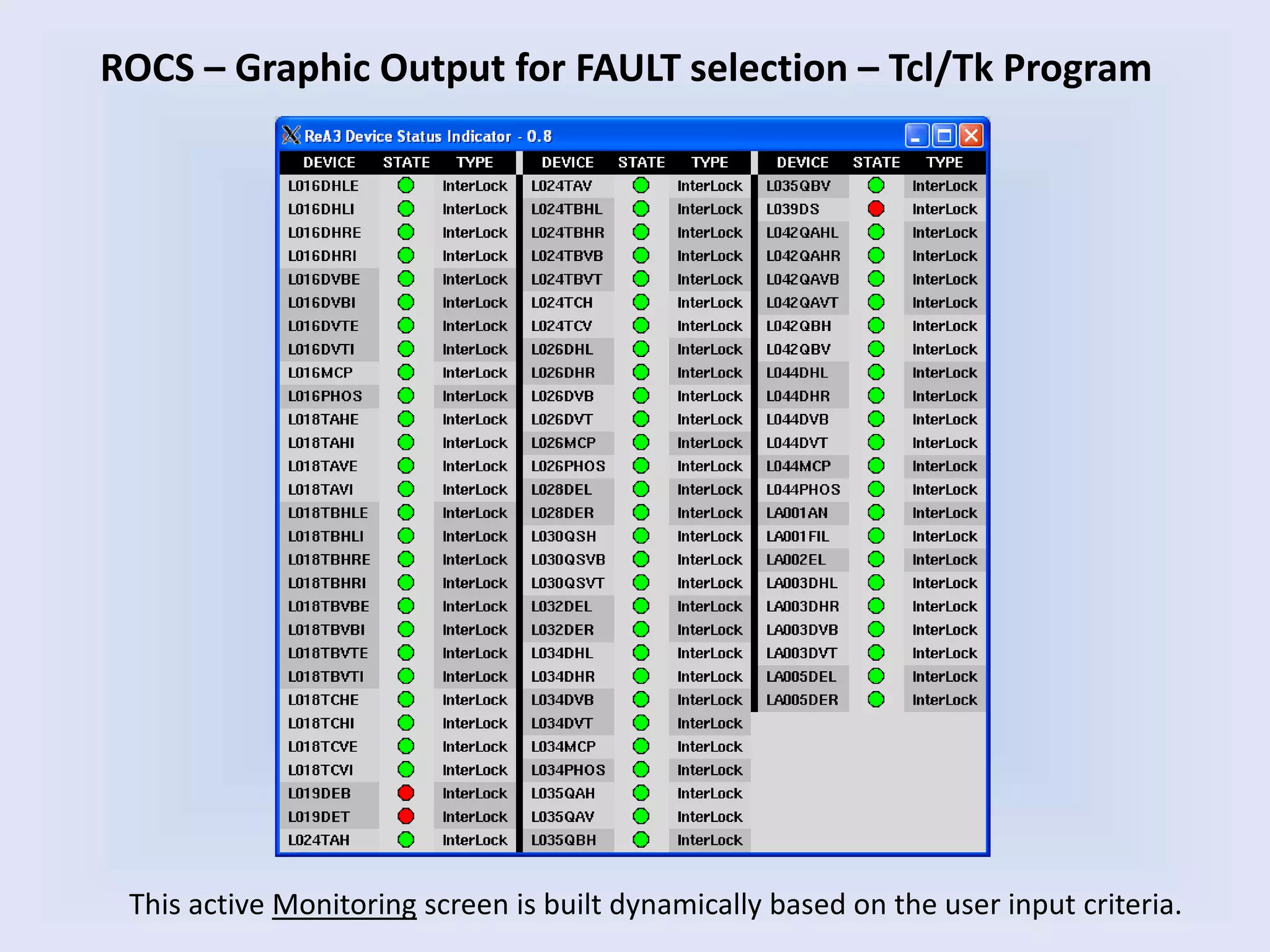
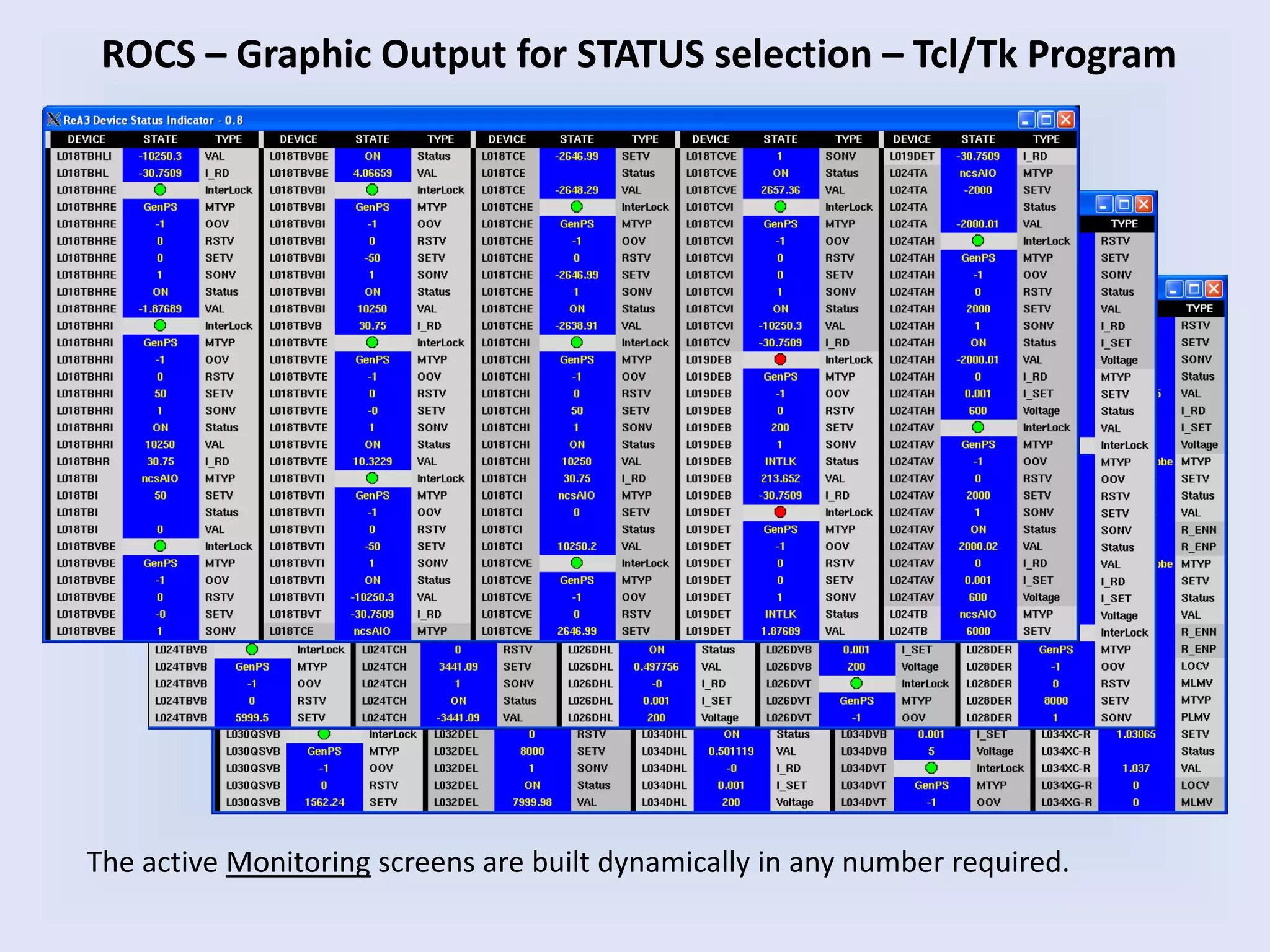
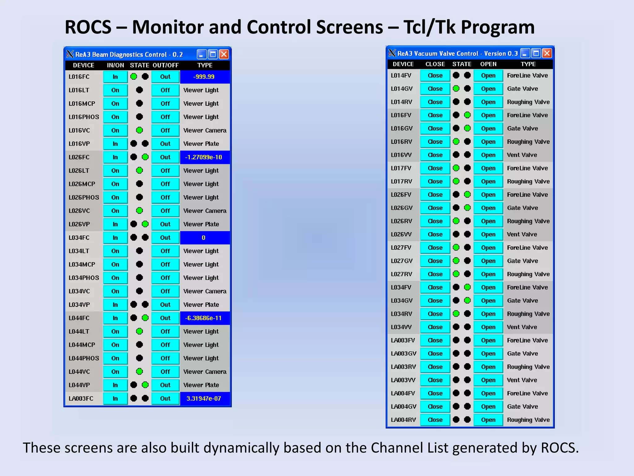
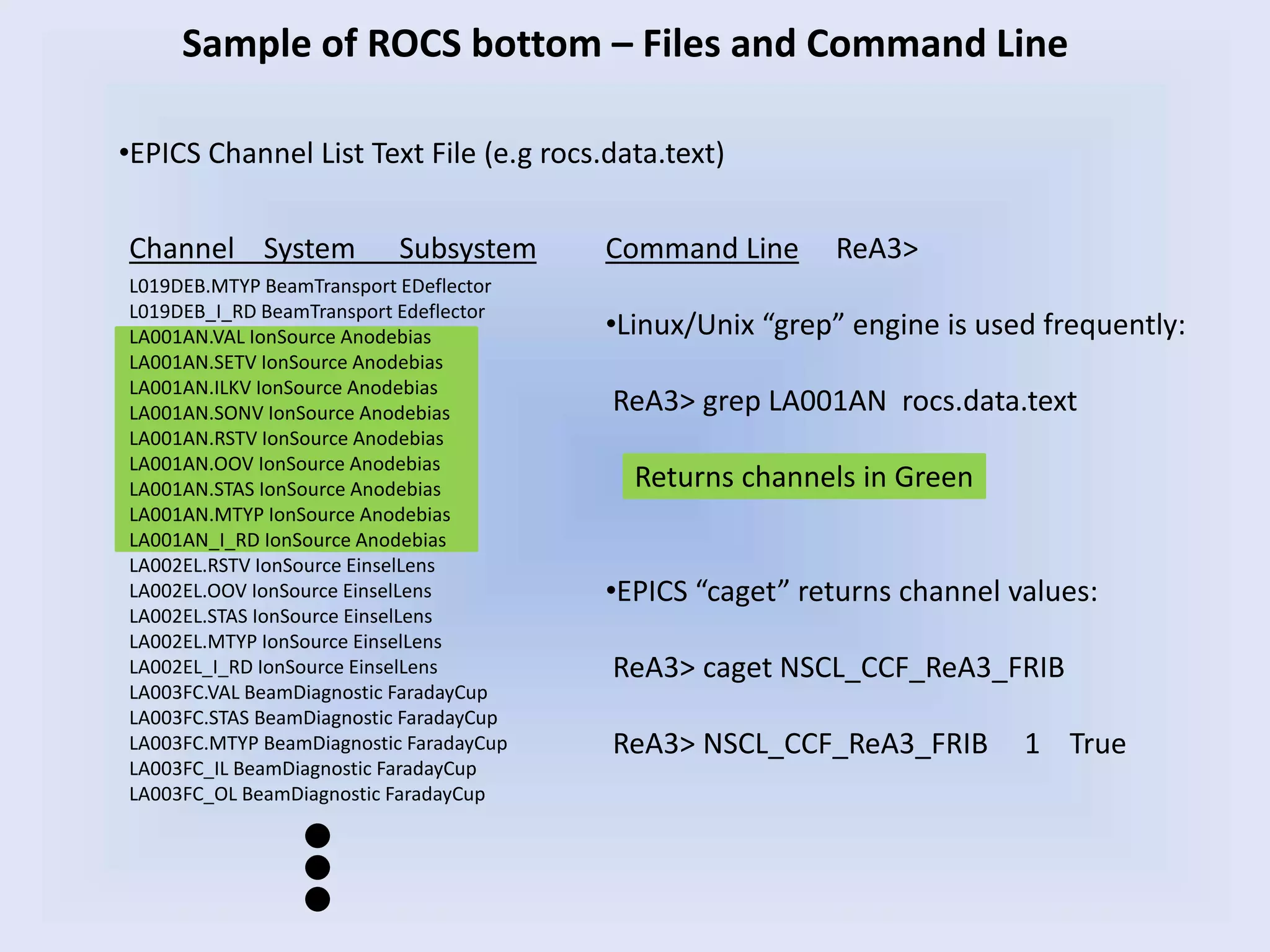
- Examples of high level software applications developed in Tcl/Tk, LabVIEW, and other languages at various facilities to monitor and control systems.