Download as PDF, PPTX

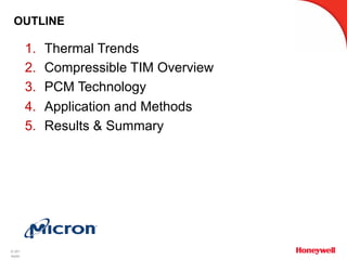
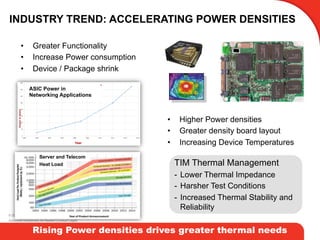
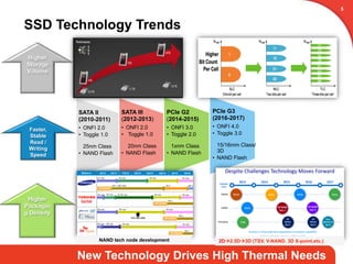
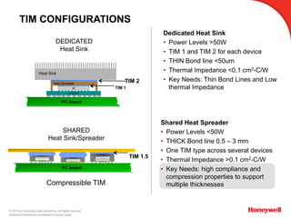
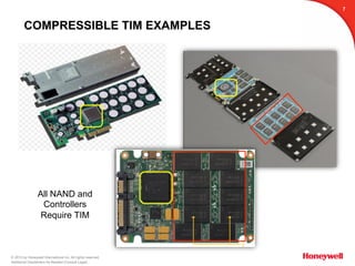
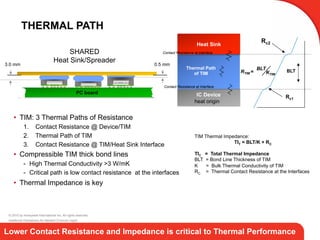
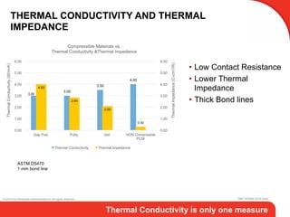
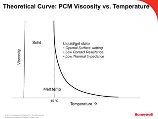
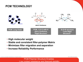
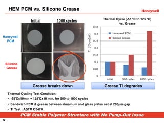
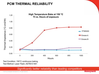
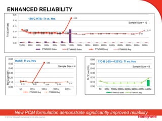
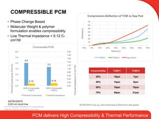
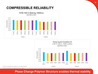
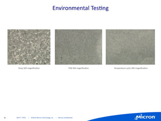
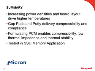

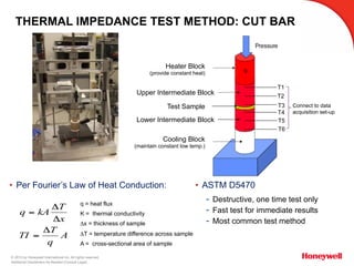
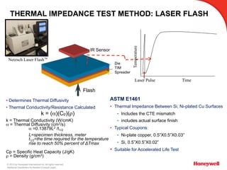

The document discusses the development and application of compressible thermal interface materials (TIM) based on phase change technology for high-performance SSDs, emphasizing the need for improved thermal management due to increasing power densities in electronic devices. It details various TIM configurations and their effectiveness, particularly in terms of thermal impedance and reliability under thermal cycling conditions from extensive testing. The findings highlight the benefits of specific materials like Honeywell's PCM in achieving better compressibility, low thermal impedance, and overall thermal stability for advanced memory applications.


